electronics design
- Assignment
redraw the echo hello-world board,
add (at least) a button and LED (with current-limiting resistor),
check the design rules, and make it

- This is what I made this week, I describe how to make it below.
- Which software to use?
- I used Eagle to design a circuit board and used Dr.Engrave to mill the board (Dr.Engrave is attached to the Modela MDX-20/15).
- We still cannot make
- FabModules working, that is why I used Dr.Engrave.
- In both cases you use Dr.Engrave and FabModules to mill, what you need to do before milling is to draw a monochlome(black and white) board layout image.
- So you can use any software to draw a board but images should be PNG format for FabModules and BMP for Dr.Engrave. Also, the color should be RGB color, it means black parts (where a Modela doesn't mill) should be R0 G0 B0 and white parts (where a Modela mills) should be R255 G255 B255.
- Eagle Tutorial
- This tutorial helped me very much to use Eagle to design a board.
- electronics design tutorial written by FabLab Providence
Your archives help me every week, I love you, Providence!!!
- Just for your information, here I attatched my board design.

^ board layout (You will check 'monochlome' checkbox when saving this file as png, then it will be monochlome.)
^ schematic (I chose 100ohm resistor to limit the current to the LED instead of 499ohm resistor used in the Providence tutorial I showed above.)
- Design the board
- I used Adobe Illustrator to design the board itself, not its circuit.
- 2 weeks ago when we made a FabISP, I saw this picture and thought its handwriting-style pictures were very cute.

- This is made by Sanchez Francisco in FabLab Barcelona.
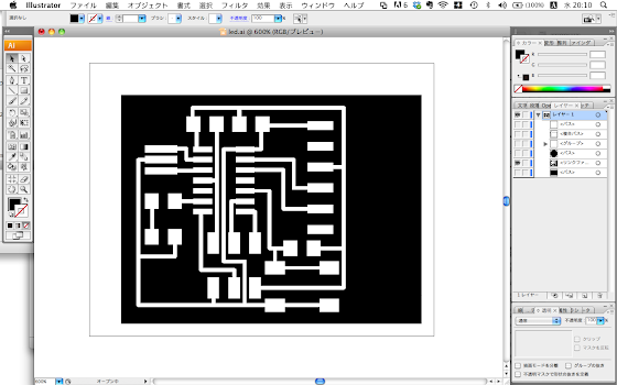
- I used Illustator. Firstly I put the board image made on Eagle on Illustrator.

- Then I drew other parts to it. I used a brush to write the letters 'LED'. (Windows > Brush ([Machintosh] or click F5))

- As I mentioned above, be careful to make this file in RGB color mode. (File > Document Color Mode > RGB color) (*I just translated my Illustrator in Japanese so these names can be wrong.)
Also the black color needs to be R0 B0 G0 and the white color needs to be R255 G255 B255. (Windows > Color ([Machintosh] or click F6) then you can see an inverted triangle at the top-right of the Color window, click it to choose RGB. Then adjust the colors.)
- I saved this as a png file in 500 ppi. When put the png file on Dr.Engrave, the scale will be different, be careful about it.
- pixel to mm caliculator
(It's in Japanese, ピクセル is pixel, センチ is cm and ミリis mm. And you can regard dpi as the same as ppi in this case.)
- How to mill the board?
- If you use Dr.Engrave, see my page on Electronics Production.
- (Sorry this tutorial is still in progress. What you need to be careful is to use 1/64inch diameter or similar diameter endmill to mill the circuit part and to use 1/32 diameter or similar diameter endmill to cut out the circuit board itself from the laminate board.)


