Machine Design
Assignment: The group project is to design a motion control machine.
Using machines
Other machine design assignments.
- Mechanical design simple machine.
- Final Project's Zoetrope.
- Initial project machine design proposal.
- Building a 3D printer kit.
Automata
Automata utilize a wide range of the mechanical processes found in machinery. Designing and making the automata covers a range of skills and processes from art, engineering and maths through to the digital fabrication of the automata.
Design and Construction
- Team: Astrid and myself formed a team of two. We both have developed a strong skill set as students of the Fab Academy and were eager to have fun in developing something together.
- Inspiration: After designing and developing different gearing systems Astrid and I came to an agreement to create an automata.
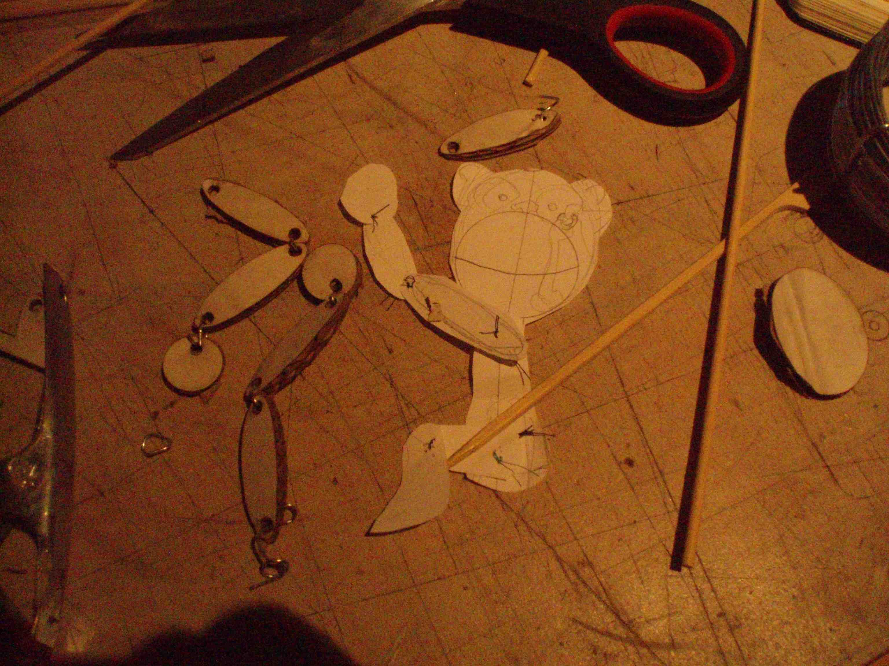
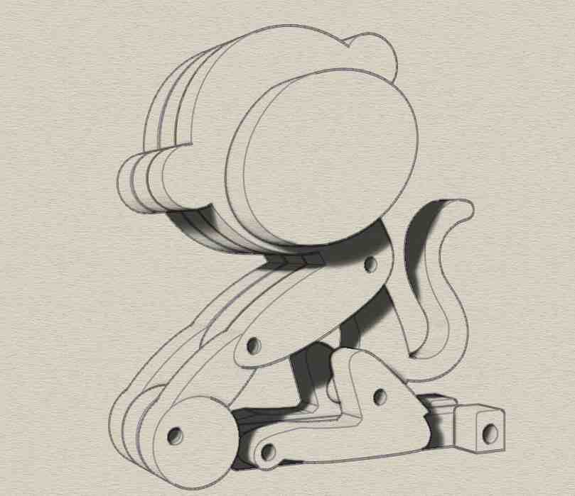
- Design & Development: The initial designs came from brainstorming and making sketches. We wanted the automata to have a fun aspect. The automata needed to be simple, keeping it flat yet 3D. The movement We had to decide how it would move and how the movement would fit in the design.
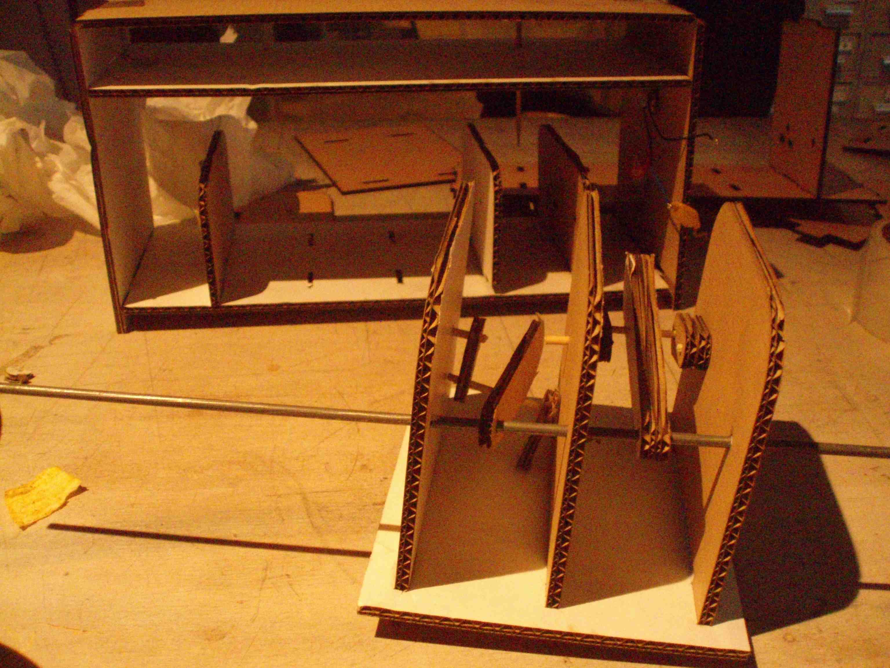
- Working Model & Preliminary Evaluation: From the design sheets, we created a working model out of cardboard. We discovered what did and did not work saving a lot of time and energy by producing a working model.
|
|
|

|
Engineering Principles
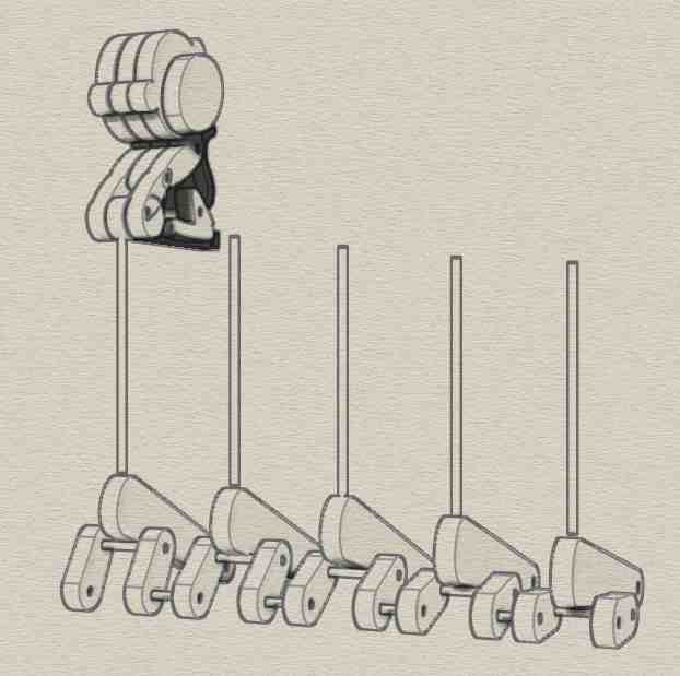
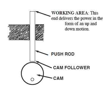
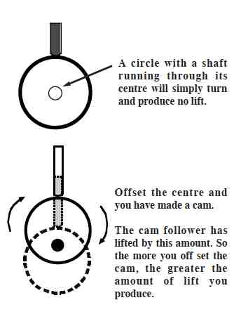
Cam
Astrid and I used cams to make the automata produce a linear movement.
Using multiple concentric cams each slightly offset from the preceding one.
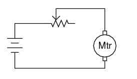
Drives
A battery powered motor is the rotating input for the automata. The advantage of using a motor is that it give a constant output, so the automata is less likely to be damaged or jam.
A potentiometer is used as a rheostat using the wiper terminal and one of the other terminals,
the third terminal left unconnected and unused:
Final Outcome
 Lessons learned
- Assembling the Automata without the precision necessary caused too much friction. Resulting the Automata to have a jerky movement.
- Proposed solution to reduce friction; re-glue cams with more precision, smooth surfaces of cams and push rods.
- The motor jammed and didn't turn the crank on the Automata when assembled with all the monkeys.
- Proposed solution to prevent jamming that Astrid and I tried included larger motor and adding gears
Motors have low torque and high speed. Astrid and I needed high torque and low speed. If you turn the small gear, the big gear goes slower. If you turn the big gear, the small gear goes faster. The slow one has more torque (it can push harder).
Unfortunately this didn't stop the motor jamming. Proposed next step would be to change gear ratio.
More Machine Design
Initial Project Proposal
This initial proposal was rejected due to conflicting team members schedules.
Doorbell to enter Waag Fab Lab rings the telephone which frequently is not heard.
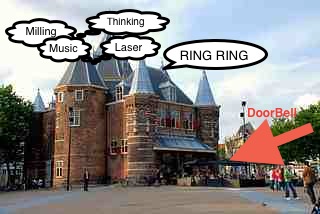
Proposed Solution
When the telephone is ringing create a visual notification.
Bus Network: One wire for on/off communication keying. Whenever telephone line is ringing each node takes a turn controlling the bus for x-number.
Tasks Overview
- Design boards
- Design a motion control visual notification for when node has control of bus.
- Cut and stuff boards
- Cut motion control visual notification.
- Write program for boards.
- Program boards.
- Individual node tests
- Integrate nodes and motion control visual notification
- Hack telephone line.
- Installation
Home mini FabLab
My goal is to build some affordable desk-top digital fabrication machines. Of course these desk-top tools are no match for the MIT standard FabLab machines, however for modest ambitions they can be just what is required.
Starting with a 3D Printer, which I have found very useful in fabricating parts, even though they are disdained by some people.
The printer I chose has the following parts:
- Aluminum frame
- Drylin-sliding bearings
- Opto-sensor
- NEMA 17 motor
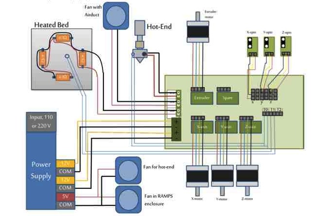
- RAMPS 1.4 electronics
Skills: Basic soldering, mechanical construction, technical insight, and common sense
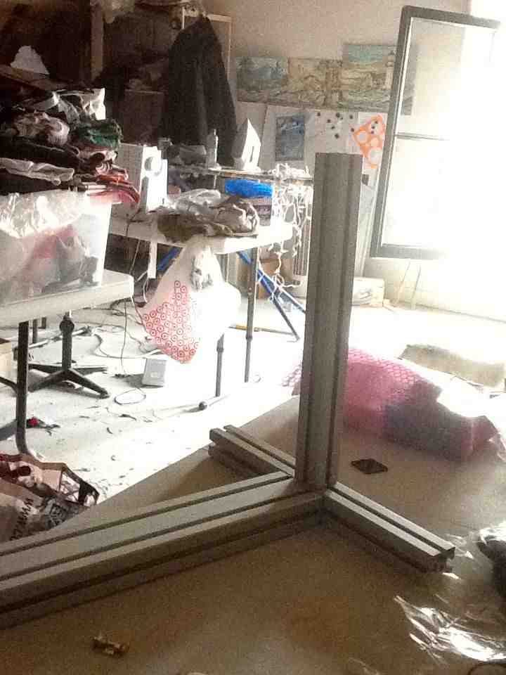
Steps
- Assemble aluminum frame
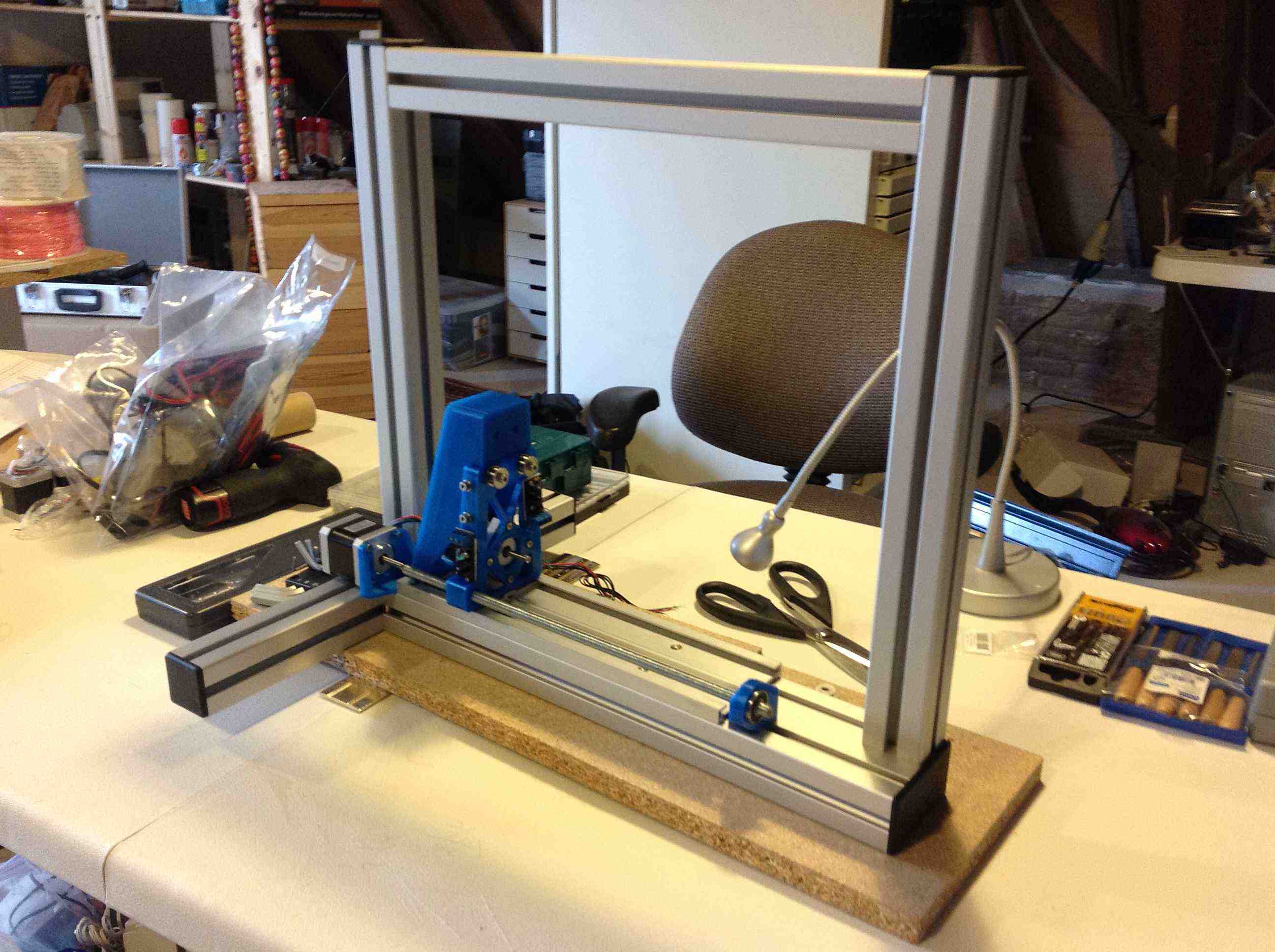
- Assemble x, y, and z axis
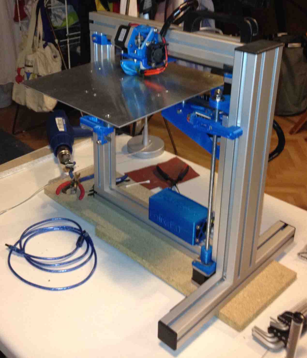
- Assemble extruder
- Solder resistors and thermistor to the heated-bed
- Following schematic connect wires to power supply
Unfortunately the heat-sinks are missing and I am waiting on parts from the manufacture.
Next steps: Place heat sinks on the chip on the stepper drivers, loading software to board, calibration of table in each direction, and fine tune.
Remember: Read through instructions and check that all parts are included.
|
|
|

|

|

|

|
|