|
Assignment 9:embedded programming.
For the electronics design assignment we produced a 'hello world' board without really paying attention to what it 'does'. In this assignment we dived into the data sheet of the ATtiny44 microcontroller and programmed it to do something in as many languages as possible (=1 in my case). Up to now I set my LED on, and I am on my way to make it do some more.
It is amazing how much there is to learn about such a tiny component.....250 pages!!!
The data sheet gives detailed information on how the internal system works, what each pin can be used for, and example code that shows how to use various parts of the device.
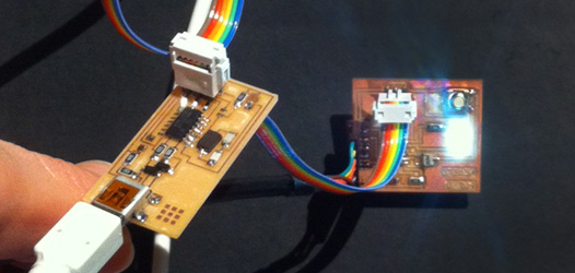
The microcontroller can be programmed with the help of the fab ISP board that was made in class 4. The fab ISP board is needed to program the microcontroller of the hello world board. Connect the fab ISP to the computer with the (white) usb cable, and to the hello world board using the multi colored wire. Connect the hello world board with a (black) ftdi cable in the usb of the computer to create a closed circle. Now download the provided hello.ftdi.44.echo files and save them in a local folder. Also download pyserial and crosspack if you work on a mac. Go to the terminal and open the local folder. Then, one by one, type the commands that are highlighted in this picture:
make -f hello.ftdi.44.echo.c.make
The first command line converts the program called 'hello.ftdi.44.echo' that was written in C (a language that is supposed to be easy to understand for humans) into a hex file that the microcontroller can easily understand.
sudo make -f hello.ftdi.44.echo.c.make program-usbtiny-fuses
The second command can be described as putting 'brains' in the microcontroller. It tells the microcontroller to listen to its own chrystal.
sudo make -f hello.ftdi.44.echo.c.make program-usbtiny
The third command writes this demo programme called 'hello.ftdi.44.echo.c' on the microcontroller.You can now remove the ISP board.
python term.py /dev/tty.usbserial-FTF3GVPD 115200
This last line is for opening the term.py dialogue, that will function as an interface to get output from the microcontroller directly.
On the desktop a dialogue called term.py appears. The program that we just wrote on the microcontroller works like this: when hitting a key on the laptop keyboard the echo hello world board returns the letter that was typed in the term.py dialogue on the computer screen.
When the board is has been disconnected to the computer type the fourth line in the terminal (first go to the correct folder) to make the dialogue pop up again. For some reason this is the only way to get the dialogue appear in your screen.
When you want to make changes to the program on the microcontroller, you can do this using a compiler - I used XCode for OSX. Change or edit the code and save it as a .c file. Then use the first command (but with the name of your program) to convert the C code into a hex file. Then connect the ISP board again and use the third command to write the hex file to the microcontroller. The terminal will let you know if something is wrong with the code.
For beginners it is best to read the code provided by Neil, try to understand how it works and then start changing and adding things. To make a start I read these tutorials on the working of the ATtiny, embedded programming in C, and the basics of C which were very helpful.
My first step was to set the pin of the LED high, which worked. Then I wanted to write a code to include the button. The program did not work yet, because one piece in the initial code had to be switched off. Here is the code I finally uploaded to the board
//
//
// hello.ftdi.44.echo.testdrie.c
//
//
115200 baud FTDI character echo, with flash string
//
// set lfuse to 0x7E for 20 MHz xtal
//
// Neil Gershenfeld
// 12/8/10
//
// (c) Massachusetts Institute of Technology 2010
// Permission granted for experimental and personal use;
// license for commercial sale available from MIT.
//
#include
<avr/io.h>
#include
<util/delay.h>
#include <avr/pgmspace.h>
#define output(directions,pin) (directions |= pin) // set port direction for output
#define set(port,pin) (port |= pin) // set port pin
#define clear(port,pin) (port &= (~pin)) // clear port pin
#define pin_test(pins,pin) (pins & pin) // test for port pin
#define bit_test(byte,bit) (byte & (1 << bit)) // test for bit set
#define bit_delay_time 8.5 // bit delay for 115200 with overhead
#define bit_delay() _delay_us(bit_delay_time) // RS232 bit delay
#define half_bit_delay() _delay_us(bit_delay_time/2) // RS232 half bit delay
#define char_delay() _delay_ms(10) // char delay
#define serial_port PORTA
#define serial_direction DDRA
#define serial_pins PINA
#define serial_pin_in (1 << PA0)
#define serial_pin_out (1 << PA1)
#define max_buffer 25
void get_char(volatile unsigned char *pins, unsigned char pin, char *rxbyte) {
//
// read character into rxbyte on pins pin
// assumes line driver (inverts bits)
//
*rxbyte = 0;
while (pin_test(*pins,pin))
//
// wait for start bit
//
;
//
// delay to middle of first data bit
//
half_bit_delay();
bit_delay();
//
// unrolled loop to read data bits
//
if pin_test(*pins,pin)
*rxbyte |= (1 << 0);
else
*rxbyte |= (0 << 0);
bit_delay();
if pin_test(*pins,pin)
*rxbyte |= (1 << 1);
else
*rxbyte |= (0 << 1);
bit_delay();
if pin_test(*pins,pin)
*rxbyte |= (1 << 2);
else
*rxbyte |= (0 << 2);
bit_delay();
if pin_test(*pins,pin)
*rxbyte |= (1 << 3);
else
*rxbyte |= (0 << 3);
bit_delay();
if pin_test(*pins,pin)
*rxbyte |= (1 << 4);
else
*rxbyte |= (0 << 4);
bit_delay();
if pin_test(*pins,pin)
*rxbyte |= (1 << 5);
else
*rxbyte |= (0 << 5);
bit_delay();
if pin_test(*pins,pin)
*rxbyte |= (1 << 6);
else
*rxbyte |= (0 << 6);
bit_delay();
if pin_test(*pins,pin)
*rxbyte |= (1 << 7);
else
*rxbyte |= (0 << 7);
//
// wait for stop bit
//
bit_delay();
half_bit_delay();
}
void put_char(volatile unsigned char *port, unsigned char pin, char txchar) {
//
// send character in txchar on port pin
// assumes line driver (inverts bits)
//
// start bit
//
clear(*port,pin);
bit_delay();
//
// unrolled loop to write data bits
//
if bit_test(txchar,0)
set(*port,pin);
else
clear(*port,pin);
bit_delay();
if bit_test(txchar,1)
set(*port,pin);
else
clear(*port,pin);
bit_delay();
if bit_test(txchar,2)
set(*port,pin);
else
clear(*port,pin);
bit_delay();
if bit_test(txchar,3)
set(*port,pin);
else
clear(*port,pin);
bit_delay();
if bit_test(txchar,4)
set(*port,pin);
else
clear(*port,pin);
bit_delay();
if bit_test(txchar,5)
set(*port,pin);
else
clear(*port,pin);
bit_delay();
if bit_test(txchar,6)
set(*port,pin);
else
clear(*port,pin);
bit_delay();
if bit_test(txchar,7)
set(*port,pin);
else
clear(*port,pin);
bit_delay();
//
// stop bit
//
set(*port,pin);
bit_delay();
//
// char delay
//
bit_delay();
}
void put_flash_string(volatile unsigned char *port, unsigned char pin, PGM_P str) {
//
//
print a null-terminated string from flash
//
static char chr;
static int index;
index = 0;
do {
chr = pgm_read_byte(&(str[index]));
put_char(port, pin, chr);
++index;
} while (chr != 0);
}
void put_ram_string(volatile unsigned char *port, unsigned char pin, char *str) {
//
//
print a null-terminated string from SRAM
//
static int index;
index = 0;
do {
put_char(port, pin, str[index]);
++index;
} while (str[index] != 0);
}
int main(void) {
//
// main
//
static char chr;
static char buffer[max_buffer] = {0};
static int index;
//
// set clock divider to /1
//
CLKPR = (1 << CLKPCE);
CLKPR = (0 << CLKPS3) | (0 << CLKPS2) | (0 << CLKPS1) | (0 << CLKPS0);
//
// initialize output pins
//
set(serial_port, serial_pin_out);
output(serial_direction, serial_pin_out);
DDRA |= (1 << PA7); //pin a7 is the output pin for the LED
DDRB &= ~(1 << PB2); //pin b2 will be the input (= not output) pin for the button
PORTB |= (1 << PB2); //use pull-up on pin b2
//
// main loop
//
index = 0;
while (1) {
if ((PINB & (1 << PB2)) == (1 << PB2)) { //we want to know if pinb2 equals zero, because that means the button is pressed and the power goes to the ground. The statement is only true if pinB2 is not zero.
PORTA &= ~(1 << PA7); // if statement is true then switch the LEDs off
}
else
{
PORTA |= (1 << PA7); // and else switch the LED on.
}
/*
get_char(&serial_pins, serial_pin_in, &chr);
static char message[] PROGMEM = "Hallo Astrid: you typed \"";
put_flash_string(&serial_port, serial_pin_out, (PGM_P) message);
buffer[index++] = chr;
if (index == (max_buffer-1))
index = 0;
put_ram_string(&serial_port, serial_pin_out, buffer);
put_char(&serial_port, serial_pin_out, '\"');
put_char(&serial_port, serial_pin_out, 10); // new line
*/
}
}
|
 Astrids Fab Academy Projects