|
Assignment 16: Machine design
This weeks group assignment ws to make a machine, and make it do something. Cynthia and me worked together on a project. Together with Alex we decided to make 'something that translates a rotation into a linear movement'.
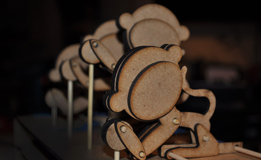
We decided to make an automata that makes four monkeys do a wave.
How it works
Cynthia made a good explanation of the engineering principles!
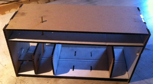
The system consists of rods, that are driven by the motor. The box is separated in four parts with each two cams that are connected via a bar. Each cam is also connected to the cam in the next segment of the box via a bar that goes through the wall that separates the segments. As the cams rotate they will push the sticks in each segment up and down through the top of the box. The monkeys are attached to the sticks, so they will do their wave.
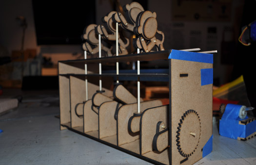
There is an offset between the cams in the different parts, so in the end the monkeys will each have a different position.
Paper prototyping the cams
First we watched lots of videos to find out how to translate the motion. Then we made some prototypes out of cardboard to determine the size and lengths of the cams, the distance between the parts, and the lengths of the sticks and the amplitude of the monkeys.
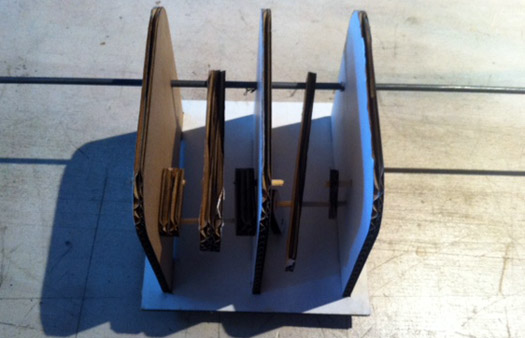 Each segment contains two small cams that make a long bar go up and down Each segment contains two small cams that make a long bar go up and down
Each segment guides one stick through the lid of the box. The stick will be supported by the long bar (see image above).
Designing the parts
When we had the desired construction in cardboard we finalized the drawings in illustrator and cut the parts with the lasercutter. We worked with 3 mm mdf. Sometimes the connections are snug in the beginning but when you put the thing together many times the pressfit becomes loose again.
Putting the cams and rods together
We had to glue the system together piece by piece, which took a lot of time. We practiced a couple of times before glueing everything, because once everything is joined it can not be taken apart anymore.
The long bars were going up and down smoothly, but we discovered the alignment was very important - otherwise the sticks can fall off the bar. To prevent the sticks from falling we attached little circles at the bottom, so they look like skiing sticks. This worked well. We were wondering whether a bit of vaseline would help to guide the sticks over the moving bar.
Putting the monkeys together
The monkeys consist of legs, body, arms+head, hands and a bar that attaches them to the top of the box. Their feet and heels are all connected via long rods. The 'joints' of the monkeys are sateh sticks. In the beginning they were a bit stiff but after some training they were moving smoothly.
Driving the system
A dc motor drives the automata. The motor is attached to the first rod on one side, and since all the parts are connected it will make all the cams rotate.
We found out that quite some force is needed to rotate the rods. Therefore we designed a set of gears to drive the system. the motor is attached to the small gear and the large gear is attached to the rod. When we attached the motor we got the cams moving a bit, but a heavier motor would be needed to get it running smoothly.
Test with the motor driving the gears
Lessons learned
- It was really nice to work together! It was great to learn from the others' perspective, we learned a lot by solving all our little issues together and encouraged each other to continue. We divided the drawing and glueing tasks, and when putting everything together we often needed 4 hands!
- Precision and alignment is crucial. Each flaw can cause the system to get stuck. Wooden sticks were not the best solution for the rods.
- In the end the motor was driving the gears, but attached to the automata it did not get the monkeys moving smoothly. The automata worked nicely when operated manually, but when we attached the two systems together it jammed. A solution would be to put bearings in the system. This would require a redesign, which would be great to do. But for now we learned what we were aiming to learn!
Our initial idea: a group project
At first we decided to make a doorbel system with the group that makes something move on the wall when the doorbel rings. Every one of us would make a part of the whole system. We wanted to finish it after the final project deadline but due to holidays there was no time to get together anymore... So this is how far we got.
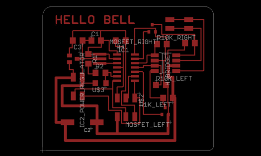
Designing the board
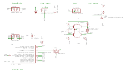
The system is a combination of the light sensor, the DC motor and a network with three nodes. We took the
examples of the light sensor and DC motor board and designed a new board. It was good to practice with Eagle and recall what we learned in assignment 7.
First of all the right parts had to be imported in the schematic with the 'add' function. We took all the components from the hello light board, but left out the attiny, J1 ISP and the FTDI cable. From the hello h-bridge board we took all the components, but left out the J1ISP, and J3. We ad
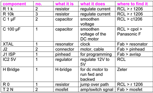
Here is a list of the components and where they can be found in the libraries:
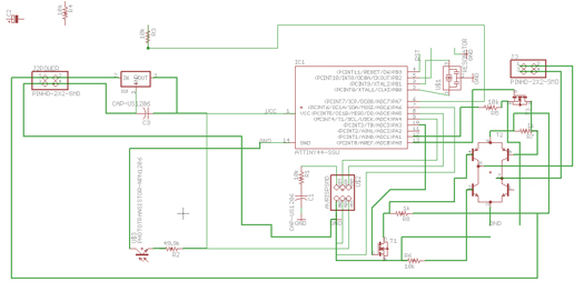
Then all the parts had to be placed and connected in the schematic. At first my schedule looked like this:
A better workflow is to keep the different 'modules' separated and keep them visually apart. To connect them electricall, draw a line with an open end. Then give it a clear tag with the 'name' button. Then click the 'abc' button and select the line. Now the tag appears on top of the line. Everytime you give this tag to another line, Eagle understands that these are connected. This way you keep the overview. With the eye button selected you can click a line in the schematic, and the connected parts will highlight. It is good practice to check each connection in the schedule.
I re-did the schematic and then it looked like this:
When the schematic was done the parts had to be organized on the board. The easiest way was to follow the example DC motor board layout as much as possible and then organize the other components afterwards. With the components more or less in place you can start doing the paths. Select the wire button, click a pad and draw a line to the next pad. The yellow air wires show you where to go. A trick for organizing the parts: click 'ratsnest' every now and then. It tells you the shortest connection between the other components. Thickness of the wires should be +/- 0.016, and the wires from the moter to VCC and GND somewhat thicker. Use the layer tool to adjust the visibility of the name, origin and value layers, if that makes it easier to drag around the parts.
If the board is becoming a big labyrinth and you can not connect parts without crossing a line, you can create a bridge with a 0 ohm resistor. If you like you can place a tekst on the board with the tekst tool. In the 'info' dialogue you can change the ratio to make the tekst bigger.
Then draw the outlines of the board in the dimension layer with the normal line tool, thickness of the outlines should be 0. Delete the square that is already in the field.
Finally do a Design Rule Check. Open the drc dialogue to adjust the settings for your board and milling bit. The clearance should be 16 mil, which is the size of the tracing bit. Set copper/dimension to 1 and run the check. It will show a lits of all the parts that can not be milled correctly. Solve the issues by moving components, wires, and if that doesn't help make the wire slightly thinner so the milling bit can pass. In the end the hello_bell board layout looked like this:
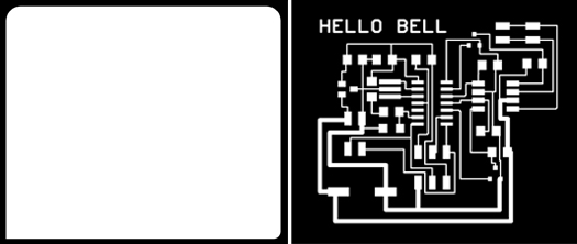
After exporting it with only the top and dimension layer to a 1000 dpi .png image, the board had to be imported in Photoshop to make the outline and trace files. For the outlines, fill everything within the outlines white. For the traces file, remove the white outlines. Save both as .png files.
 Step 1 done, up to milling and stuffing the board. Step 1 done, up to milling and stuffing the board.
Milling and stuffing the board.
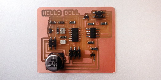
After stuffing the board I checked it for shorts, using the beep function of the multimeter. Everything seems to work fine.
Setting the fuses
For setting the fuses I used the hello.ftdi.44.echo makefile as a starting point, since this code also uses the attiny 44A. I renamed the file hello.bell.make and in the code I changed the name after PROJECT= into the name of my project; hello.bell
Then I ran these commands in the terminal:
make -f hello.bell.make
sudo make -f hello.bell.make program-usbtiny-fuses
The idea is that the fuses are set correctly after running the last command. When running the second command the battery needs to be attached. When I tried the terminal returned the error rc=-1 check connections. When I used a brand new battery the board started smoking.....
Coding
Then the code had to be manipulated. The most important thing is that the board understands it is a node in the network, so the bus code was taken and edited.
In the end the code should be able to:
- get a signal from the master when the bell is ringing
- make the dc motor spin
- measure the amount of revolutions with the light sensor and optical slots in the gears.
- stop the motor after three revolutions.
Flashing the code
sudo make -f hello.bell.make program-usbtiny
Running the motor
Making something that moves
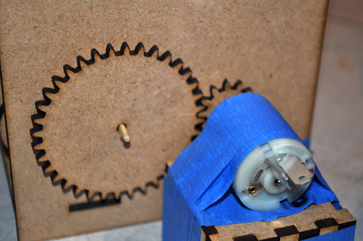
Mounting the gears from assignment 14 on the motor axis. The first gear drives the second gear when the bell rings, and stops running after three revolutions!!
|
 Astrids Fab Academy Projects