Computer Control Machining
For this week's assignment my classmate Branden and I decided to start creating the base exterior design of our larger team project that is part of the weekly assignment in a few weeks. We are creating a 'Smart Bar' where you can mix and match refridgurated drinks. As a team we already researched the necessary parts required for our interior so we have a basic understanding of the necessary dimensions of the actual “smart bar” enclosure. So, we are designing and building the shell of our bar that is big enough to fit a small fridge and all the plumbing interior.
This week assignment content:
Group Assignment:
lab safety training-
test runout, alignment, speeds, feeds, materials, and toolpaths for your machine
Individual Assignment:
make (design+mill+assemble) something big (~meter-scale)
Project files for this week's assignment{ }
"Smart Bar"
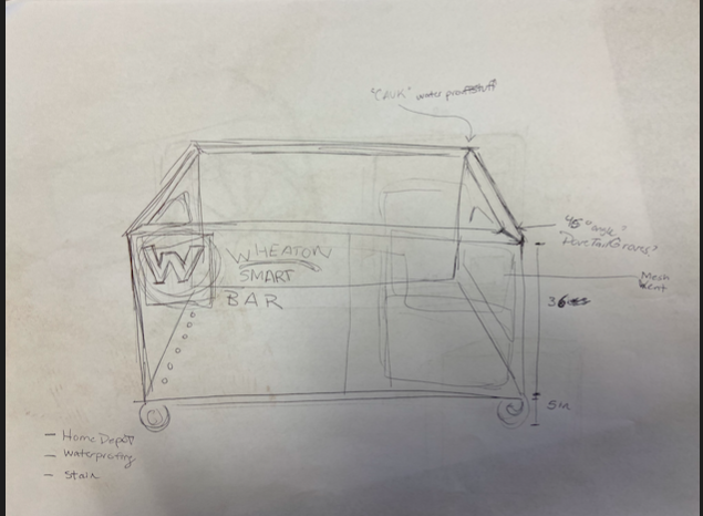
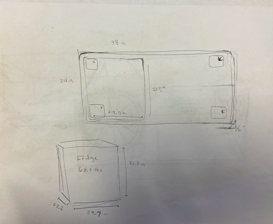
First, Bradon and I hand drew our idea on paper and wrote out all the height and weight legistics that needed to be accounted for. Like the dimentions of our Fridge and the extra space needed fore plumming.
Group Assingment
But before we started designing in fusion and transforming it into a cut design using the CNC, my group had to create a test cut using VCarve.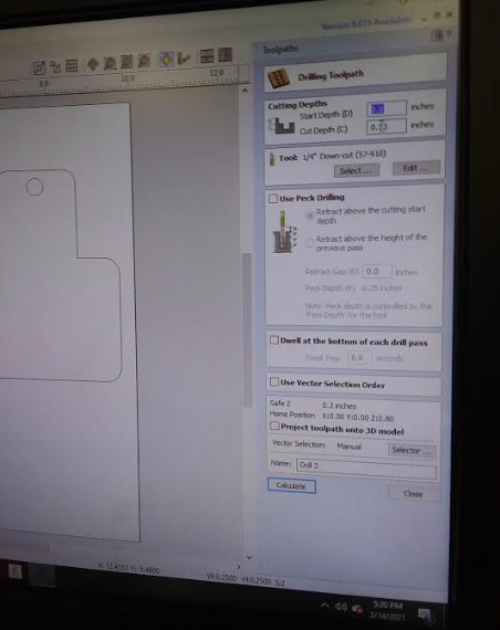
The small edge of the right-hand piece needed to be able to fit into the slot inside of the left-hand piece. However, the CNC has difficulty making 90 degree interier angles, so we needed to make a dogbone cut, which is essentially using the fillet tool on each of the angles. This allows for there to be a sufficient amount of space for the wood piece to fit.
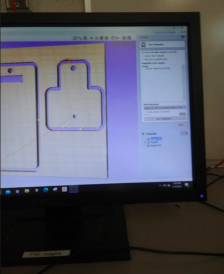
Then we selected the bit and correct tool settings, then exported it to a USB.
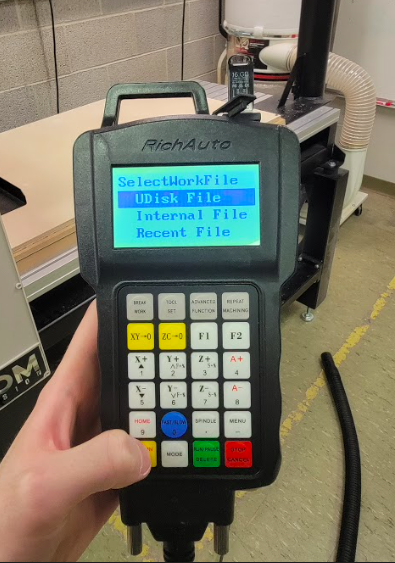
We secured a piece of wood to the bed using screws and double-sided tape. Then we set the X,Y, and Z axis.
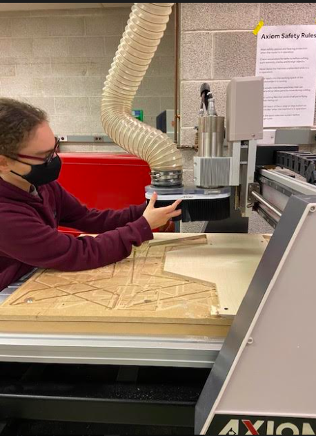
adjusting the dust collector
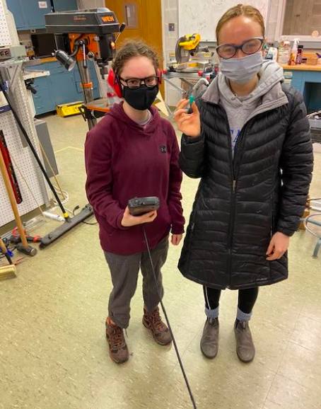
Here we are with our proper protection!
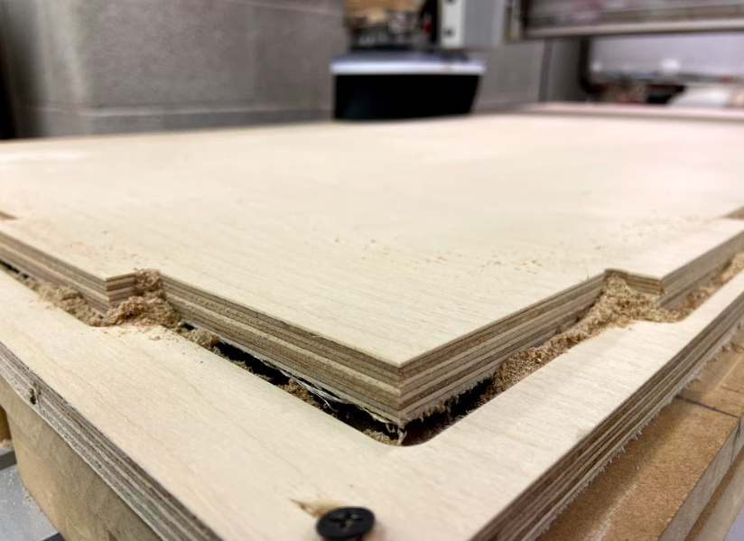
our wood was slightly warped so the peices popped out after they cut through, next time we will make sure to keep the wood kept on a flatter surface for storage.
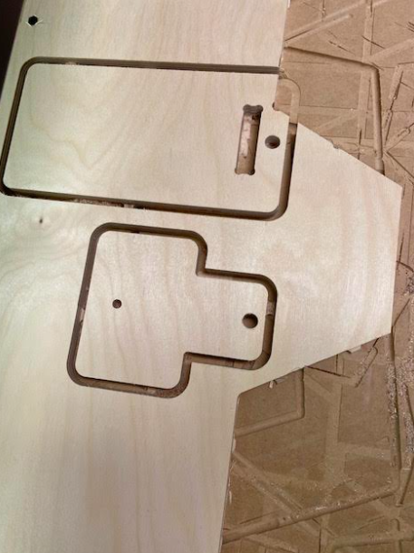
Pieces cut! For the measurements of our cuts, we found- Interior piece: 2.04in Exterior: 2.05in Drill hole: 0.376in
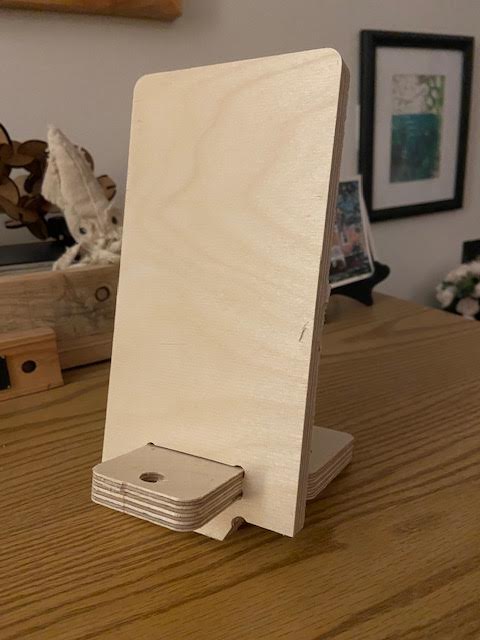
Here is the final product put together, its a phone stand with a place to add in a charger!
Making something Big!
Brandon transformed our design in fusion 360, Here are the finished photos And design files.
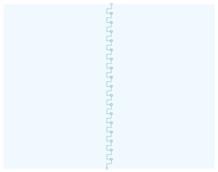
For the front panels of our desgin, we made a rectangle that was the width of 2 pieces of plywood put next to each other. We accounted for a 1/2" cut margin around the entire board meaning that the boards could be up to 23" wide when fully cut. Then, we made made a sketch on the surface of this body of a rectangular pattern down the center to simulate the fingers and grooves that make up a box joint. We used the technique in the following video to make finger joints that account for the clearance needed between fingers. We decided to use a clearance of 0.01" (1/64"), but the design is parametric, so this can easily be changed!

Then we did the same on the sides, except with more shallow grooves and fingers to make the side panels flush with the front.
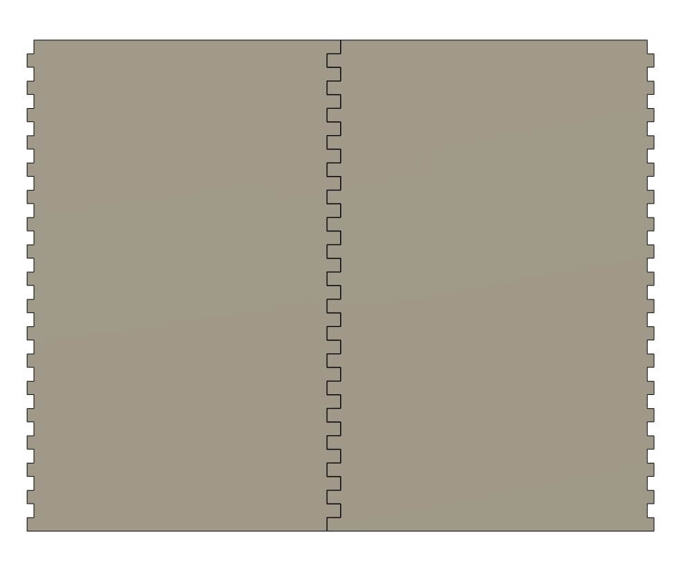
Once we cut out this pattern, our design looked like this. This is the front of our bar.
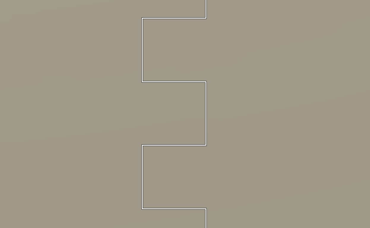
Here is a closeup of our 0.01" clearance gap between the grooves and fingers. This clearance can easily be changed by changing the variable assigned to it. In fact, this whole design was built parametrically!

We wanted a Wheaton Logo on the front panel that we could put colored acrylic and an LED behind. This was created by importing an SVG of our logo.

We new that the fridge we are going to use vents on it's right side, so we incorporated this in the corresponding side panel.
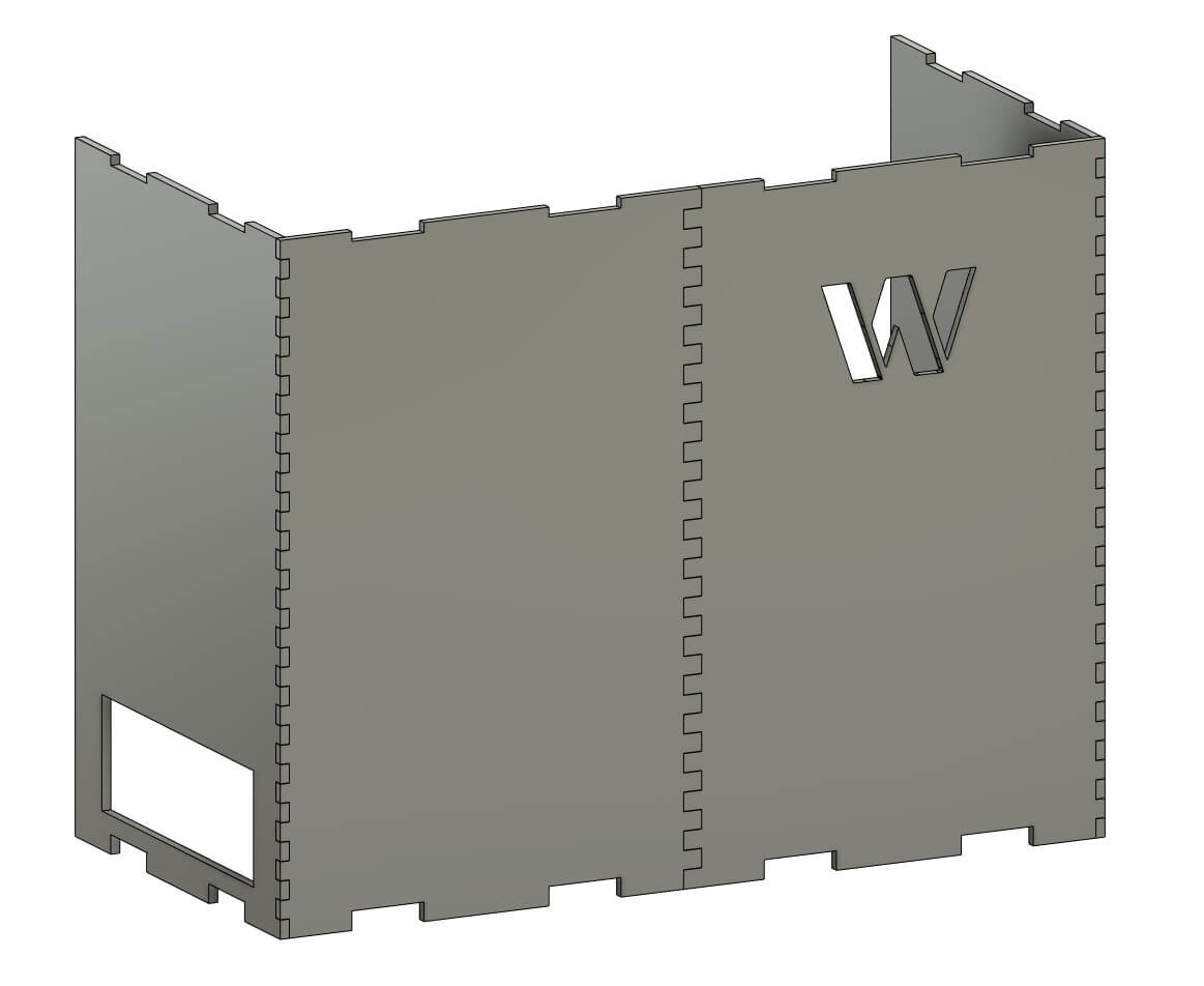
The side panels were designed by following the same rectangular pattern technique, except only on one side. We put everything together and this was the result.
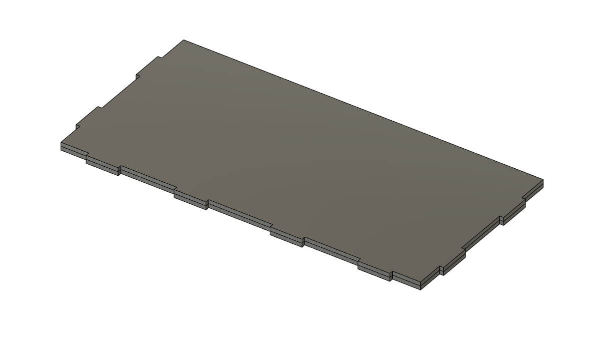
The grooves along the top and bottom were created using this design as the base and countertop. We wanted them to be 2 boards thick for strength.
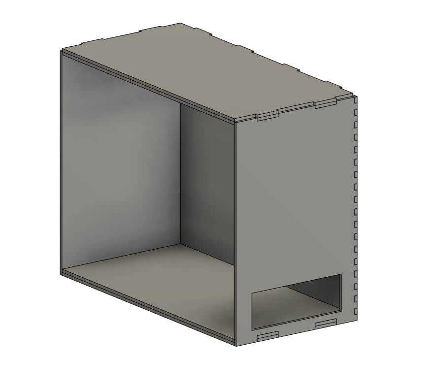
almost done!

The design felt too empty at this point. We decided to model a sign to wrap around the top. This sign also functions as a barrier from any liquids or cups from falling off the top. Plus, it looks really nice! The text was created using the text and push/pull tools in Fusion 360. The text is 0.25" deep: half of our material thickness.
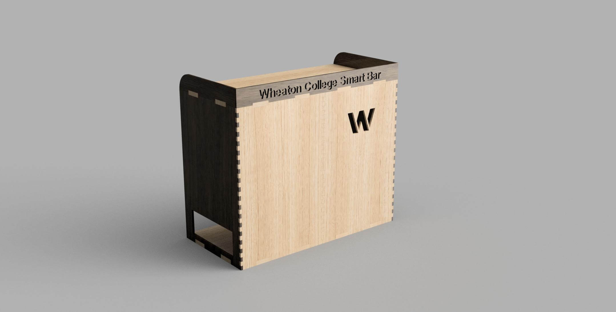
Then, we applied materials to simualte the wood stain we want to apply to our bar. We used Fusion's built-in redering to genarate these images.
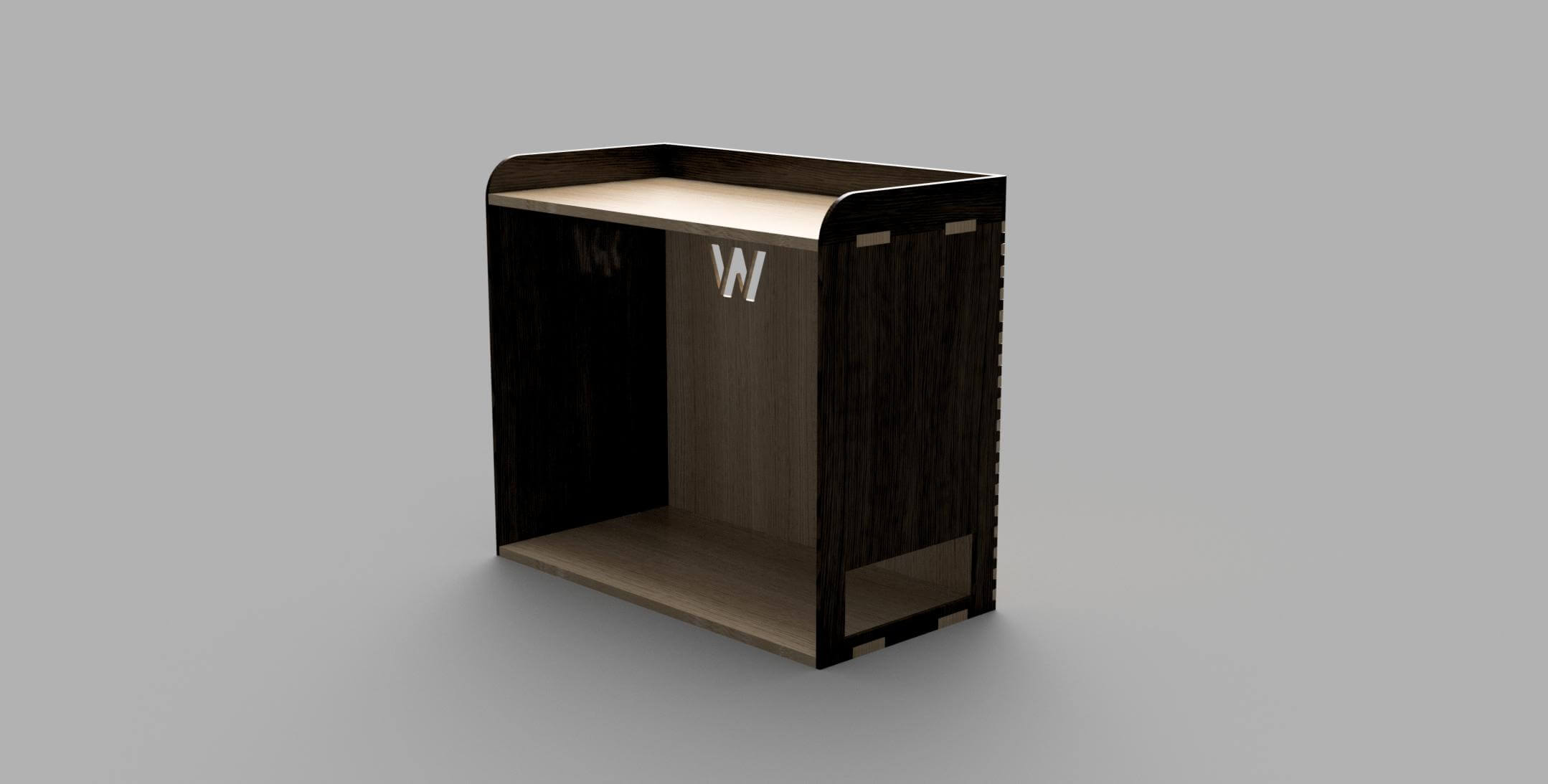
back-view.
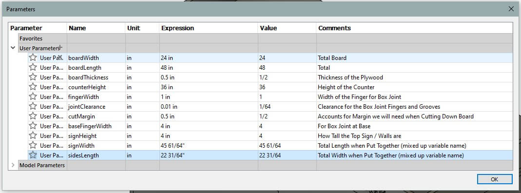
Here are the parameters that we used to design the bar.
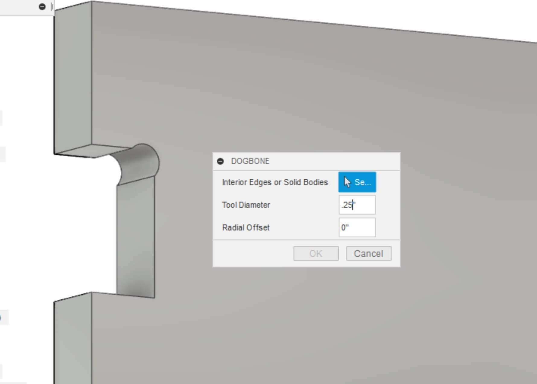
Then we had to dogbone each inner, right angle that allowed our panels to connect with 90° corners. We installed the dogbone addin by tapnair on github that easily and automatically allows you to create dogbones on every selected corner. It bases the diameter of the dogbone based on the user's entered endmill diameter. For us, this was 0.25".
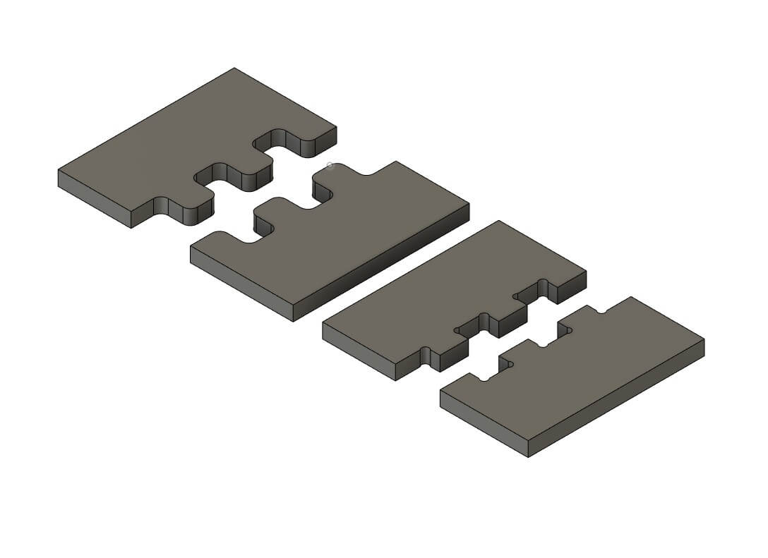
We were nervous as to how these new joints would fit together. We were especially worried about the dogbones and how much light would shine through them. So, we decided to make a small test of each joint to CNC. This is also how we learned to CNC using Fusion 360! It's actually pretty easy once you go through the initial setup!
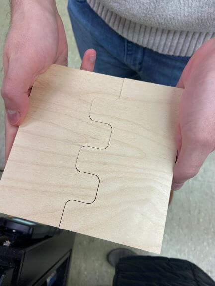
Front joint looked great!
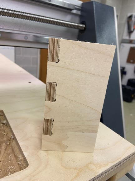
And the corner joints looked amazing! Time for the real thing!
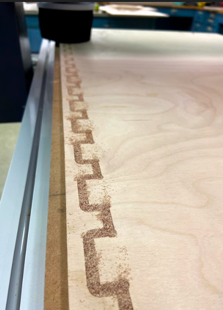
Then we where ready to cut our actual final desgin!

a few issues with our wood panells, they where slitly warped so screwing them to the cnc platfrom was pretty tricky at first.
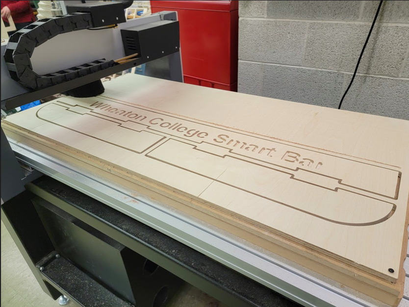
But overall we did not have any issues with cutting out the design, look how cool it is!
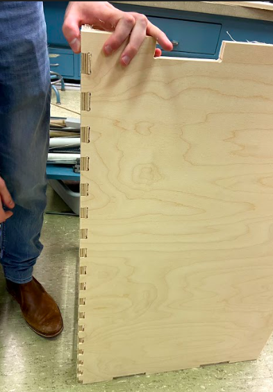
assemboling the dogbone corner joints together to make the side of our bar
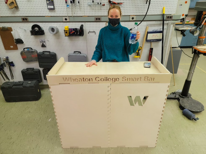
Bar Complete! anyone want a drink?
Here is the link to my project fileslink here!