Week 08. Embedded Programming
Compare the performance and development workflows for different microcontroller families. ✔
Read the datasheet for the microcontroller you are programming. ✔
Program the board you have made to do something, with as many different programming languages and programming environments as possible. ✔
Documented what you learned from reading a microcontroller datasheet. ✔
Programmed your board. ✔
Described the programming process/es you used. ✔
Included your source code. ✔
Included a short ‘hero video’ of your board. ✔
This week assignment content:
Group Assignment:
lThe Group Assignment For the group assignment we recorded the specs for each of the listed boards.
Data Sheet for BorFeather M0
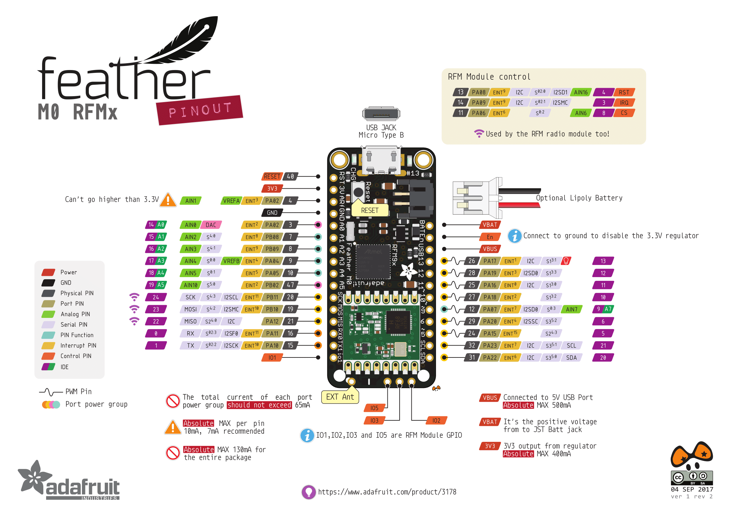
Board: BorFeather M0 lora 900MHz
Processor Family: ATSAMD21G18 ARM Cortex M0 processor,
Bus Width (bits): 20 bytes
Clock Speed: 256K of FLASH
Memory: clocked at 48 MHz and at 3.3V logic
Number of I/O pins: 8 x PWM pins
Logic level voltage: 3.7V Lithium polymer batteries and built in battery charging. You don't need a battery, it will run just fine straight from the micro USB connector. But, if you do have a battery, you can take it on the go, then plug in the USB to recharge.
Pinout diagram: link
Datasheet: link
Data Sheet for RedBoard
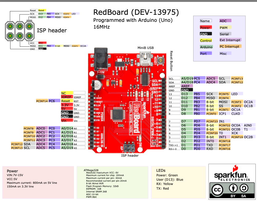
Board:RedBoard
Processor Family:#ATmega328P
Bus Width (bits): 8 bit
Clock Speed: 16MHz Clock Speed
Memory: 32k Flash Memory
Number of I/O pins: 14 Digital
Logic level voltage; 5 volts
Pinout diagram link: link
Datasheet: link
Manufacturer:link
ADA Fruit Mini Microcontroller
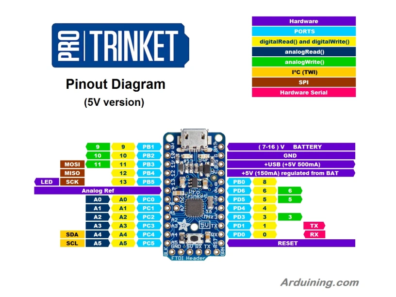
Board:ADA Fruit Mini Microcontroller
Processor Family:#ATtiny85 (AVR)
Bus Width (bits): 5.25K bytes
Clock Speed: 16 MHz
Memory: 8K
Number of I/O pins: 3
Logic level voltage; 5 volts
Pinout diagram: link
Datasheet:link
Manufacturer: link
ATTiny1616
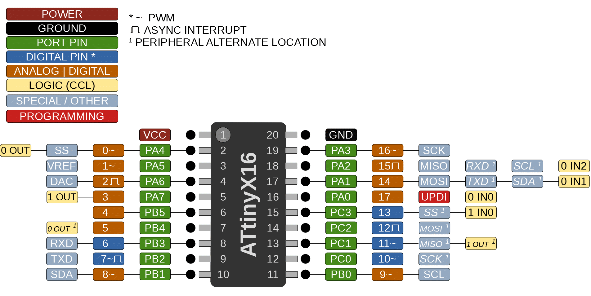
Board:ATTiny1616
Program Memory Type: Flash
Program Memory Size (KB): 16
CPU Speed (MIPS/DMIPS):20
SRAM (B): 2,048
Data EEPROM/HEF (bytes): 256
Digital Communication Peripherals: 1-UART, 1-SPI, 1-I2C
Capture/Compare/PWM Peripherals: 2 Input Capture, 6PWM
Timers: 1 x 8-bit, 3 x 16-bit
ADC Input: 16 ch, 10-bit
Number of Comparators: 3
Temperature Range (°C): -40 to 125
Operating Voltage Range (V): 1.8 to 5.5
Pin Count: 20
Low Power: Yes
We secured a piece of wood to the bed using screws and double-sided tape. Then we set the X,Y, and Z axis.
Individual Assignment:
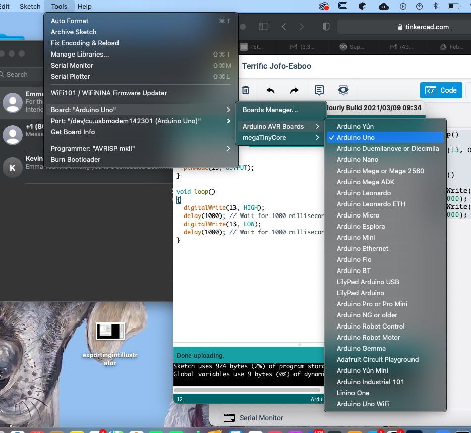
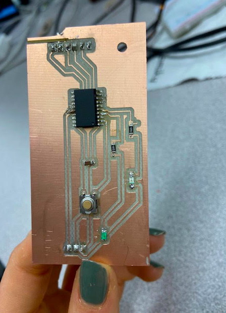
Programming ATTiny1616 using arduino in multiple IDEs I used the software Arduino and Visual Studio Code to program my ATTiny1616 and the Arduino Uno board.
Here we are with our proper protection!
But before this I had to create my code. I did this by first experimenting with arduino tinkercad
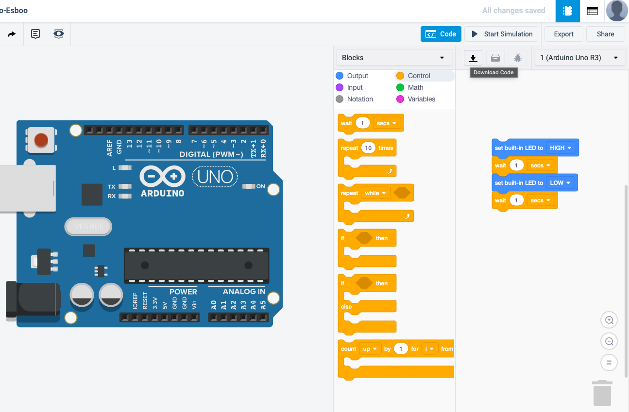
Here I am using the block code setting in arduino tinkercad to get used to how this coding formate works with leds
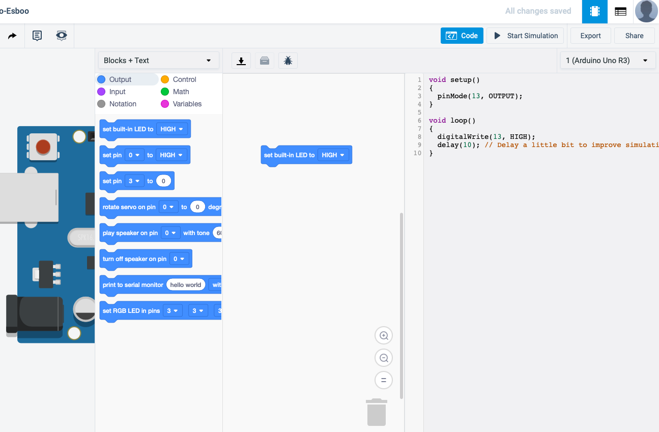
Here is how my block code translated into c++
Making something Big!
Brandon transformed our design in fusion 360, Here are the finished photos And design files.
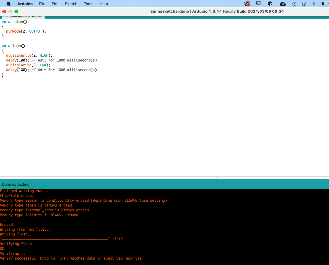
Then I copy and pasted this code into arduino and pressed run.
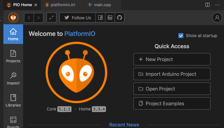
Then I downloaded the Visual Studio Code IDE
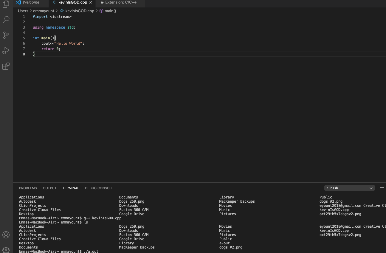
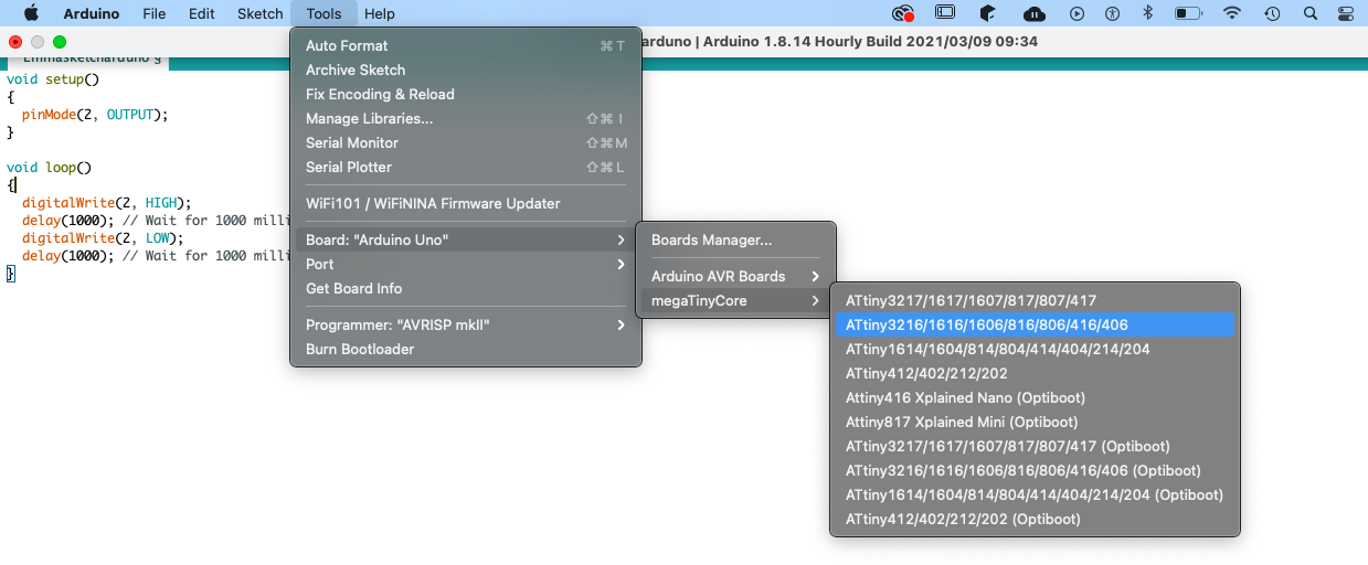
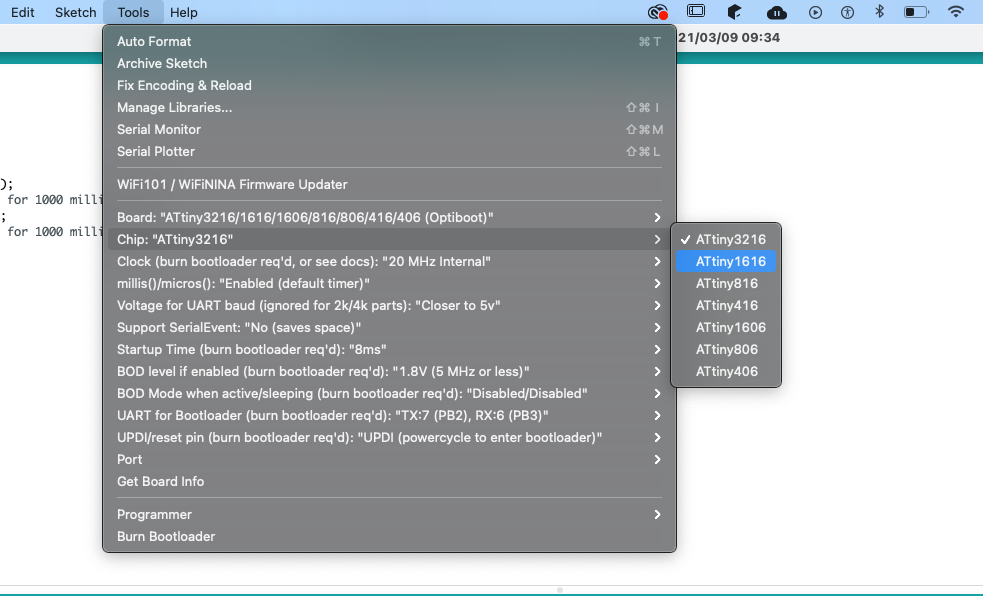
Here I am adding in my code into the workspace and maing sure my tool settings are all correct for the board and micro-controler I was using.
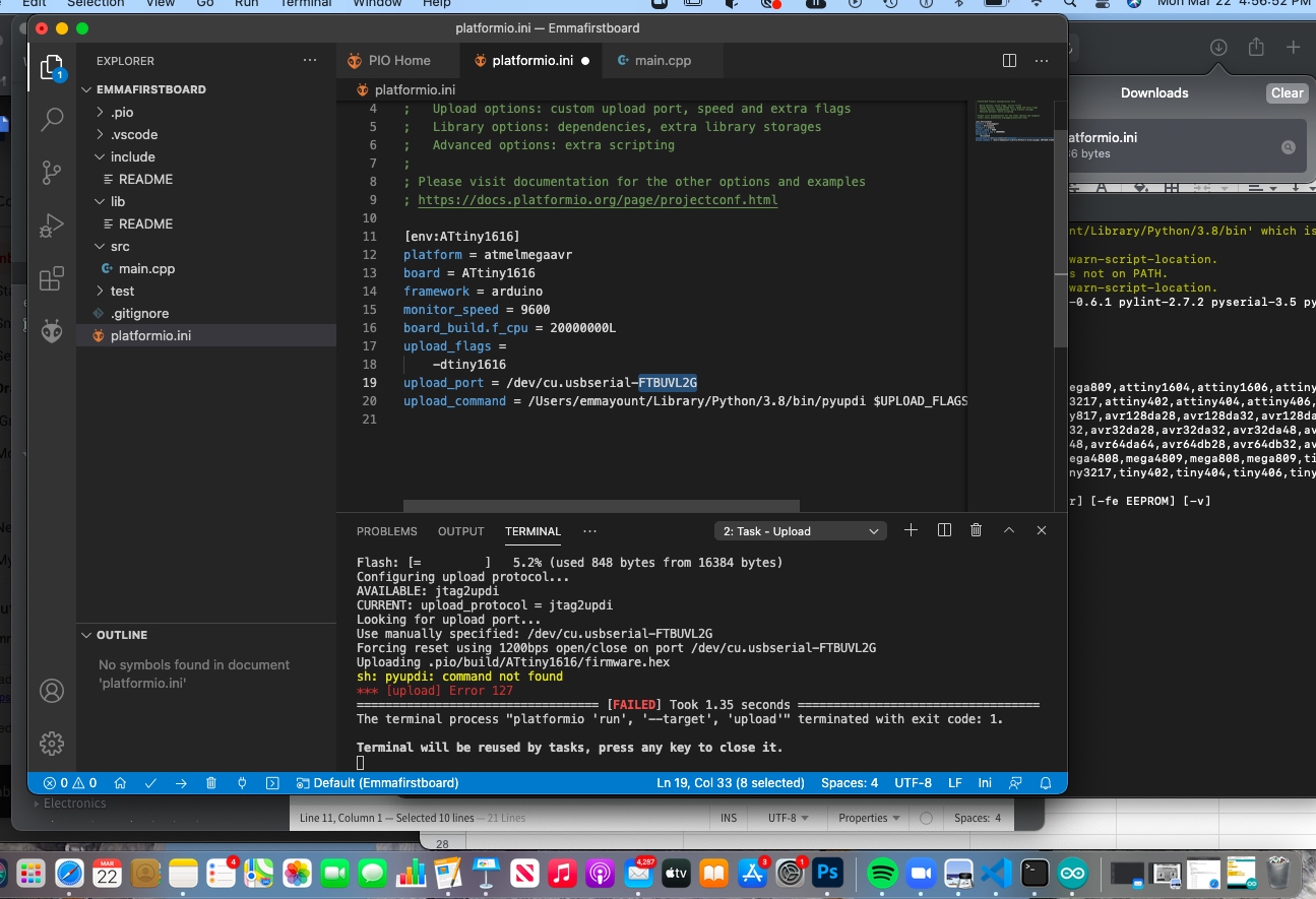
But as soon as I ran the code I got this error message.
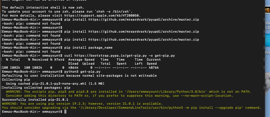
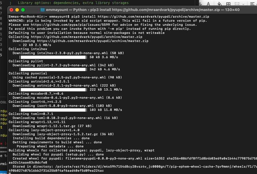
I then had to follow these instruction (link here) to install python to allow the program to run

Finally we realised I needed to hit the command retrieve pip3 since I was prevoulsy hitting the commend to retrieve a diffrent version of python and my updated mac was causing issues understanding which verion of python I needed. We put everything together and this was the result.
I ented this command into the visual Studio Code under my previous code that can also be found here: Here is my code! Here is the link to the directions I followed to SETTING UP THE PROGRAMMING INTERFACE and INSTALL PYUPDI link here
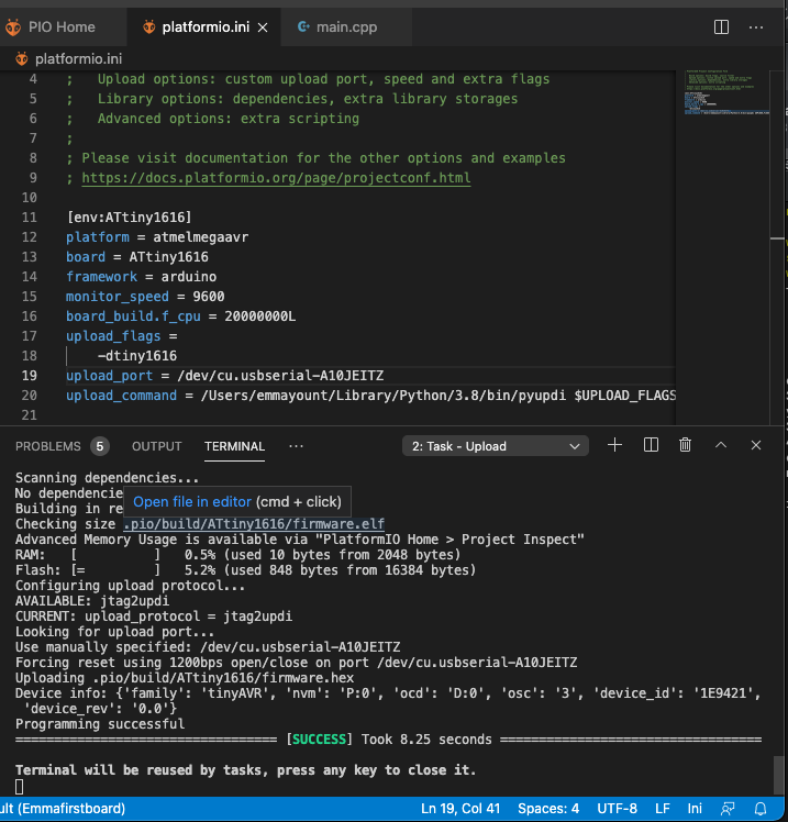
Here is the link to "hero video" of my programed board blinking the led lights in a cool way!link here
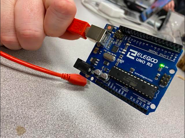
For the Arduino Uno Board I completed the same steps but changed the tool settings to function for the Uno instead of 1616
