
Summary
A fun week and finally learning to use a 3D printer (and scanner)! Using Fusion360 to make a design based on the limitations of a 3D printer, getting the file ready for the printer via ‘slicing’ software, and finally exporting to ‘g-code’ to be printed. And then a long wait!
What I thought I knew before
Nothing about 3D printers / slicers or scanners.
Learning Outcomes
Theory and use of things i learnt from this assignment:
- Identify the advantages and limitations of 3D printing.
- Apply design methods and production processes to show your understanding of 3D printing.
- Demonstrate how scanning technology can be used to digitize object(s).
Lessons to take away
It takes a long time to print anything!!! Print times are measured in hours!
3D Printer

(Original) Prusa i3 MK3+
| SPEC | VALUE |
|---|---|
| Max-work area (X) | 25 mm |
| Max-work area (Y) | 21 mm |
| Max-work area (Z) | 21 mm |
| Min-layer height | 0.05 mm |
| Nozzle (dia) | 0.4 mm |
| Filament (dia) | 1.75 mm |
| Max-travel speed | 200 mm/s |
| POSSIBLE MATERIALS | |
|---|---|
| Plastics | Prusament PLA |
| ABS | |
| PET | |
| HIPS | |
| Flex PP | |
| Ninjaflex | |
| Laywood | |
| Laybrick | |
| Nylon | |
| Bamboofill | |
| Bronzefill | |
| ASA | |
| T-Glase | |
| Carbon-fibres enhanced filaments | |
| Polycarbonates |
Risk Assessment
| RISK | WHO IS AFFECTED | CONTROL MEASURES | RATING | DEFENSIVE MEASURES |
|---|---|---|---|---|
| Appendage damage/burning | You | This example is enclosed in a self-made cabinet. | LOW. | Don’t try to place parts of the body into the machine while the printer head is running. |
| Lung damage from the fumes of the melting material | You | None | LOW/MED (depending on the material) | Close the cabinet, and don’t spend too much time next to the machine. |
| Risk of fire | You | Smoke alarm inside the cabinet. | LOW | Check progress of printing job regularly. |
Most used settings
| SETTING | VALUE |
|---|---|
| Nozzle | 0.4 mm |
| Filament | PLA |
| Z axis | -0.1 mm |
Limitations (PLA)
| TEST | VALUE |
|---|---|
| Overhang Limit Long | 75 ° |
| Overhang limit short | 65 ° |
| Bridging 25mm | 25 mm |
| Stringing test | no strings |
| Hole test 2/3/4mm | All fine |
| Rectangle test 2/3/4mm | All fine |
| Scale test: vertical | 1.9 to 2.0 mm |
| Scale test: horizontal | 2.0 to 2.1 mm |
| Diameter 6 & 8 | Good |
Guide
Calibrate fully after moving the machine: Using ‘Wizard’ function, the machine runs through all the calibration tests in its menu, ensuring that everything is calibrated to the machine’s new position.
Clean bed before printing: To ensure the best possible surface on which the filament will attach, it is advised to clean the surface of contaminants with something like glass cleaner.
Check filament is loaded (and not twisted) and ready to go: Any obstruction to the path of the filament could stop the feeding of the filament and interrupt the print job. Use the machine controls to load the filament and run any tests to confirm a clean nozzle with good flow.
‘unfeed’ filament after use: In order to preserve the life of the nozzle, the filament and ensure a clean extrude on the next print job, it is advised to ‘unfeed’ the filament from the machine when whenever a print job is completed. The filament should be returned to a re-sealable bag and stored with care to the environment’s moisture and humidity.
Operating instructions
- Calibrate. First feed in the filament into the machine using the machines functions.
Go through the different calibration / tests that you feel necessary to confirm that the machine is primed and ready to print.
- Add file to slicer -> export to ‘g-code’. Using a ‘Slicing’ software program, generic or proprietary to the particular machine you’re using, load up the design file (.e.g. .STL file).
Place the design on the ‘work bed’, rotate, position and any other adjustments you may need. Using the ‘Simple’ presets, choose which printer settings, filament type and printer you are using. Choose if you want the program to automatically add supports and how much ‘infill’ to your model.
‘Slice’ the model and save the file as a ‘g-code’ file.
- Insert SD card into machine and print. Transfer the ‘g-code’ file to the machine via an SD card, and run the print job when confident all the settings are correct.
Group Assignment

- Test the design rules for your printer(s)
- Document your work and explain what are the limits of your printer(s) (in a group or individually)
What we did
We downloaded a ‘calibration’ model from Thingiverse that had a combination of little tests for the printer in one.
Thingiverse Image from Lucia
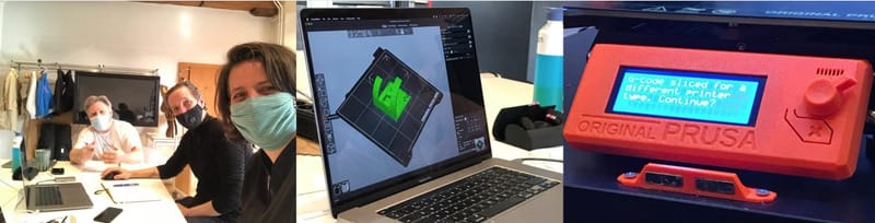
First we feed in the filament into the machine using the machines functions.
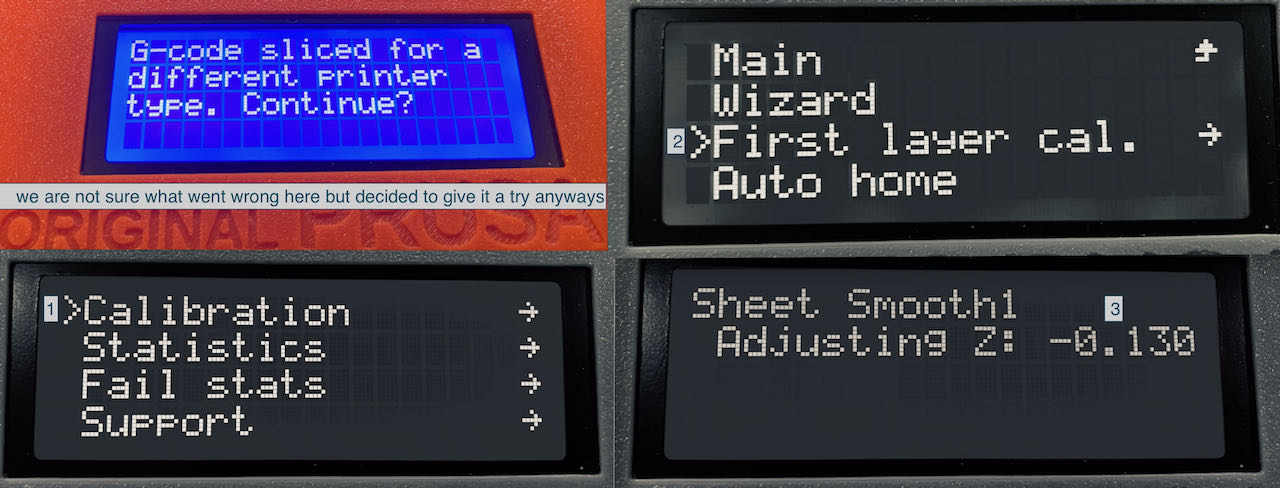
And then tried to calibrate the ‘Z-axis 1st layer calibration’. It took us a few different tries lowering the Z-axis to get the extruding filament to reach the bed. We found the setting ‘-0.1mm’ allowed the filament to extrude directly onto the bed and fuse multiple close lines together into one piece.
Calibrating the Z-Axis Image from Lucia
We placed the file into the machine’s ‘slicer’ software, and positioned the design on the bed with ‘placed on face’. This would convert the 3D model into ‘gCode’ horizontal slices for the machine to workout what route the nozzle shall take.
Using the simple mode, we chose the filament, printer and print settings (0.2mm Quality), and no supports and 100% infill. This test piece needs no help from the software, as we want to see it fail. We checked the settings in the software by changing to ‘expert’ mode - but also out of curiosity.
We ‘sliced’ the model and saved the file as a ‘g-code’ file on to an SD file.
We inserted the SD card into the 3D printer and tried to run the print job. We received a ‘File made for another printer’ error. Thinking we had done everything correctly, and the problem most likely being that the machine’s firmware wasn’t the latest version, we carried on with the print.
Prusa problem Image from Loes
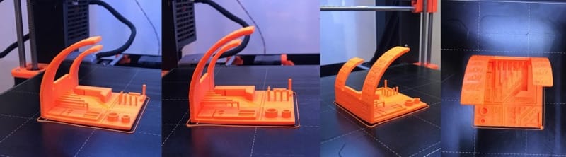
We checked that the first couple of layers firmly adhered to the heated work bed, and let it run, knowing that the most difficult part was over. Regular checks followed, and we noticed after a while that one corner had lifted off the bed for some reason. As we couldn’t do much we allowed it to carry on and see what the effects were at the end.
After 3 hours and 8 minutes it finished!
Finished group print Image from Lucia
| SETTING | VALUE |
|---|---|
| Z-axis level | -1.00 |
| Print Setting | 0.2mm Quality |
| Filament | Prusament Filament |
| Printer | Original Prusa i3 MK3S |
| Supports | None |
| infill | 100% |
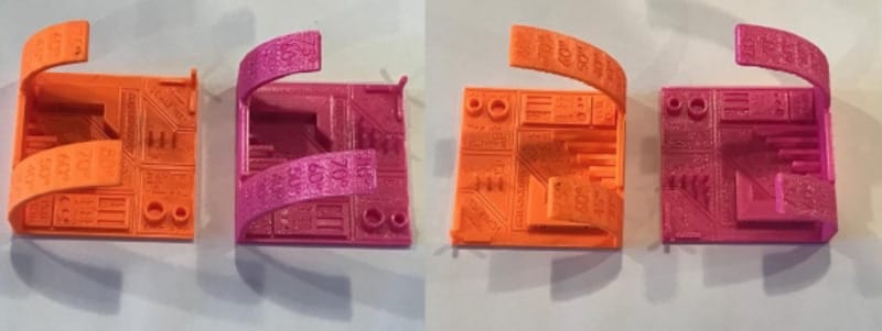
Since there were 2 different makes of 3D printer the part of Monday group printed the same model on the Ultimaker machine to compare quality and their results.
Print comparisons Image from Lucia
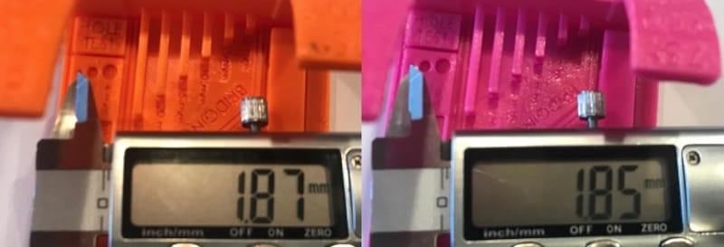
Some of the individual printer tests on the model were either labelled or fairly obvious at what they were testing, while others weren’t (or you couldn’t get any measuring instruments near them). So it was interesting to see that a 2mm hole left by the printers didn’t actually measure up to 2 mm, and were different between the 2 machines.
Measurements Image from Lucia
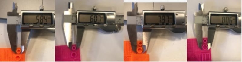
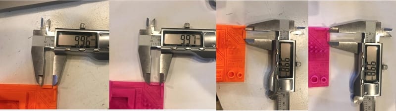
As with the following examples, some measurements between the prints were large on one machine, whereas other measurements were smaller on the same machine in comparison. There didn’t seem to be one machine you could say outright that it was more accurate or consistently accurate than the other.
Measurements 1 Image from Lucia
Measurements 2 Image from Lucia
(But i actually favour the Prusa as it seems easier to use and the quality of print seems higher than the Ultimaker.)
Mistakes & Issues
Getting the extruding nozzle close enough to the bed. It took several attempts at the ‘Z-Axis 1st layer calibration’ test to get the filament to be extruded directly on the hot plate. THe evidence of which is that the 10mm filled square of lines at the end of the test has melted together to form one piece.
Print lifted at one corner. After a while, one corner of the piece lifted off the work bed. It had previously had a good attachment with the bed from the first layer. We are unsure why this occurred.
A ‘File made for another printer’ error. At some point in the checking of settings in the Slicer software, we visually chose the image of the printer we had. Since the models look very similar, we picked the wrong one. But since they were similar specs we carried on with the print.
Individual Assignment #1

- Design and 3D print an object (small, few cm 3, limited by printer time) that could not be easily made subtractively.
- 3D scan an object, try to prepare it for printing (and optionally print it).
What I did #1
The inspiration for my model came from a test piece that the instructor had printed previously. The tiny piece was an engine, cut away to show its 3 cylinders and pistons that could actually move when turned. The amazing thing was that all the movign parts had been printed in one go. No assembly needed!
With that in mind i wanted to design something that was a little mechanical, had moving parts, printed in one piece, but purposeful at the same time. It also had to be designed with the printer’s limitations in mind.
I came up with the idea of a musical box. Due to the small amount of machine time this model would have to be small. Therefore a lot of the measurements would be at (or close to) the limits of the printer.
I designed the model in Fusion360, taking care to try and minimise the amount of material and time needed to print.

Steps i took included:
- Hollowing out the sound box, making the thickness of all walls the ‘minimum wall thickness’.
- The ‘notes’ of musical comb would be as thin as possible, also to increase flexibility and the likely hood of actually working.
- Cutting holes through large faces where structures allowed to save weight.
- Fillet/chamfer all edges to reduce weight a little more, and add extra structural integrity/reduce stress in vulnerable places.

Features:
- The crank handle has an angle of 70' (instead of 90', so that no supports aren’t needed when printing).
- The musical comb has a lowest note based on the length of the longest unsupported overhang possible. There are 5 notes in the scale, mathematically (equally) dividing an octave. (The highest note is half the length of the lowest).
- A sound box underneath the mechanism (like a guitar), to give it the best chance of being able to resonate and be heard by itself.
- Placing the model on it’s side to be printed turned out to be the quickest and with the least amount of supports needed (if at all)

Mistakes & Issues

Supports. Or lack of them on the first try. Some features need some support material to ensure that they (for example) can stretch horizontally, when they have no bridge to attach to.
Too far for unsupported. 30mm was too far to stretch the filament horizontally across, even if it had some support from the shorter filament next to it, e.g. the cap of a cylinder.
Minimum gap between parts. This was far too small in the first try, meaning all the parts were joined together.
Some deformation with long vertical walls. There was some bowing in the centre of the long high wall. This was due to it being unsupported in anyway. Infill should solve that problem.
What I did #2
What I changed:
Add supports. in the Prusa Slicing software i’m going to add supports to the first tooth of the music comb and to the music drum through the holes in its supporting piece.

Increase the value of the separation between moving parts. To at least 0.2mm to match the resolution of the preset.

Infill. Adding ‘infill’ to the model will automatically create ‘ribs’ in the hidden places (e.g.the double walls), adding bridging points. This will be at the minimum settings as there were only a couple of places the model were near the limit of horizontal extrusion. It should eliminate any bowing on long vertical walls.

So I added 5% infill to the model and tried ‘painting’ in areas that i believed need support. This was pretty difficult as there were a few places where the overhang needed support but were difficult to get to because they were going to be a moving part. In the end i allowed the software to create the supporting structures itself. This left a cleaner looking support system, and would add the same amount of time to the original print time as my own attempt. I specified that it only added supports that were accessible via the base plate. Adding supports ‘everywhere’ instead would have added even more time and involve a lot of tricky cutting away of support material afterwards.
I also tried to cut the time and the amount of supports need by testing the model in different rotations on the work bed. But the model laying on it’s side was still the most efficient. The infill and supports did increase the print time from 2 hours 19 mins to just over 3 hours.

Once printed, i spent a bit of time with various sharp implements cutting all the support material away. The trickiest place being where the separation between the moving parts were. There were a few points that could be improved on the model:
- One corner lifted from the bed.
- There was too much separation between the drum’s shaft and the supports, allowing the drum to wiggle when you turn it.
- The separation of the teeth of the musical comb was difficult to achieve as they all wanted to stick together with the support material. Due to the thinness of the teeth the ends got a little damaged when removing the support material.
- One side of the posts on the drum had some trouble being printer. At 90' to the work bed, these really need some support to get a good finish. But this adds so much support material it will take a lot longer to print and post-process.

Future development
If I was to take this design further i would experiment in different ways to:
Minimise the distance needed between moving parts. At 2.5 times the print resolution settings (0.2 mm) there is a little more play in the moving parts than i had expected, i would be interested in finding out a minimum value without joining the parts.
Surprisingly robust design. Partly due to the mechanics of my design, the value of thickness I used for the walls, and the inherent material properties of PLA, the model was tougher than i had expected for a plastic model. I believe i can cut down the amount of material used (and therefore print time) and still retain enough strength and robustness.
Make the design as parametric as possible. Taking the time to make sure that the design was as parametric as possible would allow for easy creation of alternate versions of the music box, e.g. in the number of ‘notes’ it can have on the comb.
Design my own supports in the design. I would think with a bit more thinking and additions to my design I think there could reduce the need for so many supports. And therefore lowering the amount of print tme, materials used and ‘removal of supports’ time.
Print a range of music boxes. And put a FabLab Band together, do a world FabLab tour, gain a following, take over the universe.
Individual Assignment #2

- 3D scan an object, try to prepare it for printing (and optionally print it).
What I did

Having seen the trouble the instructor had demonstrating how to use the device hand help i decided to try a different approach. I attached the scanner to a microphone stand (used to hold a webcam for online demonstrations at the Waag) and set a rotating platform on the table. I placed my object (a vinyl art-toy) in the centre of the platform.
I started up the Windows machine and the 3D Sense software, clicking the scan type to ‘object’ mode. It recognised the boundaries of the object so i pressed ‘SCAN’.
All i had to do then was slowly turn the rotating platform. The object turned green as it turned showing that it had a good scan of that part of the object. Any parts weren’t picked up immediately (that stayed grey) i briefly rotated the platform in the opposite direction to try another scan.
To try and get coverage of the under cuts and the top of the model I adjusted the height of the microphone stand a couple of times to give another perspective.
When as much of the object as possible was green, I clicked on ‘Finish’ and gave it time to do its ‘magic’, and convert the scan into a model.
The ‘Solidify’ function managed to roughly fill in any holes that were in the model. After which it was ready to export to an .OBJ file for further work or printing in other software.
Mistakes & Issues
Tricky to use hand-held. So i used a microphone stand to attach the scanner to, and placed the object on a rotating platform. Worked much better!
Under cuts and ‘caps’ difficult to scan. It was difficult to scan ‘under cuts’ and ‘tops’ of objects without losing the tracking and having to start again.
CONCLUSION
There are a lot of variables that can go wrong in 3D printing - only from experience and testing over a long period will i get a good mastery of these. But I feel confident that i’m on the right path to this after this week. I see a bright, shiny future for myself now. Full of small plastic objects!