14. Networking and communications
This week I worked on defining my final project idea and started to getting used to the documentation process.
Individual assignment:
design, build, and connect wired or wireless node(s) with network or bus addresses.
I2C
For my first connection, I decided to try the I2C Communication Protocol. With this protocol, you can connect multiple slaves to a single master (like SPI) and you can have multiple masters controlling single, or multiple slaves.
Similar to the UART communication, I2C uses only 2 wries to transmit data: SCL and SDA.
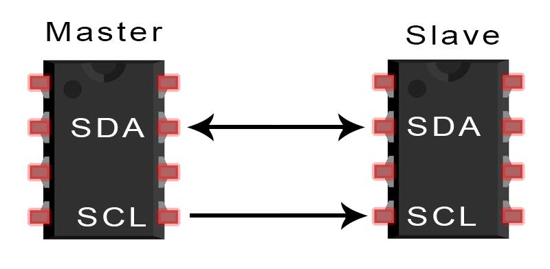
SDA (Serial Data) is how the master and slave to send and receive data.
SCL (Serial Clock) is what carries the clock signal.
Arduino Master, Arduino Slave
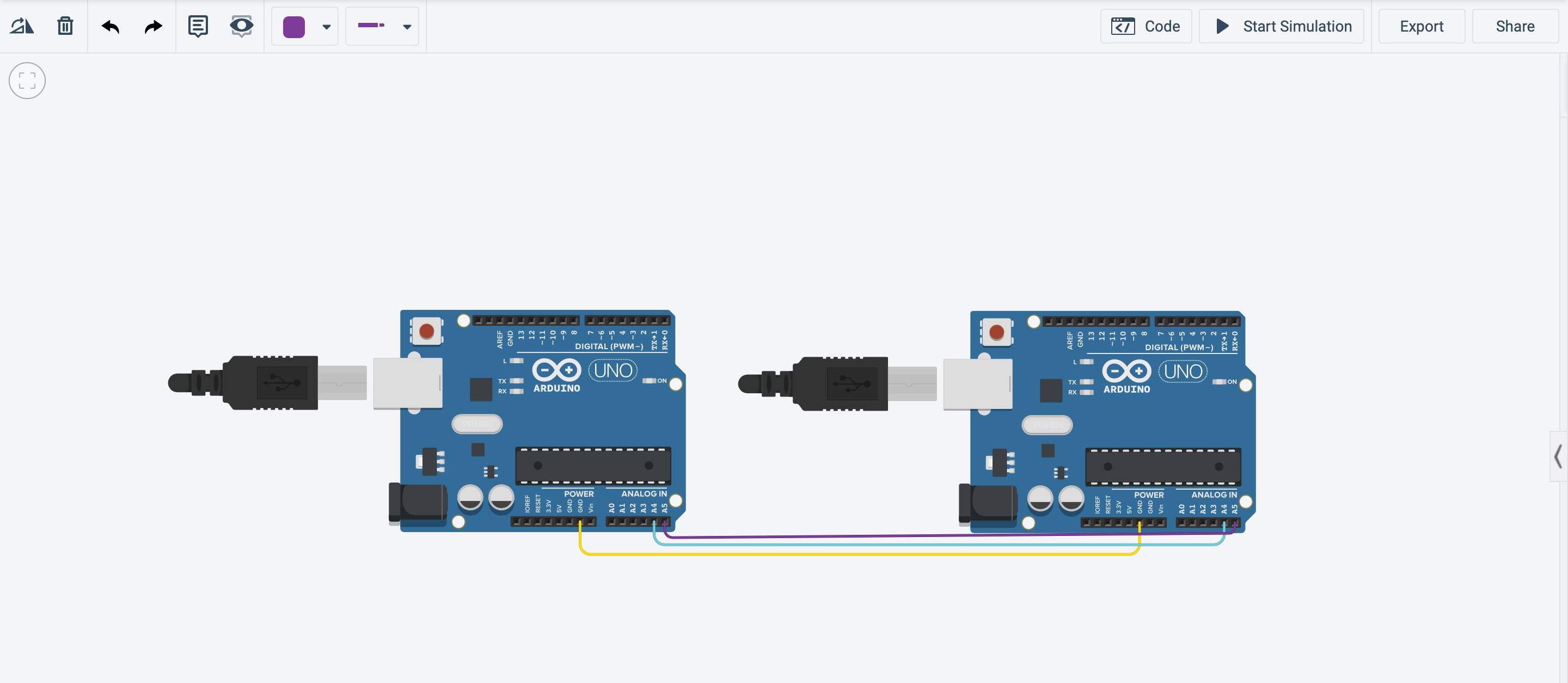
First, I prepared a simulation on Tinkercad using two arduinos and establishing the I2C connection by connecting the SCL and SDA. This simulation will be exactly how the real connection will be made, which is why its such a helpful step. I had only one slave and one master, both which are Arduino UNOs. In the Arduino, the A4 pin is the (SDA) and the A5 is the (SCL), so I connected those alongside the GND and VCC.
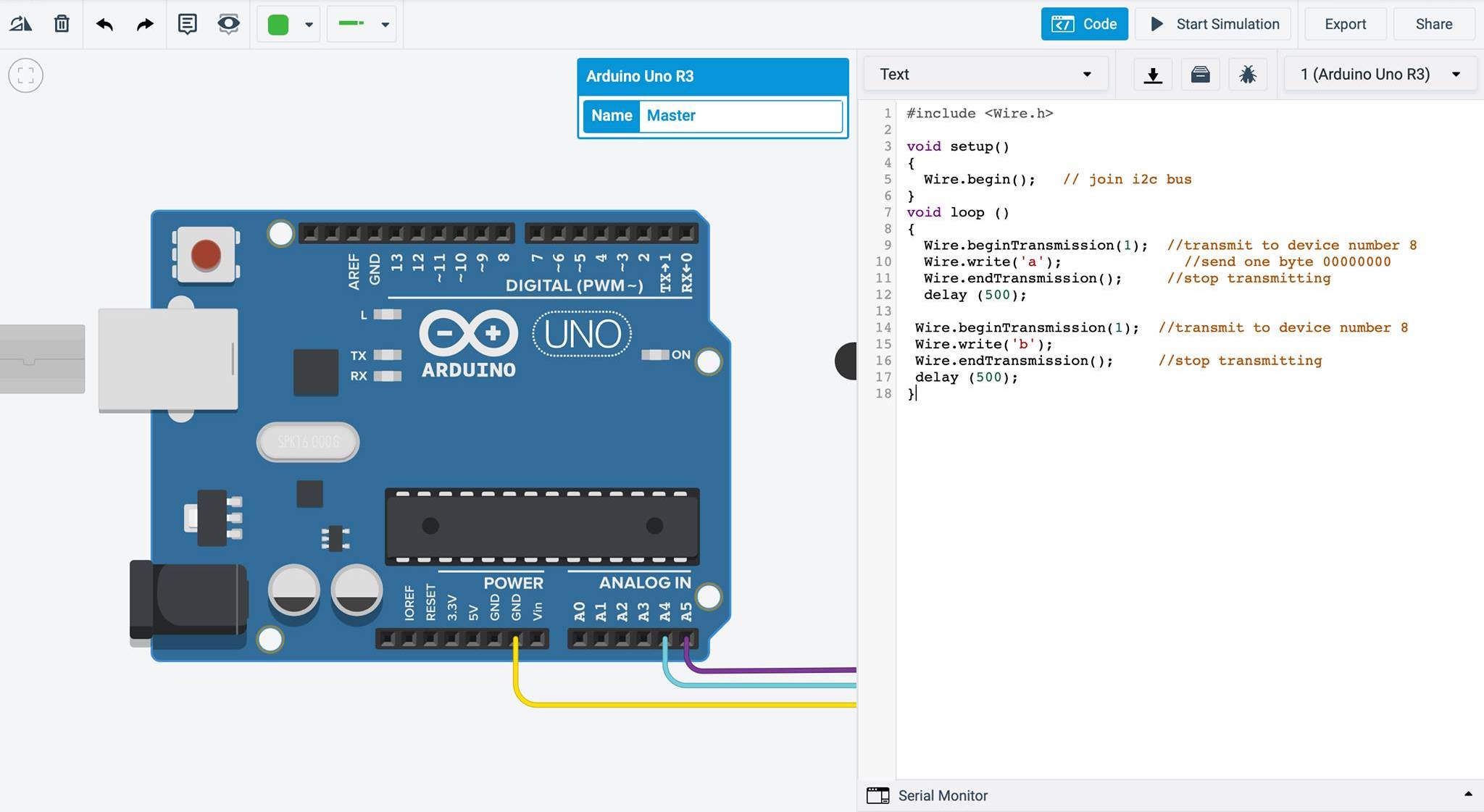
Then, I started uploading the code for the master and slave board. Using the Wire Library you can find the functions and what they mean, but the code itself explains it too.
Master
Slave
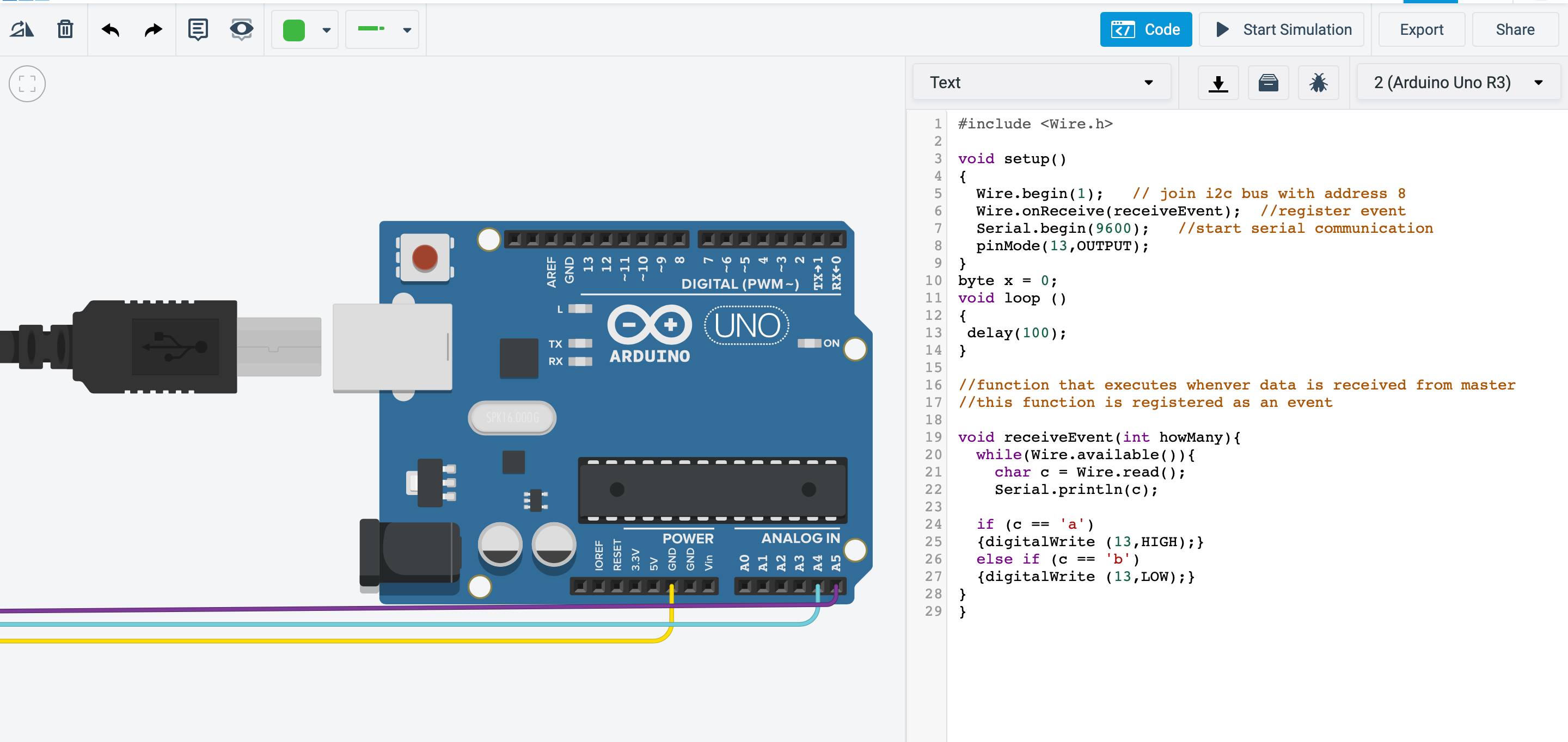
Upon starting the simulation, you can see the LED blinking everytime the letter ‘a’ is transmitted, which is every (100) milliseconds.
I went to the lab, formed the connections on two Arduinos the exact way it was done in Tinkercad, and I got the same results!
Arduino Master, ATMEGA Slave
Just like the simulation, we must first establish the I2C connection (SCL and SDA + GND). For that we look at the ATMEGA pinout and check the pins.
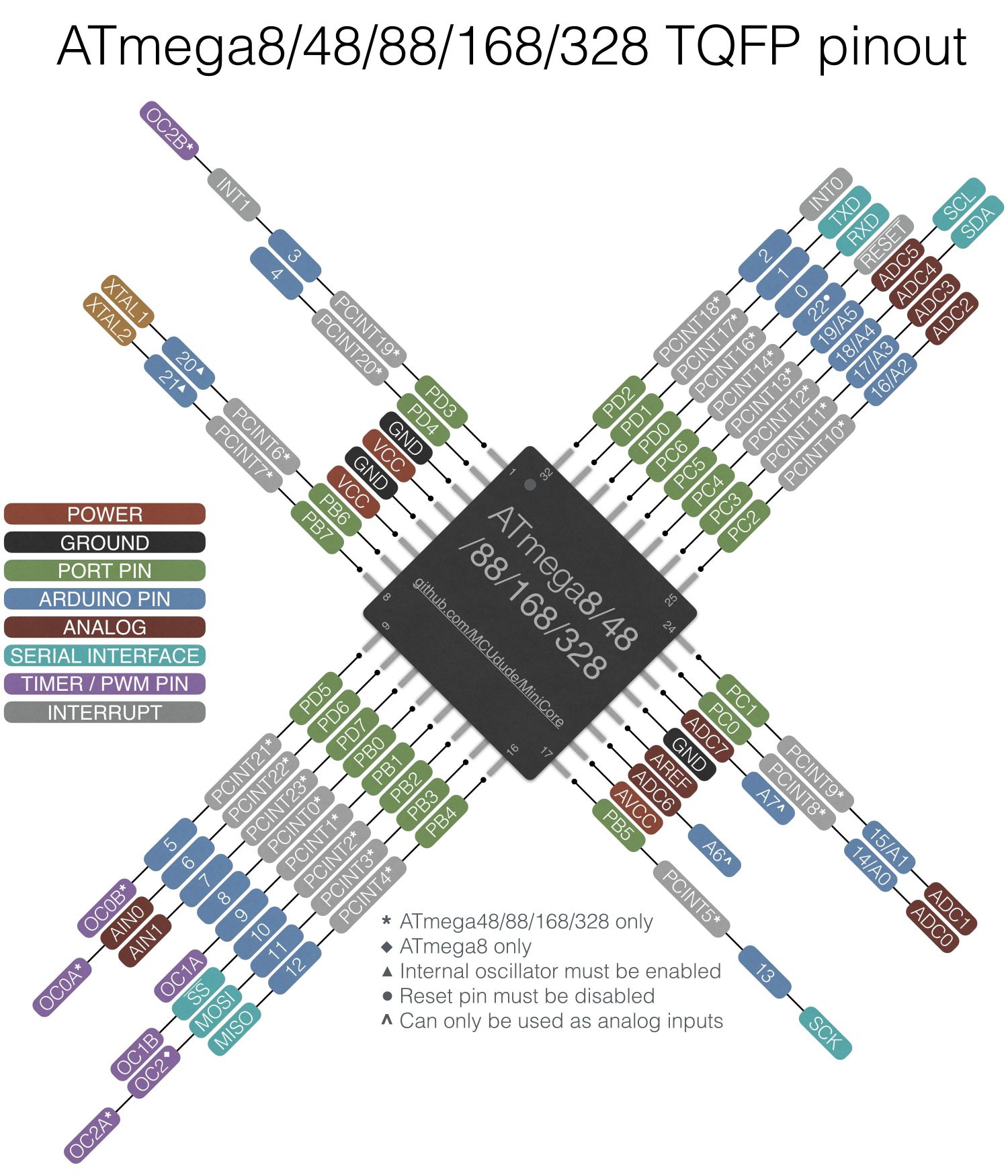
From the pinout we can identify that the PC5 and PC4 are the SCL and SDA, so we will be using those pins for the connection.
Then using Arduino IDE, we launch the code onto the boards: Arduino as the master, and ATMEGA as the slave.
ATtiny Master, Arduino Slave
Yet again, we form the connections between the two boards, and for that we look at the ATtiny pinout to identify the SCL and SDA pins.
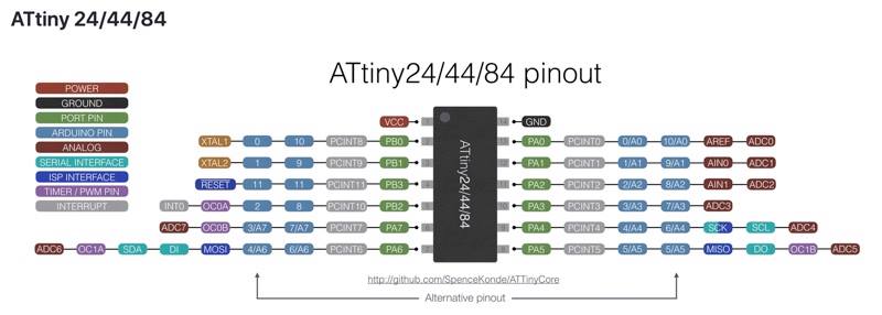
We can identify that PA4 and PA6 are the pins we need for the connection as they are the SCL and SDA. So, we form the connections and launch the codes.