10. Molding and casting
Link to group assignment page.
This week I worked casting pieces I will use in my final project.
Individual assignment: design a 3D mould around the stock and tooling that you’ll be using, mill it (rough cut + (at least) three-axis finish cut), and use it to cast parts.
Designing
For this assignment, I had many ideas, and I started to sketch them out; however, I settled for little gemstones that I think will add texture to my final project.
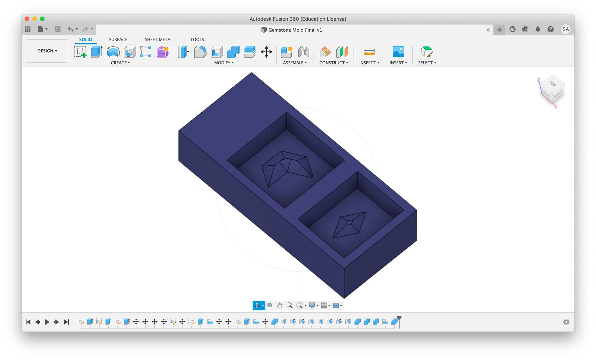
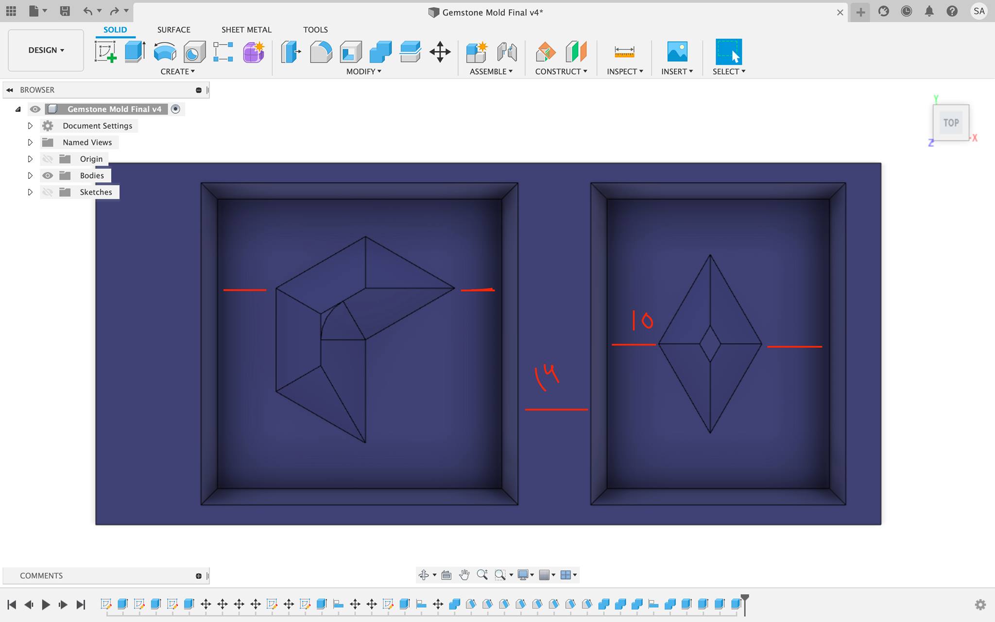
First, I designed the gemstones using the inscribed polygon tool, and extruded them to be a few millimeters thick. Then, I sketched the machinable wax with dimensions according to the block the instructors provided for us. After that, I moved the two gemstones to be placed above the wax in appropiate places using the move tool. I drew out squares around the gemstones with 10mm empty space from each side and extruded it down to around 15mm. Then, using the allign tool, I alligned the bottom face of the gemstones to the top face of the pockets and by then, everything was in place. I also created drafts on each face of the inner pockets to ensure the collet doesn’t bump into anything when milling; however, since my design wasn’t extruded too deep, it didn’t really matter.
Extracting toolpaths
Fusion 360 also provides CAM services, so by switching from the Design wokrspace to the Manufacturing, we can extract the toolpaths from Fusion itself. The first step to extract toolpaths is to add the tools. So, I hovered to the Tool Library under the Manage controls on the ribbon menu bar, and then selected the name of the project i’m working on from the list on the right. Then I pressed the ‘+’ sign to start adding the tools I’ll need.
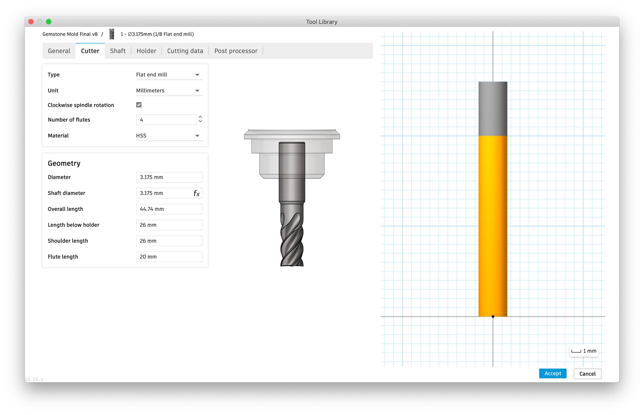
I started by adding the flat end mill. I adjusted it’s setting according to the bit available at the lab. Hence:
-
1/8 inch diamater
-
4 Flutes
-
44.74mm overall length
-
20mm Flute length
Length below holder and shoulder length is to be changed later, so it doesn’t matter what number we put atm.
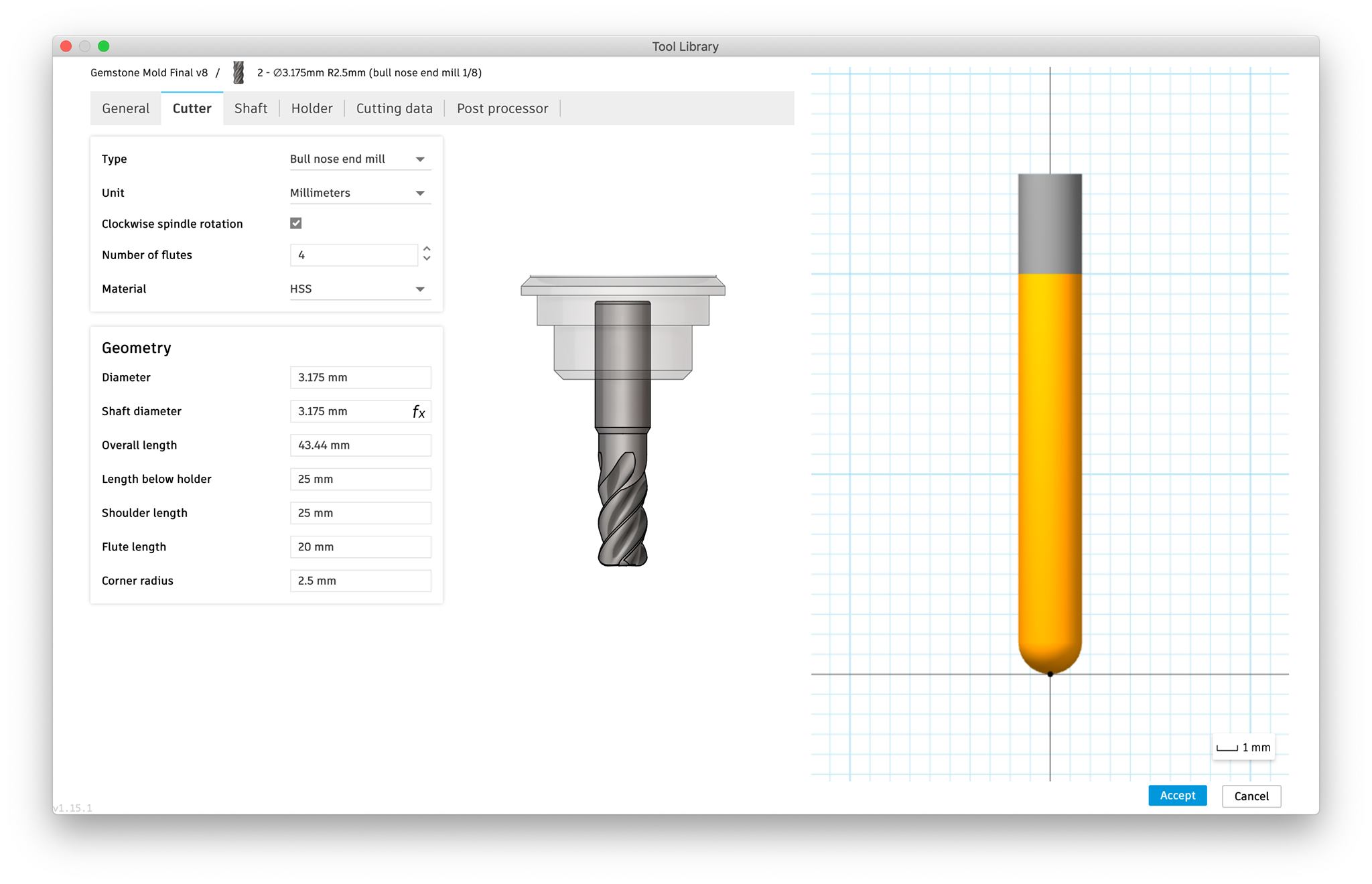
Following the same steps, I added the second tool, the bull nose end mill.
After adding the tools we create a setup that will identify the key point for the milling process. So, in the Setup controls > New setup make sure the operation is at milling and then under the “Work Coordinate System”, I changed the orientation to Select Z axis/plane & X axis and chose the respective axes. For the origin, I kept it at stock box point, and chose the most bottom and left point on the stock.
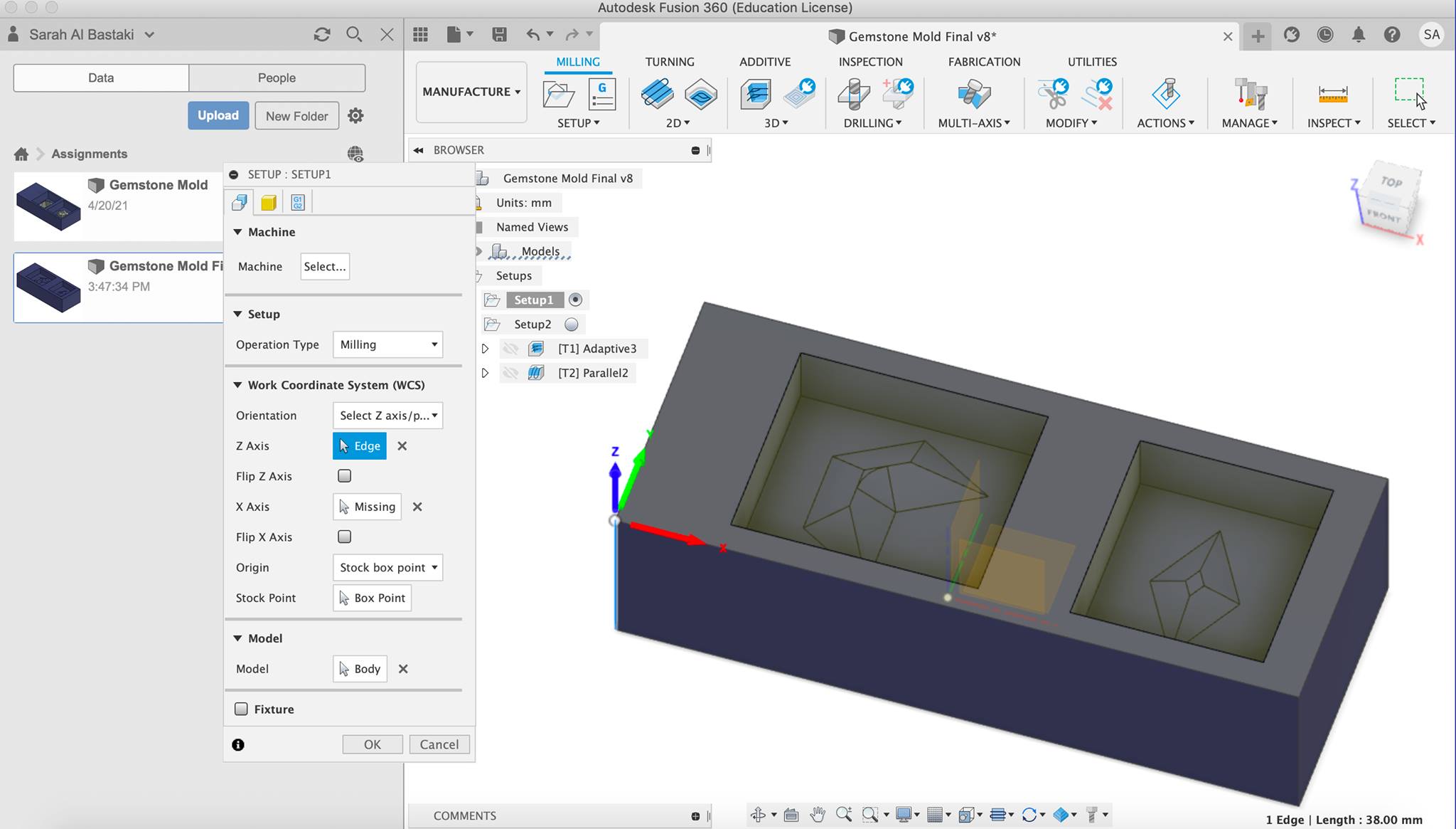
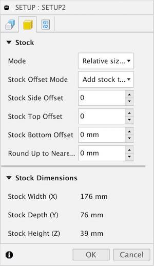
For the stock tab, I changed all the offsets to 0mm, and I pressed OK indicating the end of the setup.
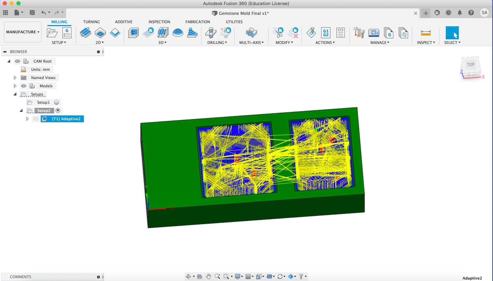
Now that the tools and setup is done, we can start generating the actual toolpaths. The milling process will be split into two parts: the adaptive clearing and the parallel. The adaptive will start milling out the unnecesary areas roughly just to clear out the space, and the parallel will smoothen out the molds with more precision.
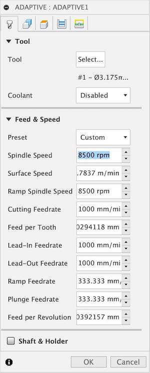
First, we generate the adaptive clearing toolpath by going to the 3D tab in the menu ribbon bar, and in the drop-drown list we find Adaptive Clearing. In the Tool tab, we select the tool Flat end mill that we added later, and disable the coolant. Then, we change the Spindle Speed to 8500 rpm (respective to our SRM-20).
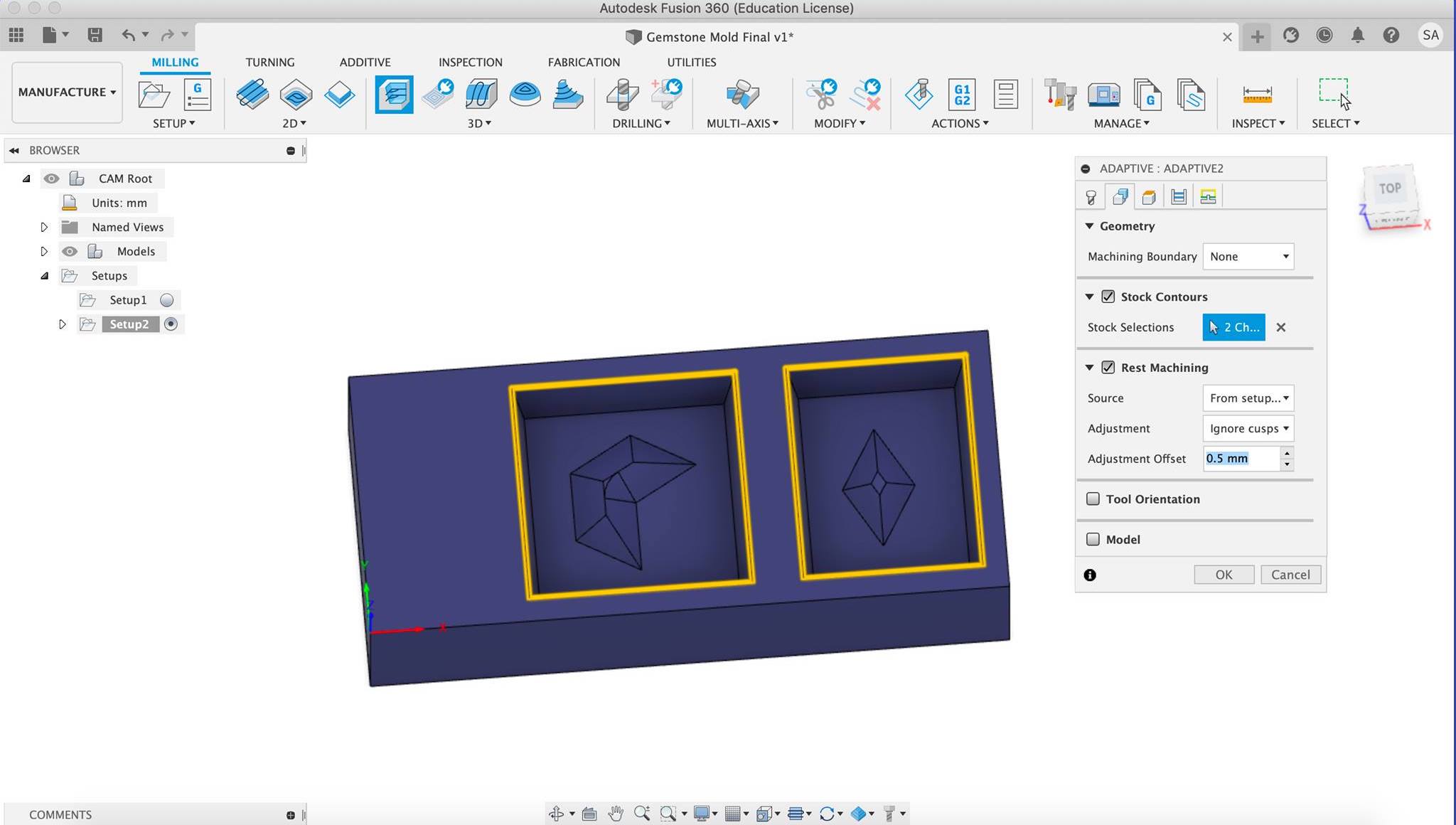
In the geometry tab, we select the two squares that border our pockets. Selecting the geometry is completely subjective as it all depends on what can you choose to get your milling right.
Then we move to the passes, it is important to first set the Maxmum Roughing Stepover to a number smaller than the diameter of your bit. On my first try of milling the mold, I forgot to do that. A LOUD noise was produced by the SRM-20 and my instructor had to rush to it, or else serious damage could’ve been done to the machine. Below the Maxmum Roughing Stepover sits the Fine Stepdown. This controls how fine and precise your milling will be. Since this is just the adaptive clearing, with aims of being just a rough cut, 0.2mm was sufficient. Press OK, and wait for your toolpaths to generate.

After they generate, you can make sure of whether they turned out right using the stimulate options. In the Info tab of the stimulate window, you can also find the time it’ll require to finish the milling. My toolpaths seemed to have worked out perfectly, but after milling I discovered an issue (to be discussed later).
Similar to the adaptive clearing, 3D > Parallel, select the bull nose end mill, adjust the spindle speed and disable the coolant, adjust the geometry to select the object of your molding design - in my case the gemstones - then change the Stepover to 0.1mm as we need more precision in this one. Then press OK and wait for the toolpaths to generate, adn stimulate to make sure everything went well.
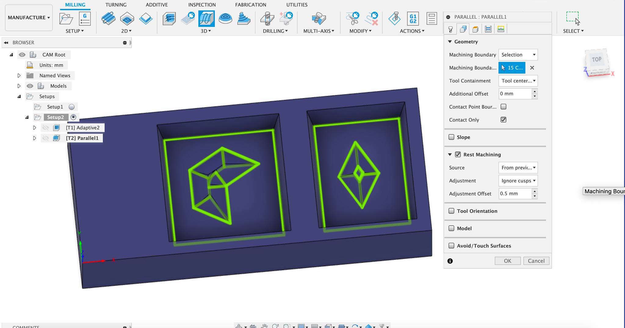
P.S after milling my first try, the parallel ended up not working properly, so make sure you do not overlook the stimulate step. To fix this, all you need to do is choose the geometry once again properly.
Milling
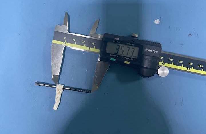
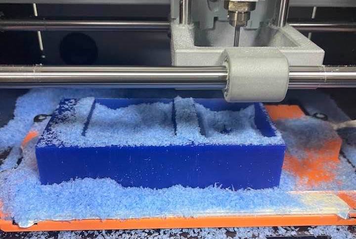
To mill the machine wax, I used the Roland SRM-20. Using double-sided tape, I stuck the machine wax to the metal piece (im not sure of the name honestly) and screwed it into the Roland. Then I moved the bit to the origin point (bottom left) and set that as the origin. I then changed the bit to the 1/8 Flat End Mill and set the Z origin point.
This is when it gets tricky, I added a piece of tape to the uppermost edge of the bit to mark where it is first exposed out of the holder. Then I took the bit out and measured the length below holder, which is from the start of the tape to the end of the bit. I then right clicked the adaptive clearing > edit tool and changed the length below holder and shoulder length to be the measurment I found - 1mm.
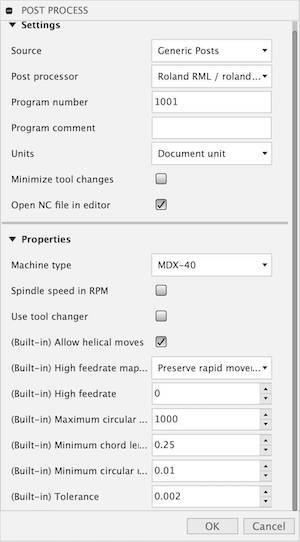
Wait for the new toolpath to generate then right click > post process. First I chose the format of the file I required which is the rml compatible with the SRM-20, then I changed the machine to MDX-40 because it is the closest to our Roland. Generate the file, and save it to your flash drive.
Then plug the bit back in and move the bit back to the origin you already set, and cut the file.
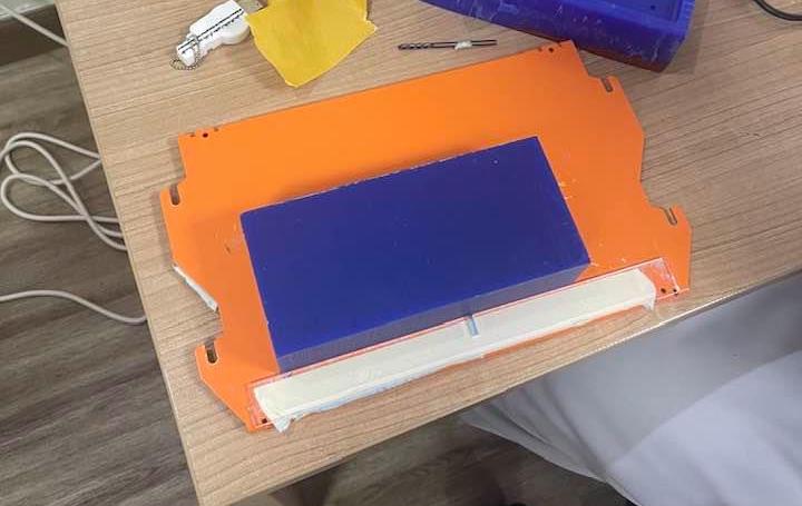
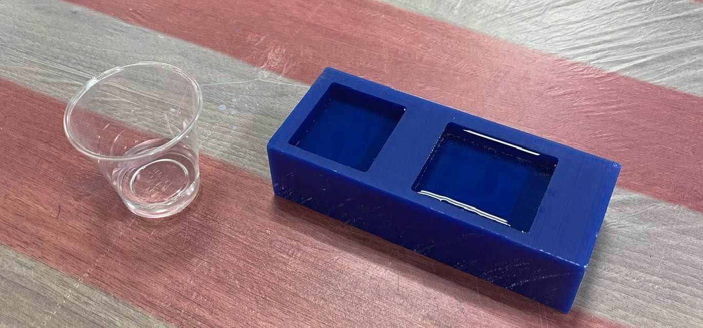
When this is done, I repeated the same steps for the parallel finishing and the final mold looked as follows…
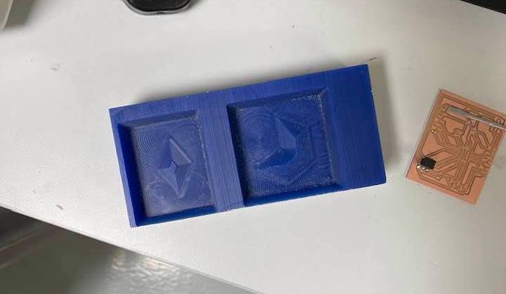
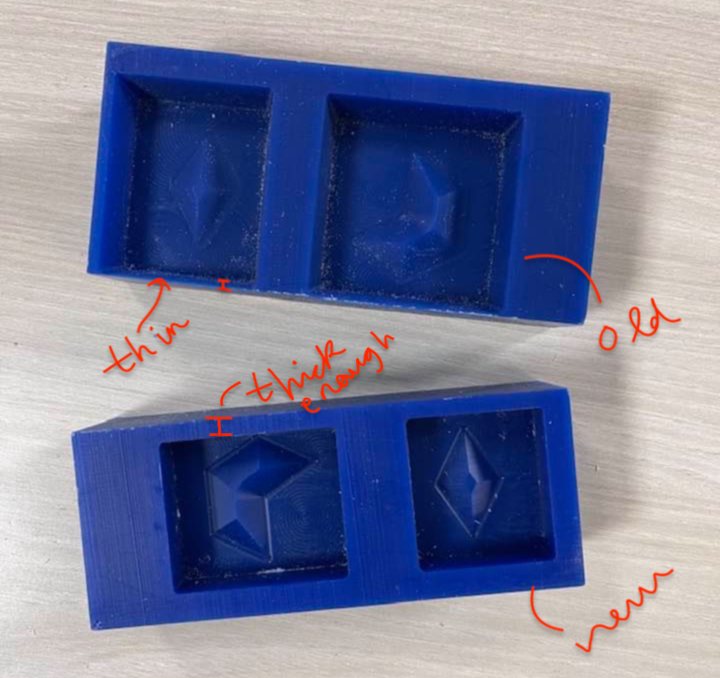
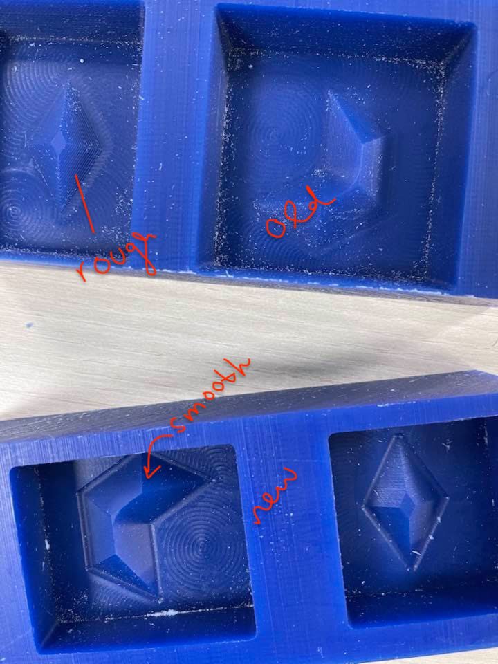
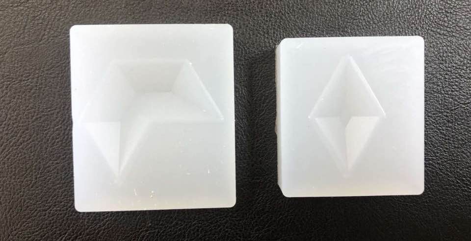
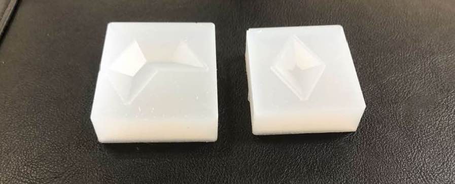
Although the picture isn’t quite clear, in the next one you can see that the parallel finishing didn’t really work as the surface of the gemstones isn’t very smooth. Also, one of the walls of the pockets was very thin, this was due to a design error in the size of the machine wax i drew. So, I fixed both issues, and milled another one. For the parallel I re-did the geometry selection, and for the thin wall issue, I just edited the dimensions. Below you can see a comparision between the new mold and the old.
Molding
After milling the machine wax, I used it to make a negative mold out of silicone that will then be used to cast the parts. All the solutions used in both the moulding and casting processes could be dangerous, therefore, I spent time carefully reading and following the safety measures suggested by the product’s manual.
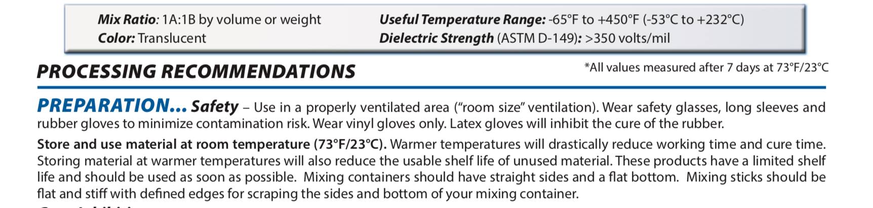
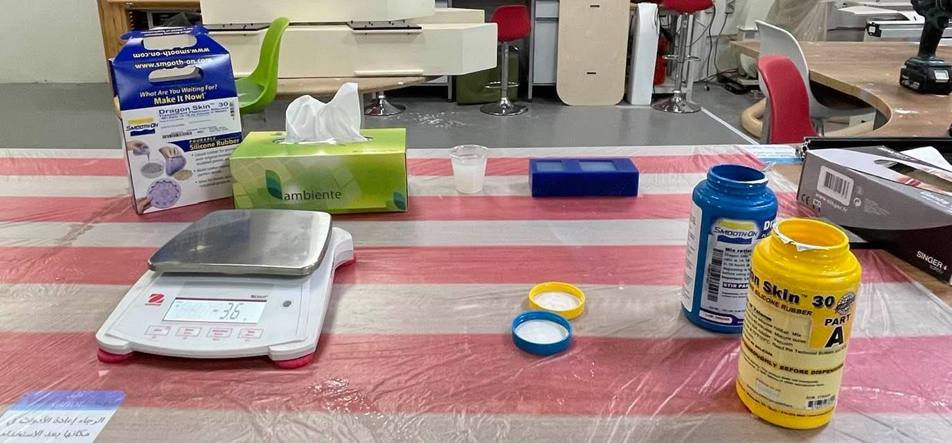
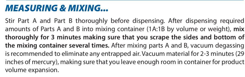
For my mold, I will be using the Smooth-On Dragon Skin 30 Translucent Platinum Silicone. The solutions consists of two parts: A & B. First, I read the instructions manual and followed the safety instructions below:
So, with my gloves, plastic apron, and face mask on, I started molding. The first step according to the manual was to stir Part A and Part B in their containers for a minute. This is done to just make sure everything is well incorporated.
Next, I needed to measure how much solution I’m going to need. To do that, I first measured the mass of an empty plastic drinking cup on a balance and zeroed it to that mass.
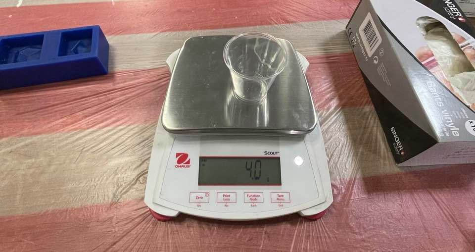
Then, I filled both pockets of my machine wax with water, and then transfered it back to the cup. That cup with water was then measured to find out how many grams of the solution I am going to need. Note that you can do this either by volume or mass, I chose to do it with mass.
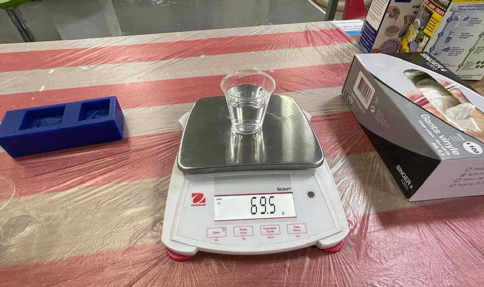
The instructions also inform you of the solution’s ratio which is a simple 1A:1B; in simple terms, equal parts of A and B.
Using that information, I split the total grams of solution needed (69.5 grams) into half (34.75), and poured an equal amount of part A and B till I achieved the total amount required.
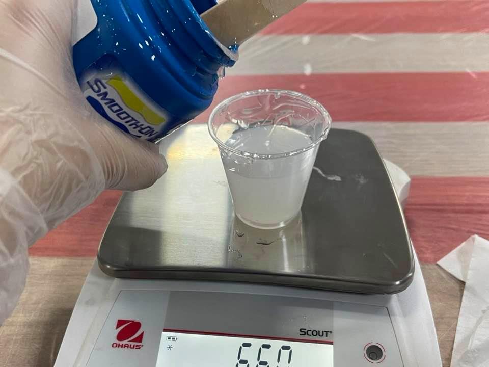
I then stired the mixture making sure I scrape the edges, and allowing the least amount of air bubbles to form. After a minute of mixing, I poured the silicone into the wax carefully, following the directions in the manual.

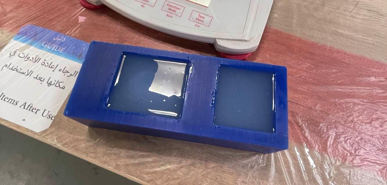
I honestly didn’t cure the mold the same way the manual asks for it. I left the mold to dry in room temperature overnight, and it came out looking very beautiful!
Casting
For casting the shapes, I used Epoxy Resin by ArtResin. I casted the diamonds two times: once in red and once in purple.
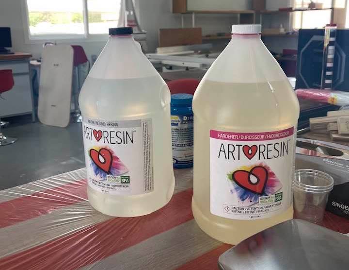
Following the infographic with the instructions, I started to create my mixture. I used a 1:1 ratio of resin to hardener and stirred it for around 3-4 minutes.
Then, I added a few drops of purple colorant also by ArtResin and mixed it into the mixture.
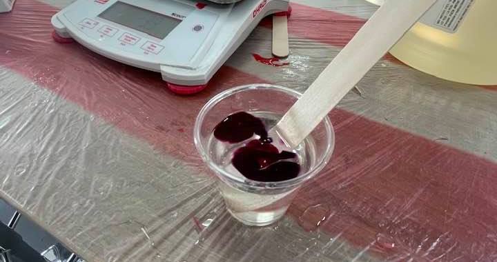
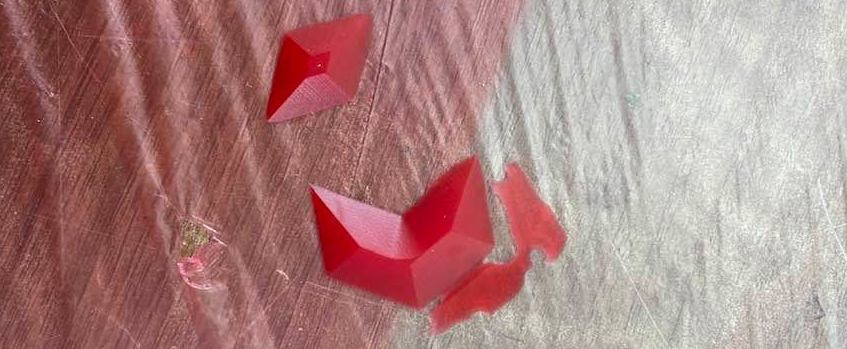
The rest is obvious; I poured the mixture into the mold, but this was so hard! Since my design is very thin, it was hard to control the pour and not overdo it. Hence, the very messy pour of resin.
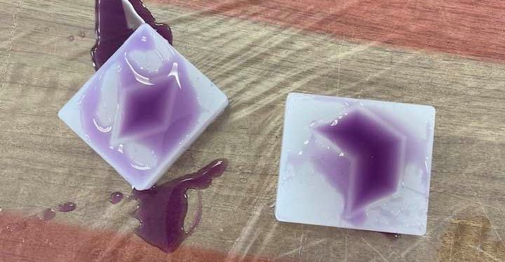
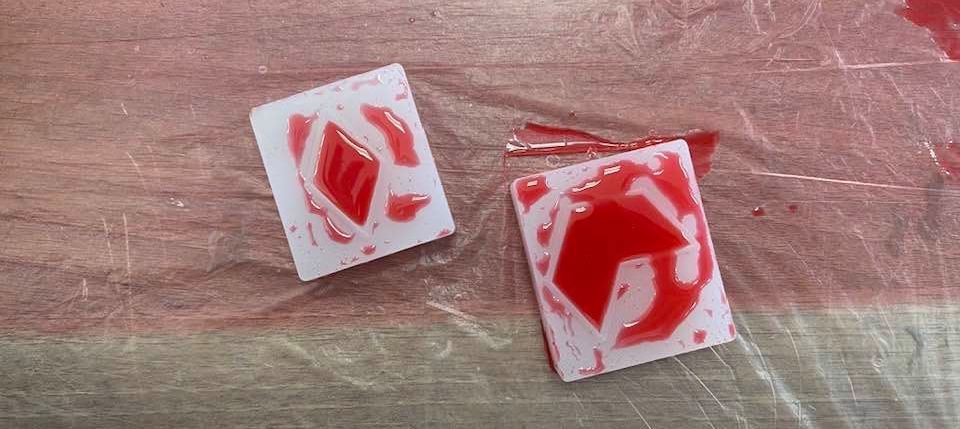
I left this to dry for around a day or two, and then I popped it out of the silicon. Yet, since as aforementioned, the resin pour was messy, the extra edges dried with the design too, so I had to cut them off.
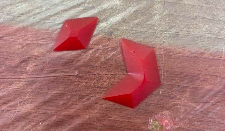
It was so easy to remove it from the mold, and I was honestly pretty impressed by the whole process of molding and casting.
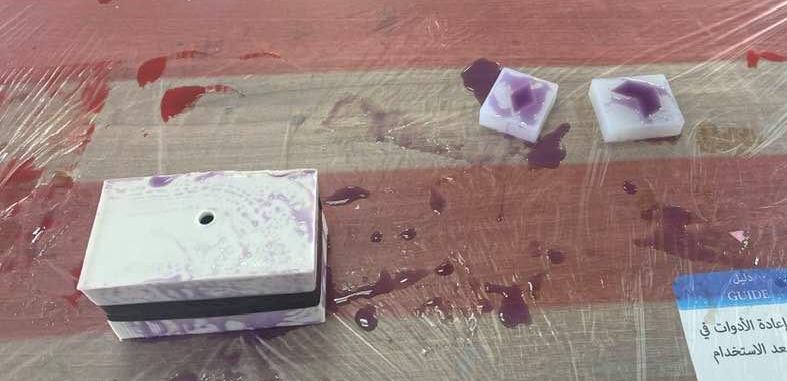
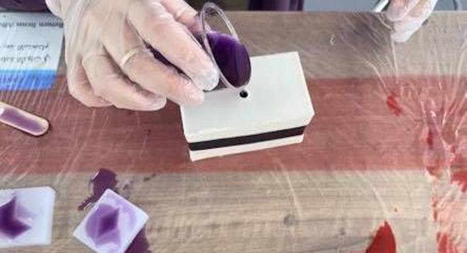
I had alot of extra resin since I messed up the measurments and used the measurments of making the mold rather than the cast, I wanted to try casting with a two-sided mold. So, I grabbed one of the molds done by the previous students of FabAcademy, and I casted a sphere.
I first taped the two pieces together making sure they allign perfectly. Then, through the hole on top, I poured in the resin, and waited for it to dry.
The result was a nice smooth purple sphere - minus some parts.