11. Input devices
This week I started experimenting with input devices that I might use in my final project.
Link to group assignment page.
Individual assignment: measure something: add a sensor to a microcontroller board that you have designed and read it.
During previous weeks, I have made a FabTinyISP and probably 5 ATtiny44 boards. However, for this week, I wanted to use the motion sensors as my input device as I will be using it for my final project.
Sound Module ISD1820
Able to act as both an input and an output device, the sound module ISDI1820 allows you to record and play audio files. This Voice Recorder/Playback module is designed with embedded-Flash memory, which can hold data for up to 100 years and erase/record the life cycle up to 100,000.
The pinout is clearly labelled on the board:

First, I programmed my ATtiny44, following the embedded programming week steps, using this code. I faced many troubles, first I got the rc -1 error which meant I had an issue with connections.

Using the most DIY way, I found that the issue was in the missing RST connection (revert back to electronics design week for the full story). I had a jumper wire to fix that but my jumper wire connecting the missing RST connection fell off. Placing each tong of the tweezers I forged a connection, and the code actually loaded lol!

So, using my solder iron at home, I quickly re-soldered it. But even then I made another mistake, I soldered it to the wrong pin… It took awhile to realize this, but got it fixed, and code was working perfectly.
Update: I just realized that even in the photo the connection I made was a wrong one… But upon doing the correct one the first time, I loaded the code and it worked.

Then I connected the pins of the FTDI on my ATtiny to the respective pins on the ISD1820.
- GND on the ISD1820 to GND on ATtiny44
- VCC on the ISD1820 to VCC on ATtiny44
- PlayL (P-L) on the ISD1820 to PA0 (Arduino pin 0) on ATtiny44
- Record (REC) on the ISD1820 to PA1 (Arduino pin 1) on ATtiny44

Now to test it out, I long-pressed the REC button and started speaking into the microphone. Then, for playback, a long-press for the PLAY-L, and I could hear it playback which was so relieving!
Using the application Audacity, I was able to monitor the recordings and audio files.
Motion sensor
Because I had trouble getting the ATMEGA328P-AU done in time, and I still wanted to experiment with the inputs, I used an Arduino UNO; however, upon completing the board, I will publish the results of the sensors working with my microcontroller.
Using a motion sensor was my first choice since I will be using it in my final project, and I wanted to familiarize myself with it. I found two PIR motion sensors in the lab, but I decided to use the one from Keyestudio since it is smaller, less bulky than the standard one, and has lower power consumption.

This specific PIR sensor detects infrared signals from a moving person or moving animal, and outputs switching signals. It has three pins: VCC, GND, and the signal pin. So, first we connect the input device to the board. I used wires to connect the PIR sensor to the Arduino UNO as follows:

Then, I connected my Arduino UNO to my computer using a USB cable, and I uploaded the code that I got from the WIKI page using Arduino IDE. I launched the serial monitor and started reading the signals being detected.

Soil hygrometer
Because I had trouble getting the ATMEGA328P-AU done in time, and I still wanted to experiment with the inputs, I used an Arduino UNO; however, upon completing the board, I will publish the results of the sensors working with my microcontroller.
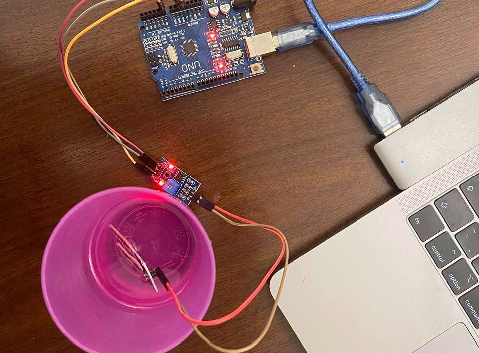
I decided to also try the soil hygrometer because I’ve always loved planting, and this could be a useful sensor in a potential new project concerning planting. Overall, I just wanted to experiment with it. I used the soil moisture sensor by Smart Prototyping.

The board has four pins as labelled on the board; therefore, I connected the board to the Arduino UNO accordingly. However, I didn’t use the Digital Output pin.
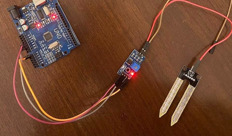
Then like the first sensor, I uploaded the code using Arduino IDE, launched the serial monitor, and started reading the signals.


But, since I didn’t have any soil left at home, I just put the hygrometer into a cup of water lol … it worked fine though.