7. Electronics design
THIS WEEK CHECKLIST
- [✓] Linked to the group assignment page
- [✓] Documented what you have learned in electronics design
- [✓] Explained problems and how you fixed them, if you make a board and it doesn’t work; fix the board (with jumper wires etc) until it does work.
- [✓] Included original design files (Eagle, KiCad, - whatever)
- [✓] Included a ‘hero shot’ of your board
- [✓] Loaded a program and tested if your board works
Group assignment
This time, I work with my groupmates together to use the test equipment in my lab to observe the operation of a microcontroller circuit board (in minimum, check operating voltage on the board with multimeter or voltmeter and use oscilloscope to check noise of operating voltage and interpret a data signal). CLICK HERE for the detailing of group assignment page.
Individual assignment
1. Redraw one of the echo hello-world boards or something equivalent, add (at least) a button and LED (with current-limiting resistor) or equivalent input and output, check the design rules, make it, test it.
Electronics design in Fusion 360
Everything relate to electronics, I have no idea and feel frustrated 🤦🏻♀️. Therefore, I search some tutorials in Youtube and website about making electronic design. I think those materials are easy to understand. I recommend for every beginner in electronic design, just like me.
How to add component: Fusion 360 - Schematic design / Part 1
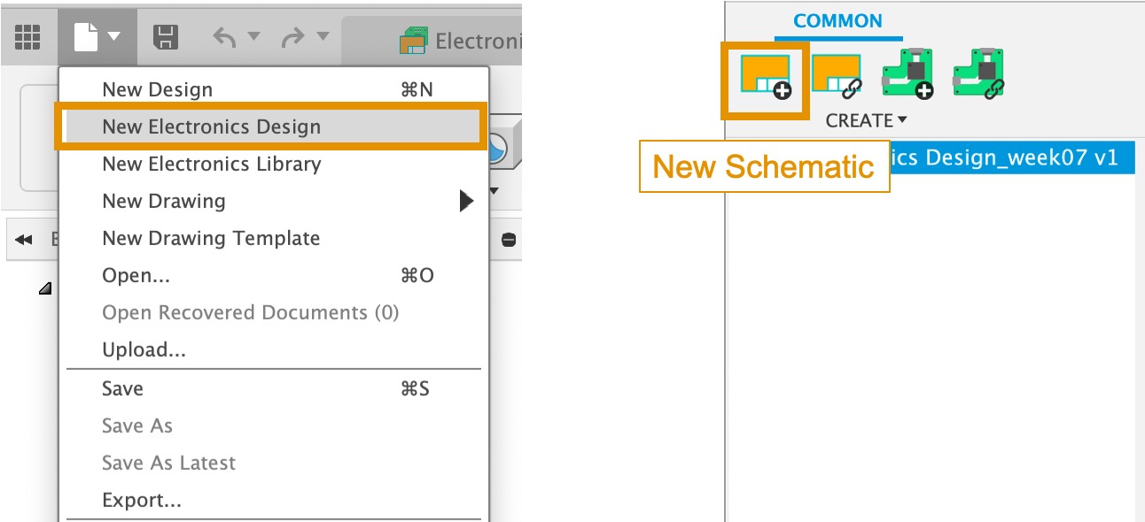
I use Fusion 360 for schematic design. I think Fusion 360 is very powerful, not only able to sketch 3D object, but also design schematic. First, Click New Electronics Design –> New Schematic.
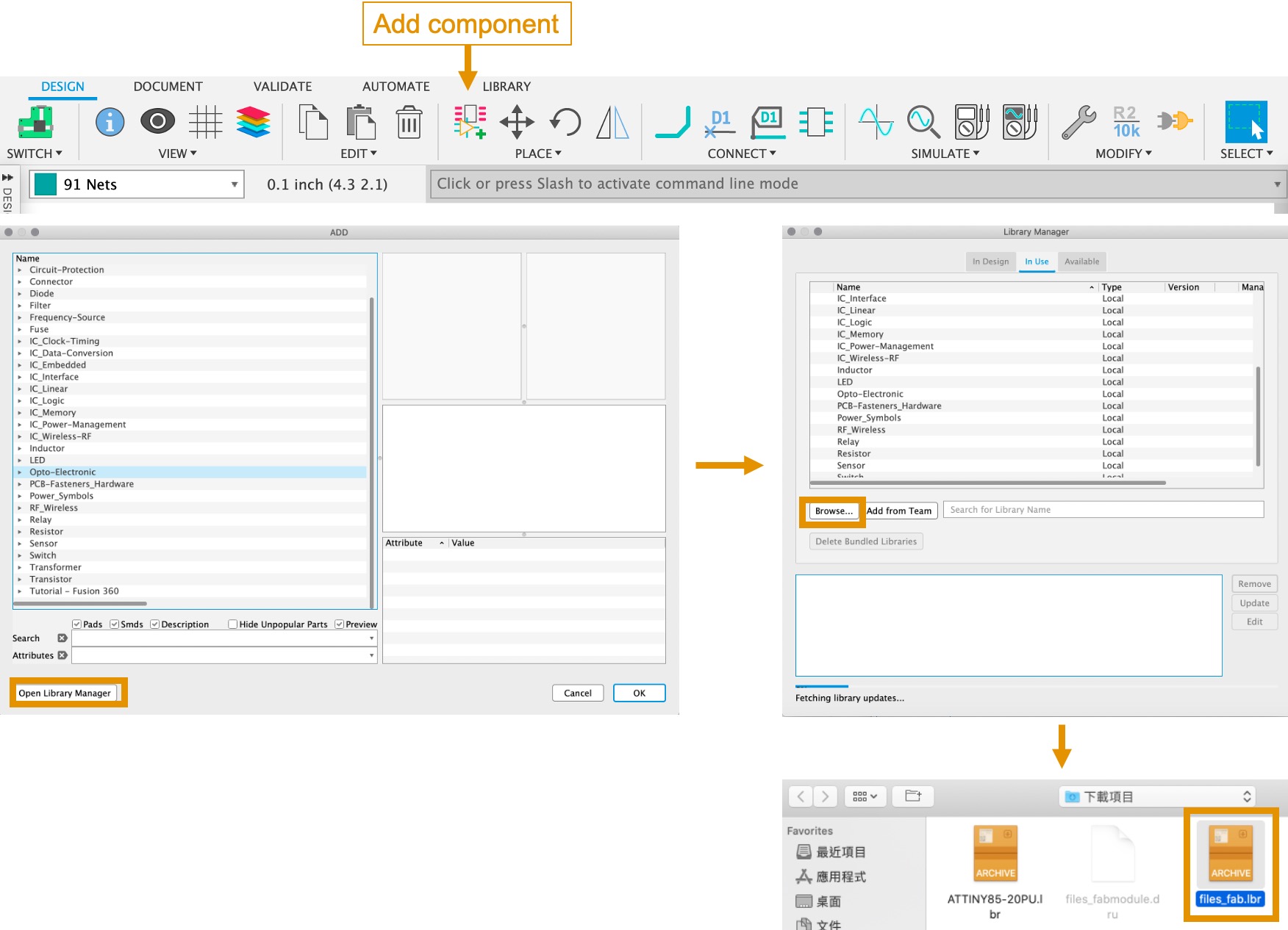
Please download and install the component Libraries fab.lbr,so that you can use when you design the schematic. Here are the step for you to install in your Fusion 360. Click Add component -> Open Library Manger –> Browse –> fab.lbr(you just download the component Libraries).
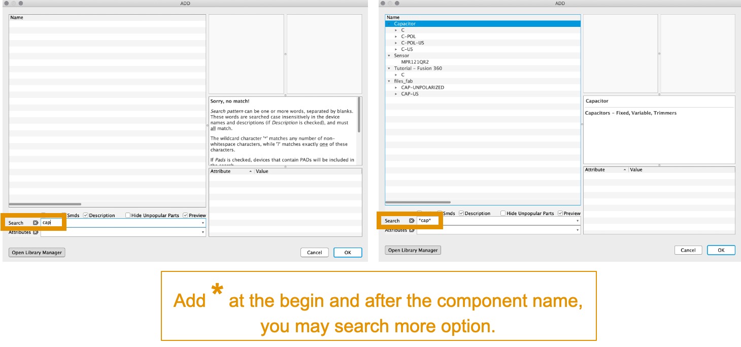
Remember, Add * at the begin and after the component name, you may search more option.
Since I build from an ATtiny85. I cannot find in my Fusion 360 library. Therefore, you may go to SnapEDA to find the symbol and footprint in there. After that, Check “Fusion 360” and download it.
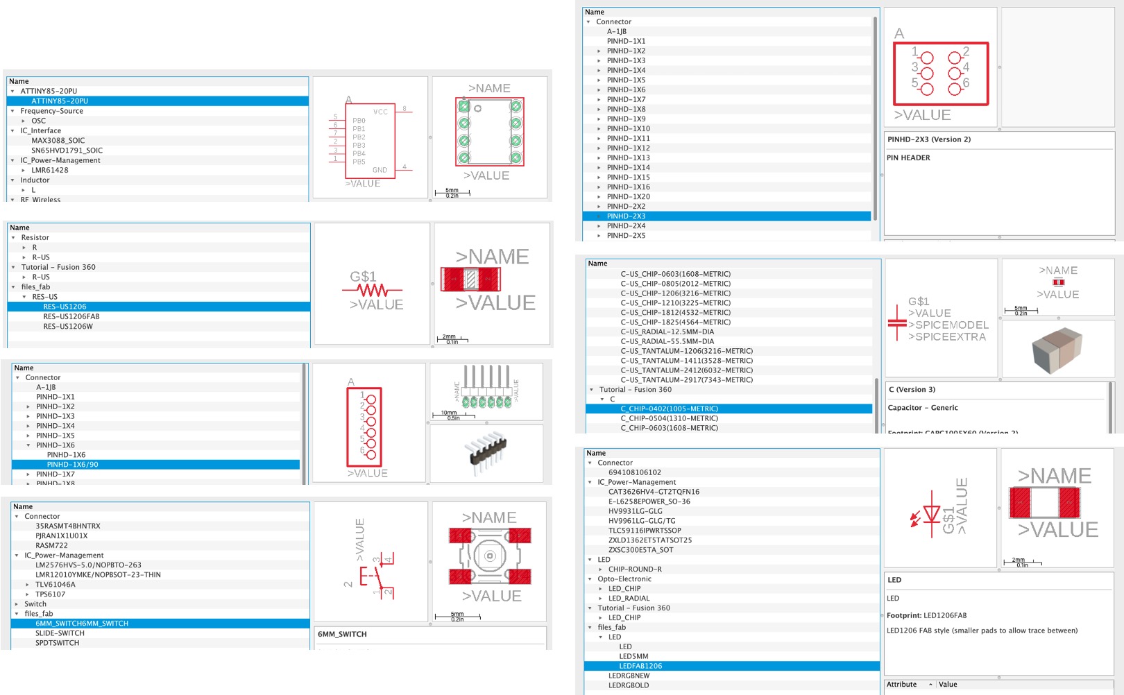
Finally, these are the components import in my schematic.
Since I am not familiar to operate Fusion 360 for designing schematic, so I spend lots of time to understand how to use the below commands:
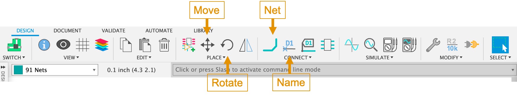
- Move: move the component (Select components, choose move: group, you can move them together)
- Rotate: rotate the component (Select the component hold your Left Click and Press the Roght click)
- Net: connect between components
- Name: add name of components
- Value: add value of components (1k, 10k, 500k for resister and 1uF for capacitor) For changing the value, you sleect the component first and Right Click, choose Properties.
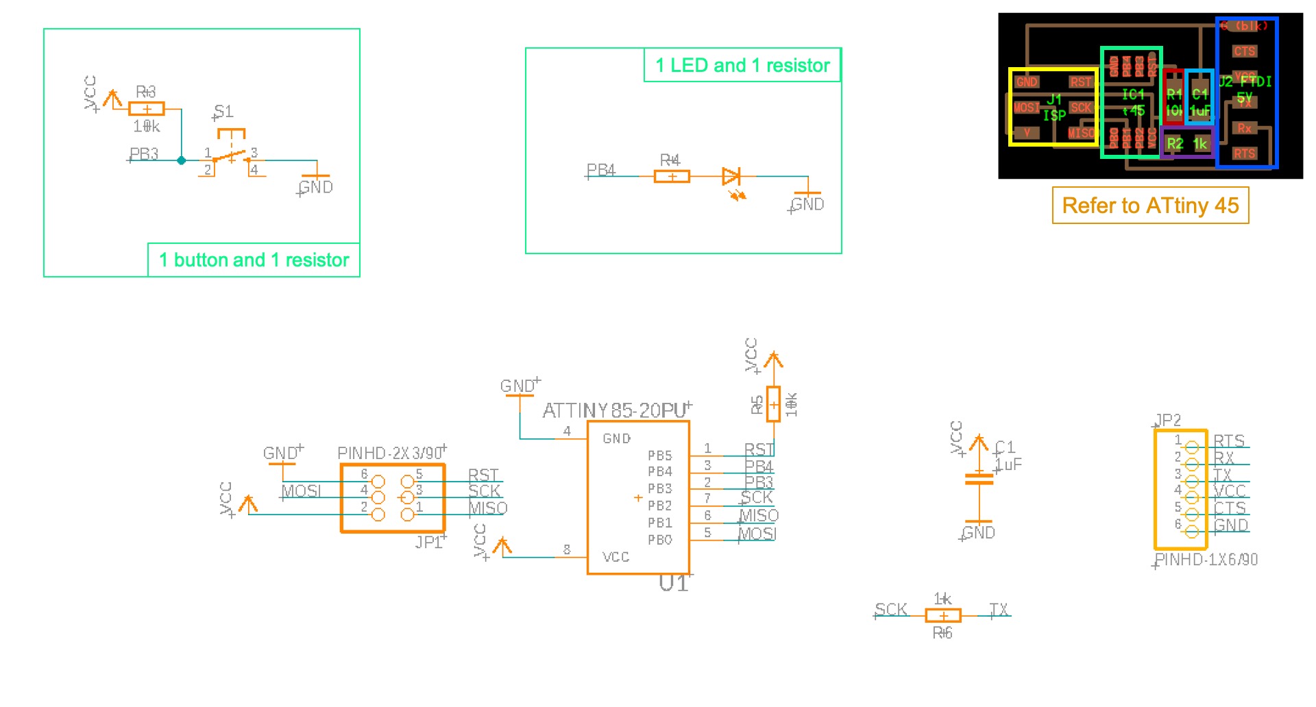
Since I have no idea for designing schematic, so I follow the ATtiny45 schematic as a reference. In additional, adding 1 LED with 1 ressitor and 1 Button with 1 ressitors for designing a new schematic design. Here is the result for adding all the necessary components in my schematic design.
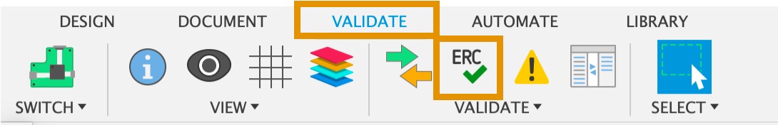
After finishing schematic design, you can go to VALIDATE –> ERC for checking the circuit is correct electrically.
Here is the results for my first draft of schematic design. However, I find that the components that I choose from library is circle pin or size is not correct. It is not the same with my existing components that I use for stuffing. Since I do not realise size and model are important, so I need to change unwanted components.
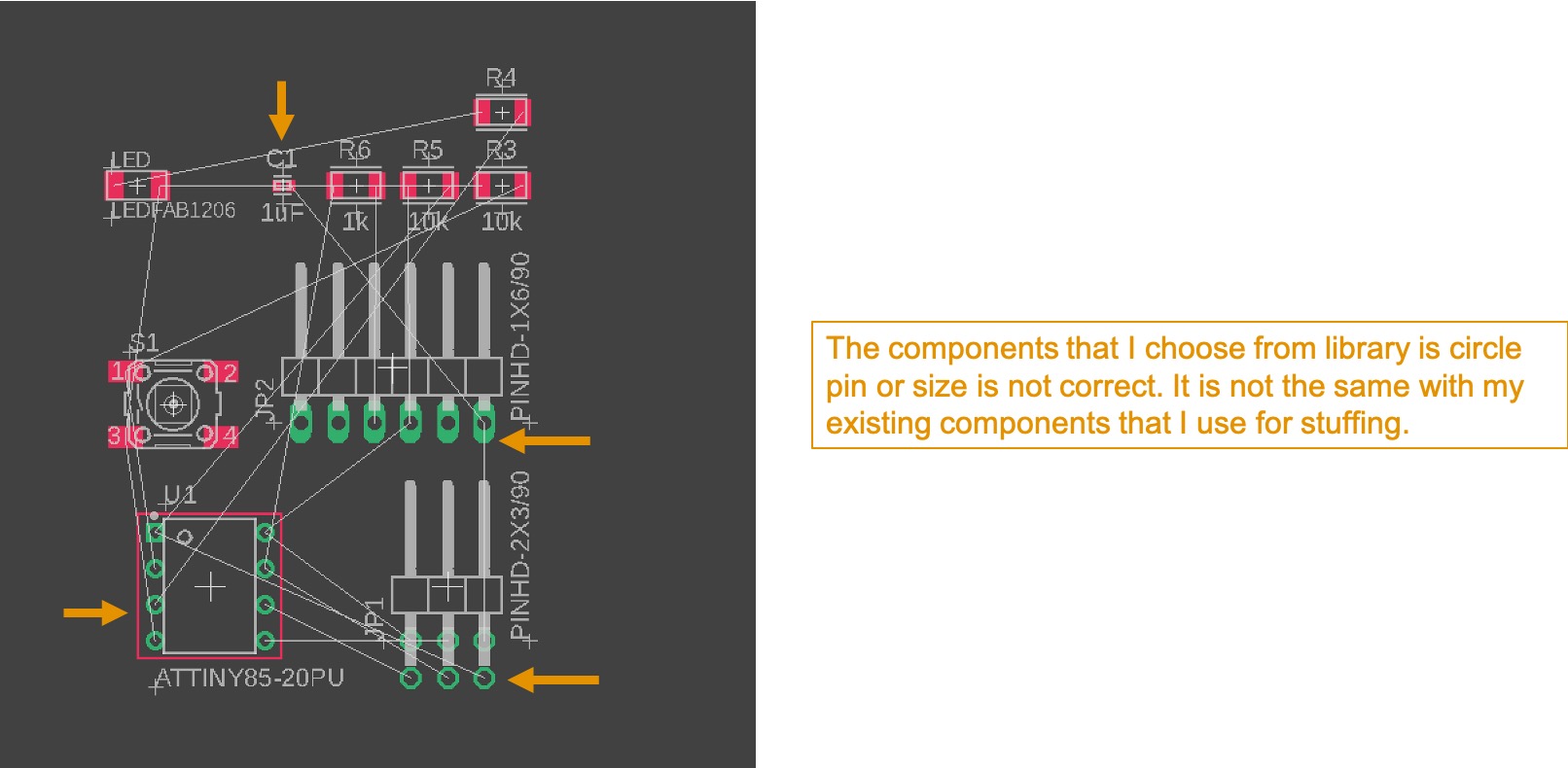
You double click the wrong component, you can choose Replace for replacing the right component in the library. All the connection you set before still keep in the same. However, Fusion 360 show error after you click replace, you only delete the unwanted component and do it again.
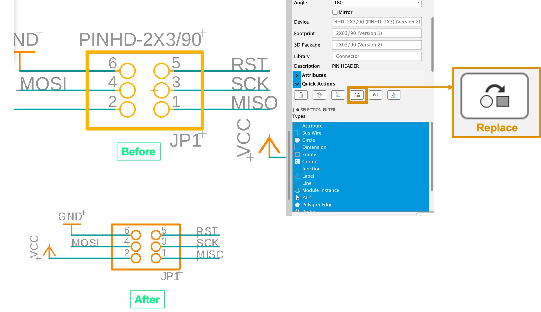
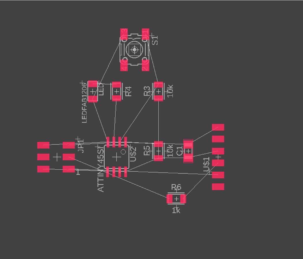
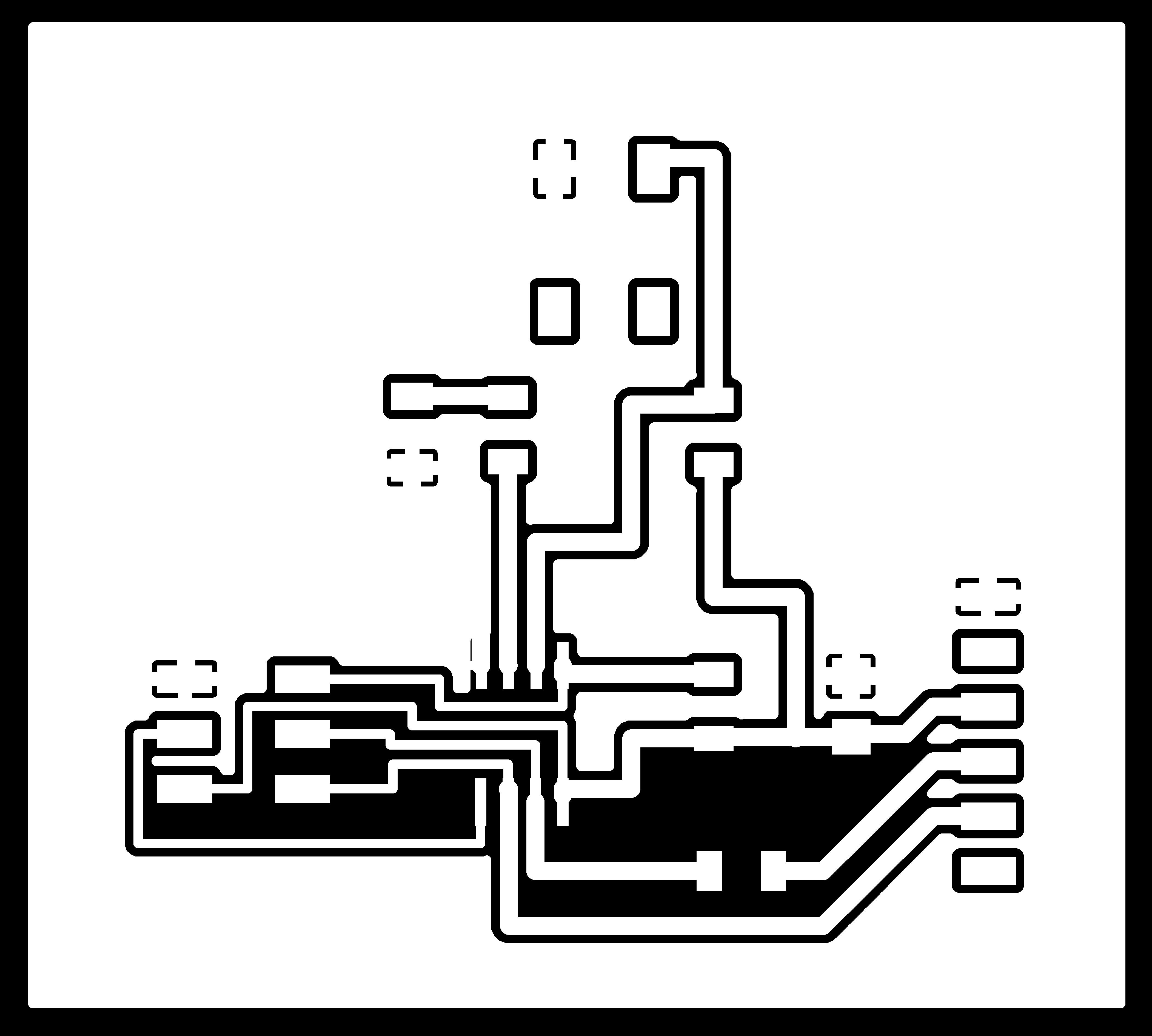
FInally, I replaced all the correct components. Here is the reults in PCB.
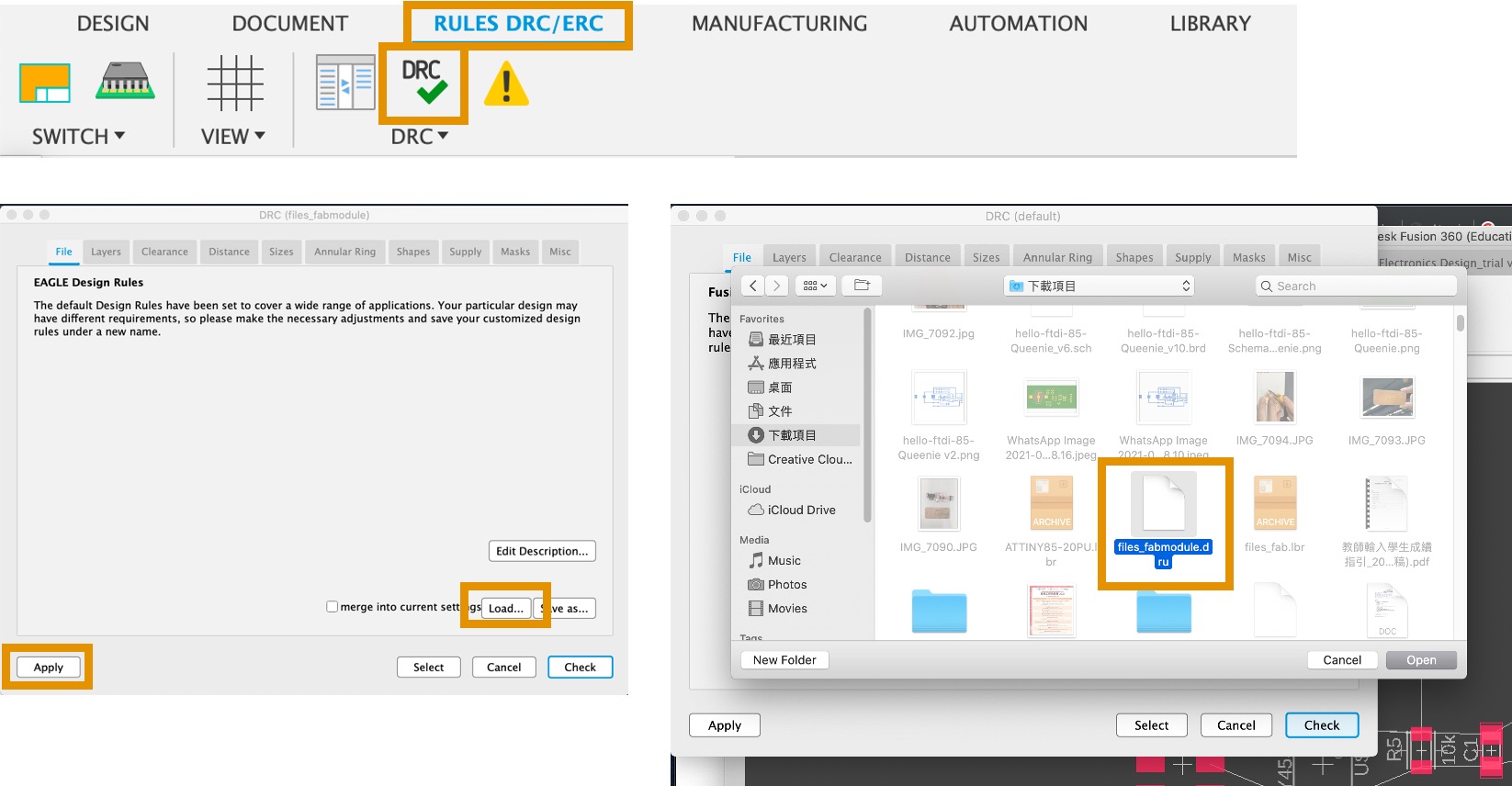
Download the Design Rules Check script and import it into Fusion 360 DRC. Click RULES DRC/ERC –> DRC –> Load –> files_fabmodule.dru –> Apply. Follow the following step.
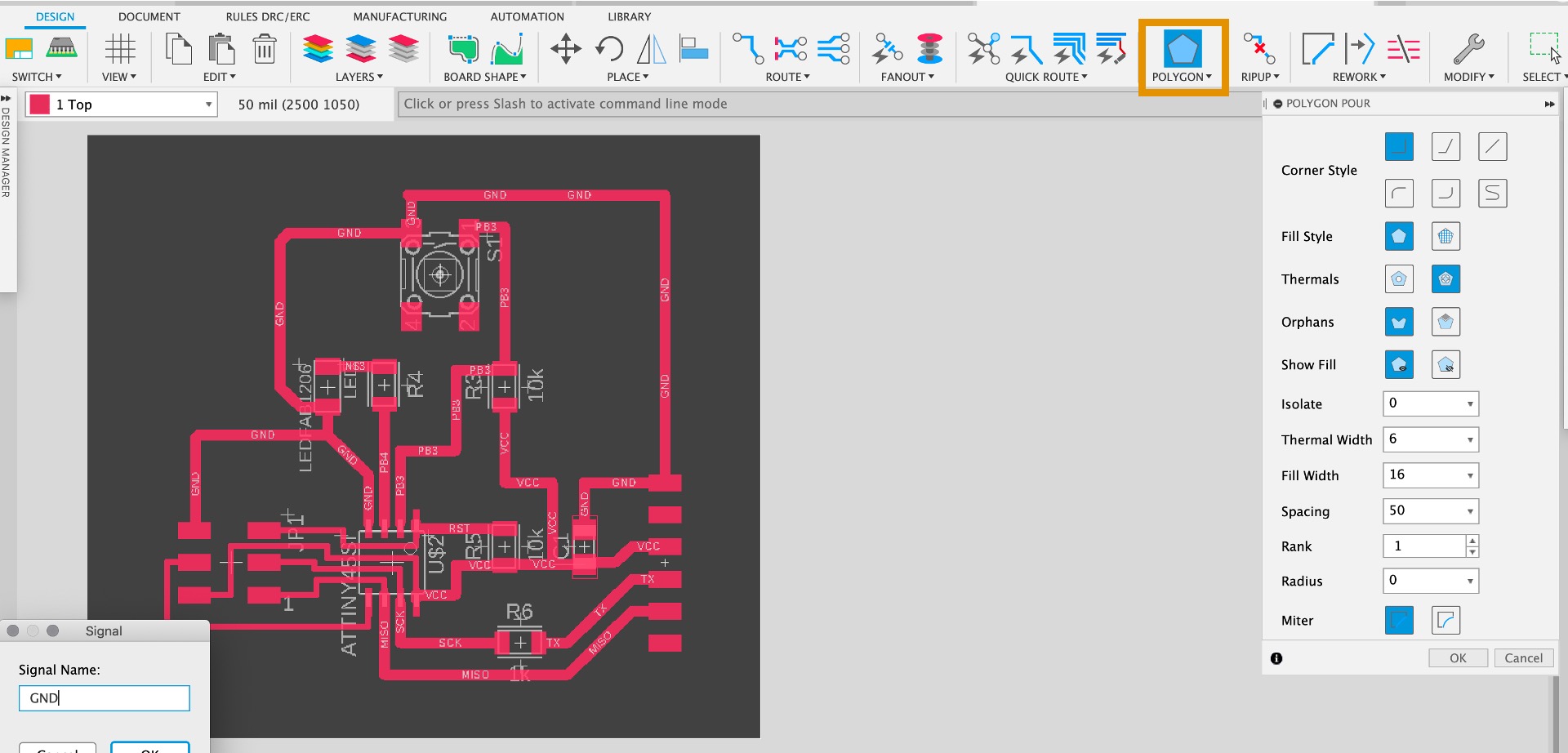
Choose DESIGN –> QUICK ROUTE –> Autoroutor for generating the board pattern. However, the some of the circuit are too close. It may easily happen short circuit when soldering components on the PCB.
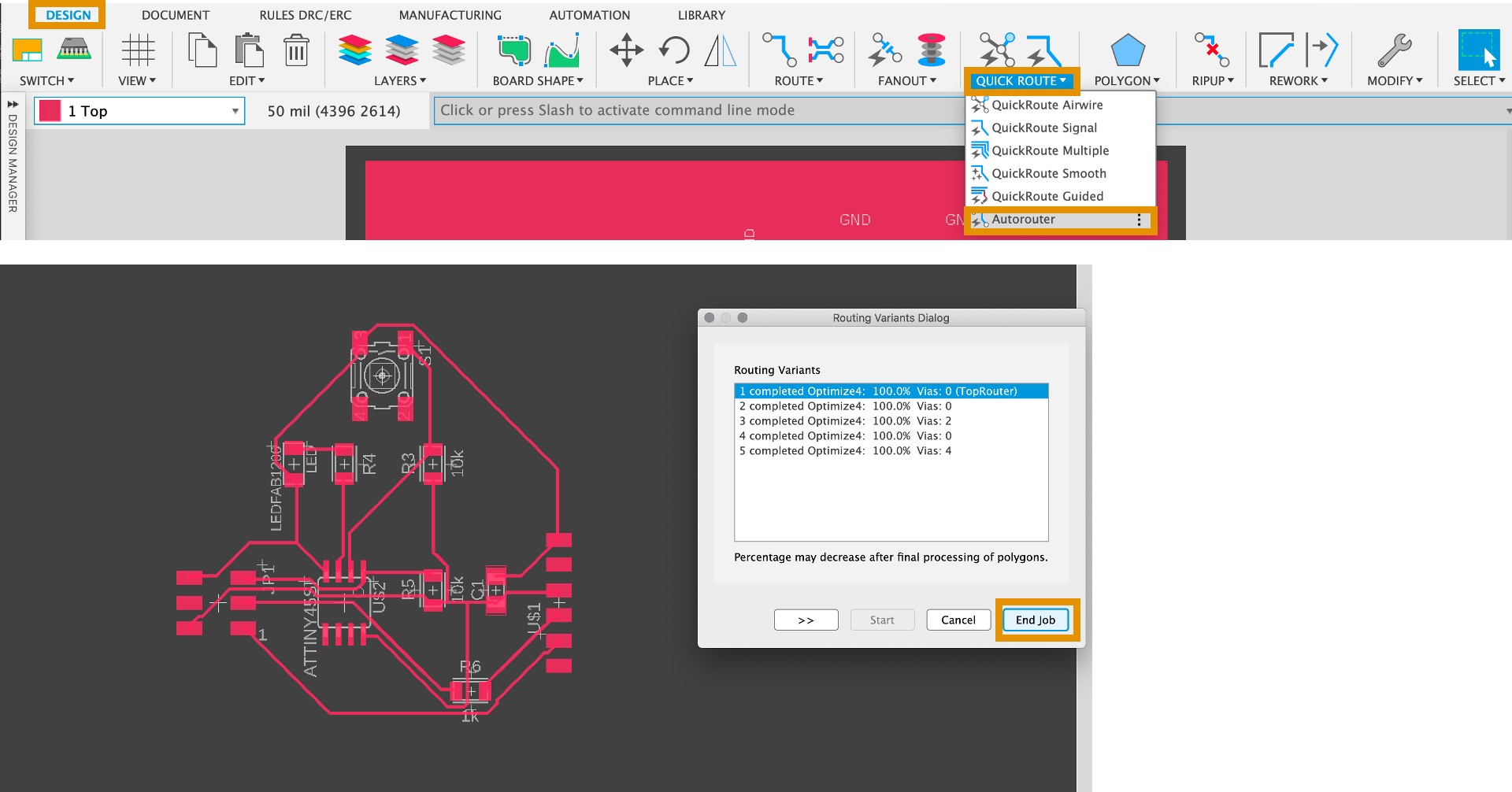
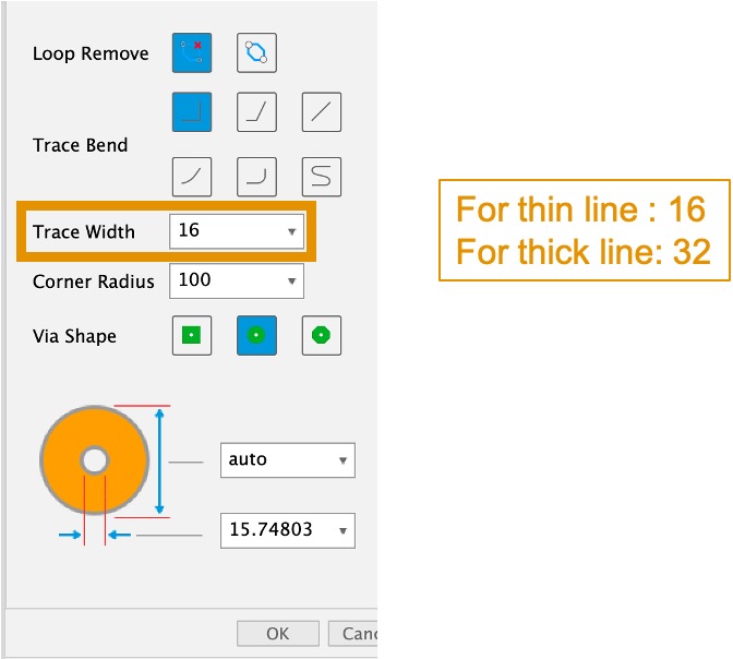
Therefore, I design to route the board pattern by myself. Normally, I set the THICK Line for 32. However, some of the line is too close, I set those as a think line for 16.
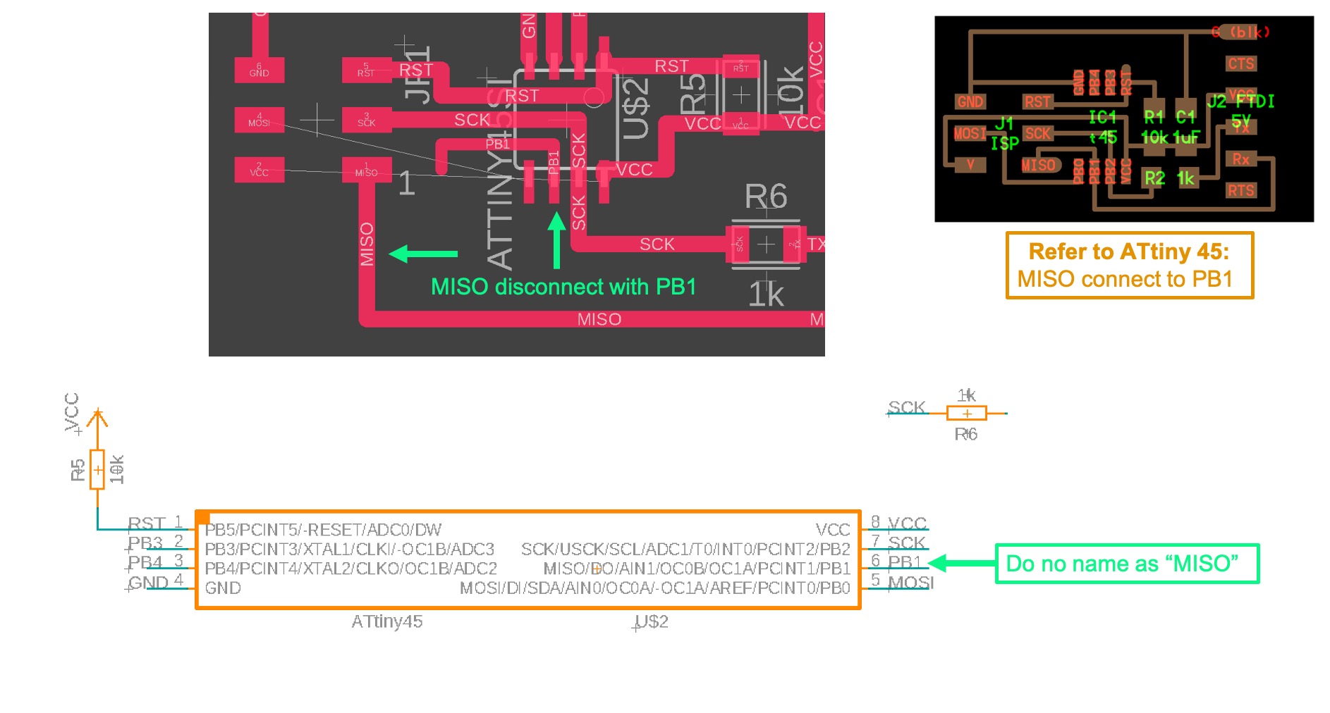
When I route the board pattern, I find some of the circuit did not connect. As you can the reference photo for ATtiny 45. MISO should be connected to PB1. However, I find MISO do not connect with PB1, so I check back to schematic. I find pin 6 do not name in MISO, still name in PB1. Therefore, I name pin 6 in MISO. Connection is back.
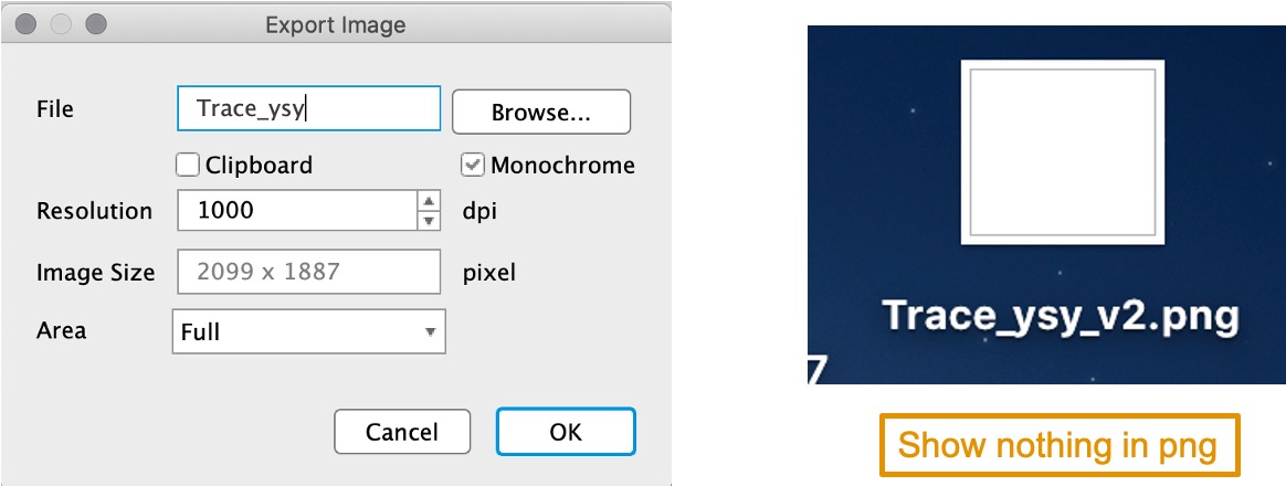
It has a problem in Fusion 360 to export the png file. Even I tick for Monochrome , set 1000 dpi, full area. Finally, Fusion export the wrong file.
Production of PCB
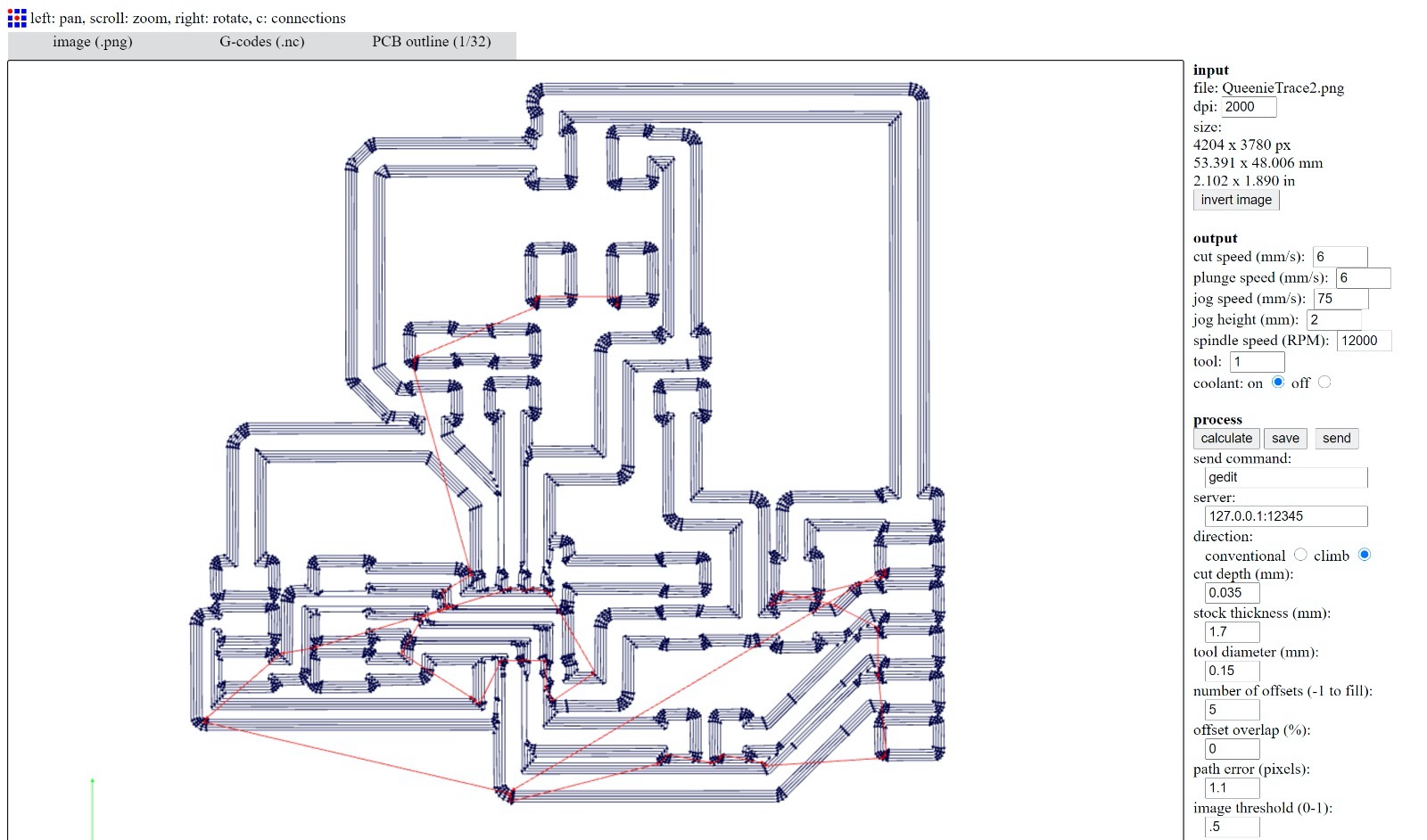
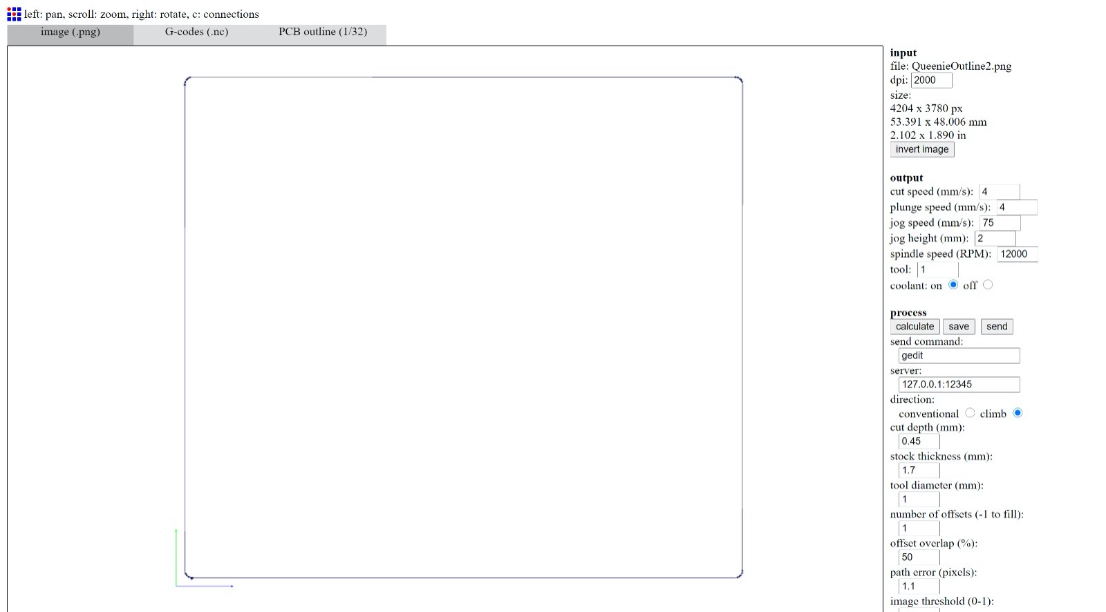
I use Fab Modules for generating the G-code for our CNC (Roland Modela Pro MDX-500).
After milling, I use vacuum cleaner for cleaning. As you can see the right photo in green circle, these part cannot be trace though in milling.
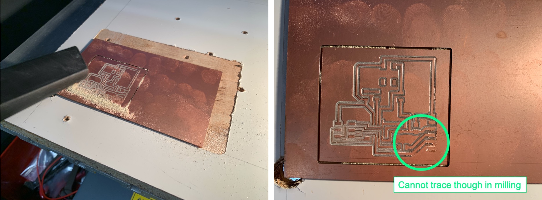
I use multimeter to test for continuity in green circle. The multimeter shows 0.1Ω. It mean these part cannot be trace though in milling.
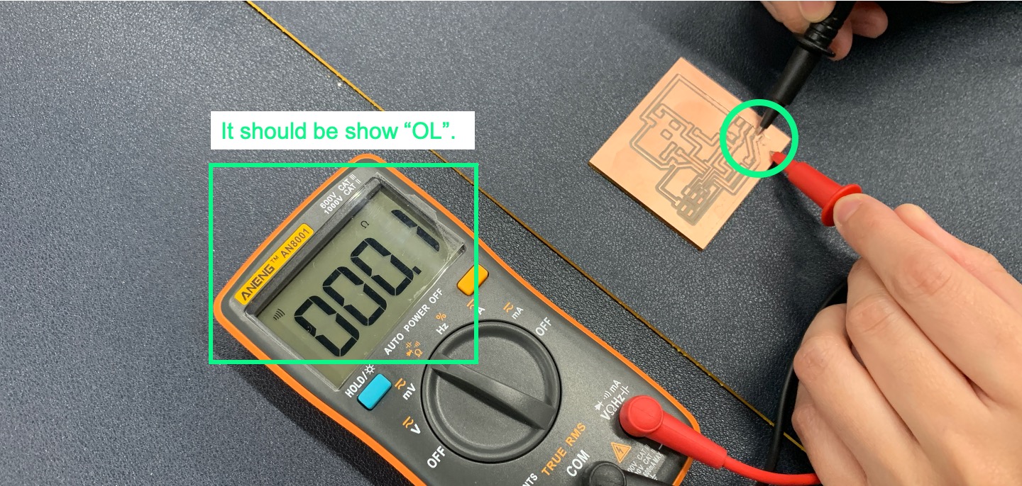
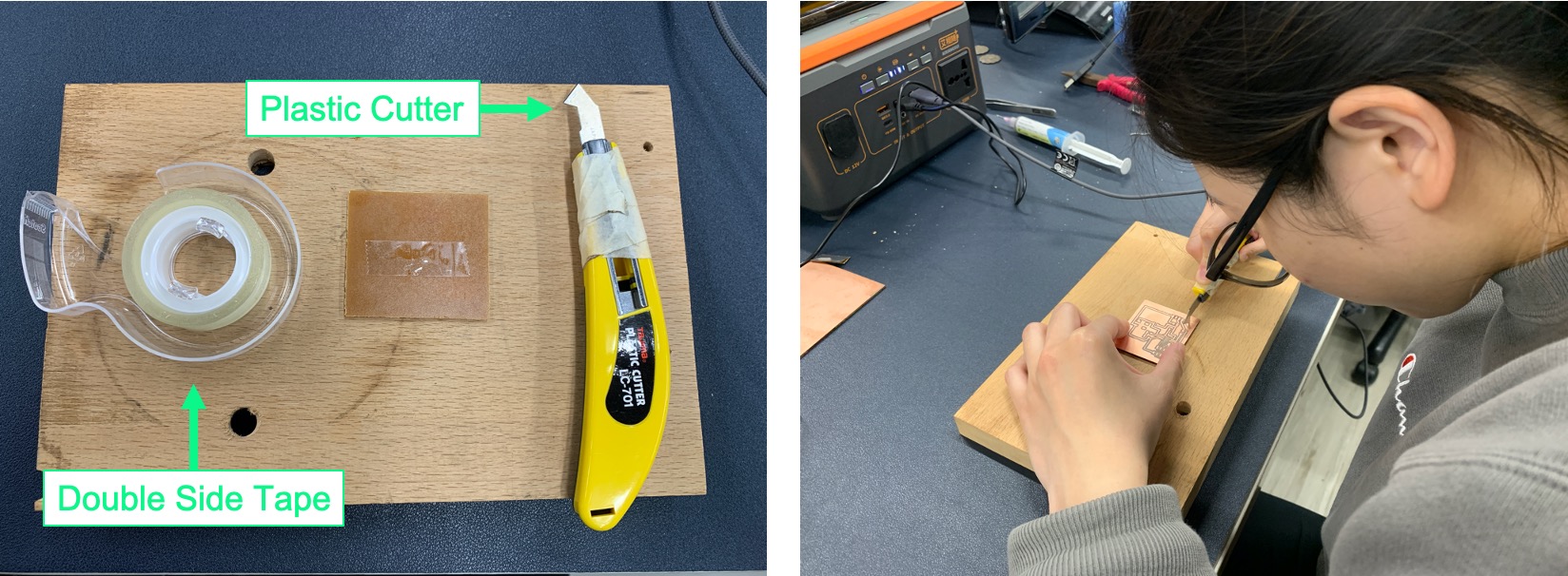
I use Plastic Cutter for scraping. FOR SAFETY, please use Double Side Tape for stable the position before you scrape.
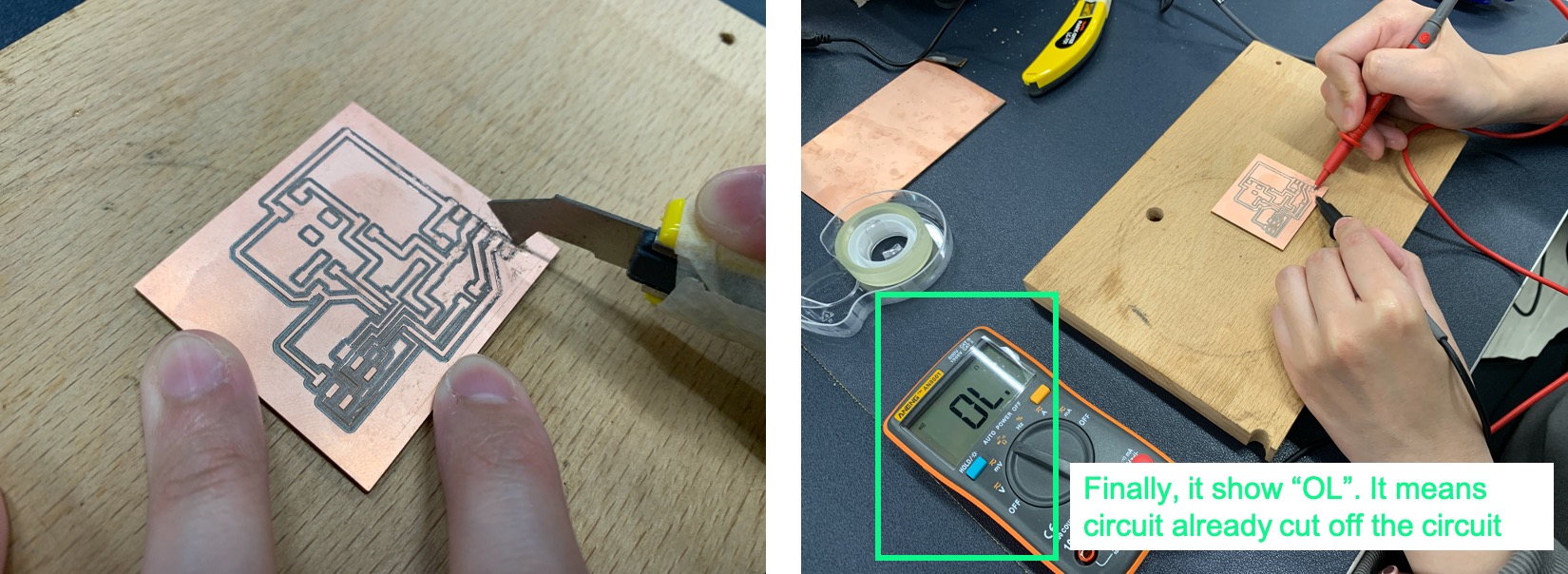
After scraping by Plastic Cutter, multimeter shows OL. It means that part already be fully seperate and no circuit.
Soldering
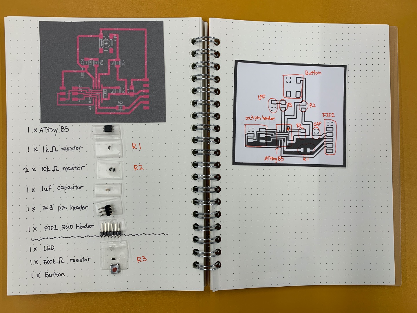
Before, soldering components in the PCB. Collect and paste all components in my notebook. Also, I need to identifty all components position. It makes sure the direction and position of the components are correct. I may not feel confused when I am soldering.
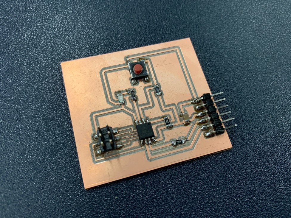
Basic on the soldering experience in week05. After finishing soldering in every point, I will use multimeter to test the voltage, short circuit situation or resistor value is that correct. If not, I must be fixed immediately. It is hard to test for finishing all soldering part. Here is the final board with soldering.
Loading program and testing PCB
Here is the sorce code for my testing.
int buttonState = 0;
// the setup function runs once when you press reset or power the board
void setup() {

  // initialize digital pin LED_BUILTIN as an output.
  pinMode(3, INPUT);
  pinMode(4, OUTPUT);
}

// the loop function runs over and over again forever
void loop() {
   // read the state of the pushbutton value:
  buttonState = digitalRead(3);
  if (buttonState == HIGH) {
  digitalWrite(4, LOW);   // turn the LED on (HIGH is the voltage level)
  delay(200);                       // wait for a second

  digitalWrite(4, HIGH);   // turn the LED on (HIGH is the voltage level)
  delay(200);                       // wait for a second
  } else {
  // turn LED ON:
    digitalWrite(4, HIGH);
     }

}
File Download
Fusion360 Schematic Design
Fusion360 PCB Design
PCB Milling:
PCB_Trace
PCB_Outline