13. Output devices
THIS WEEK CHECKLIST:
- [✓] Linked to the group assignment page
- [✓] Documented how you determined power consumption of an output device with your group
- [✓] Documented what you learned from interfacing output device(s) to microcontroller and controlling the device(s)
- [✓] Described your design and fabrication process or linked to previous examples.
- [✓] Explained the programming process/es you used.
- [✓] Outlined problems and how you fixed them
- [✓] Included original design files and code
- [✓] Included a ‘hero shot/video’ of your board
Group assignment
This time, I work with my groupmates together to measure the power consumption of an output device. CLICK HERE for the detailing of group assignment page.
Individual assignment
- Demonstrate workflows used in controlling an output device(s) with MCU board you have designed
In week07, I made a board from an ATtiny85. Also, I read the data sheet to understand the Pinout Diagram of ATtiny85 in week09. Therefore, I used this board for adding potentiometer (input device) in week11. Finally, I try to control the servo motor with the same board that I design in week11.
Since my final project is about the ALUMINIUM CAN RECYCLING BIN. One of the output device is using Electronic Speed Control (ESC) to control brushed DC motor for crushing cans. Since ESC and servo motor controlled by PWM, so I decide to control the seveo motor by ATtiny 85 board that I design in week11 first, as a test. If I am able to control the servo motor by PWM, I means that it is able to use to ECS to control brushed DC motor for crushing cans.
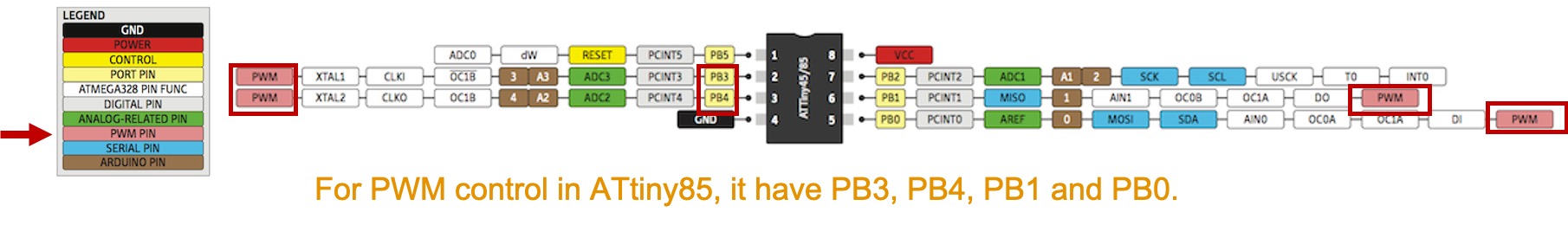
For PWM control in ATtiny85, it have PB3, PB4, PB1 and PB0.
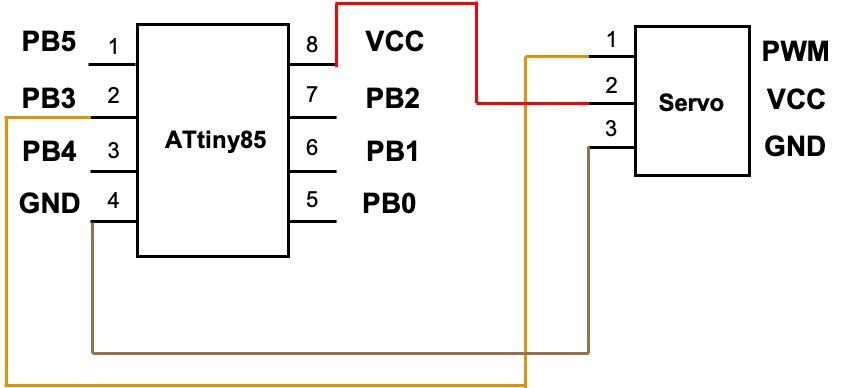
In this time, I use PB3 as a PWM control seveo motor. Here is the electronic circuit between ATtiny85 to servo motor (SG90).
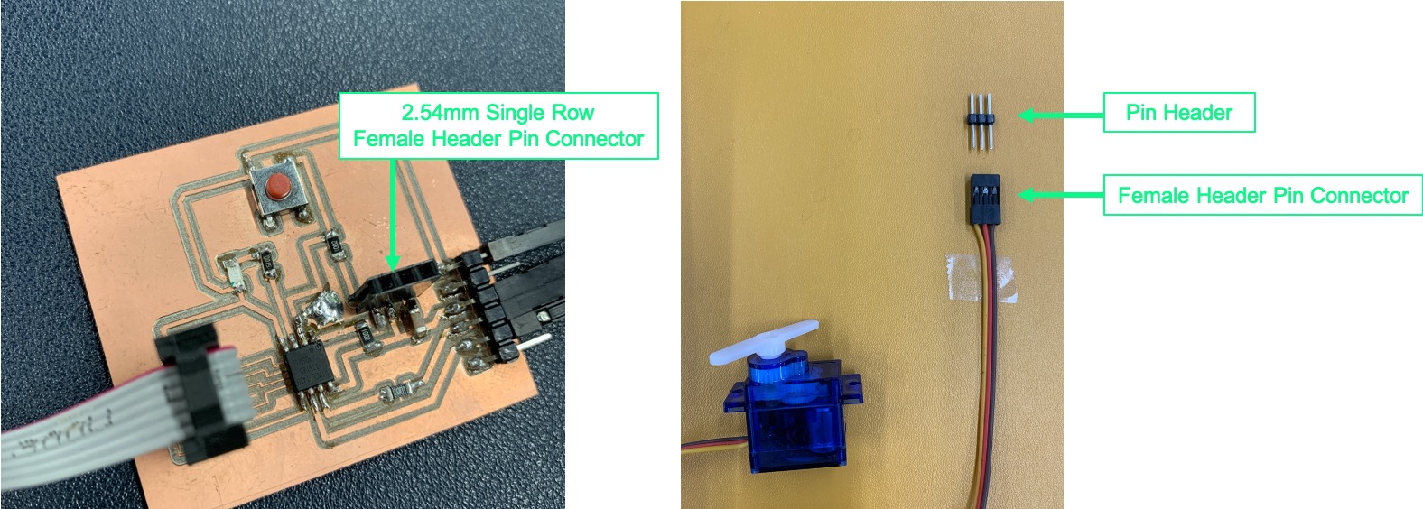
To connnect with 2.54mm Single Row Female Header Pin Connector in my board and Female Header Pin Connector of servo motor, adding Pin Header for connecting.
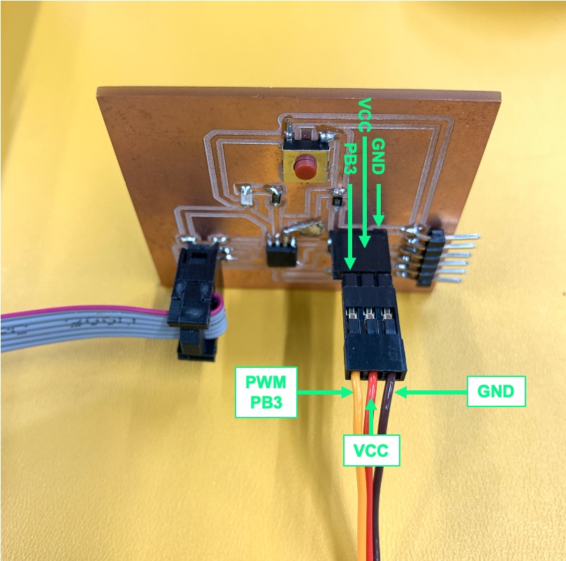
This is how I connect with my board (ATtiny85) and servo motor.
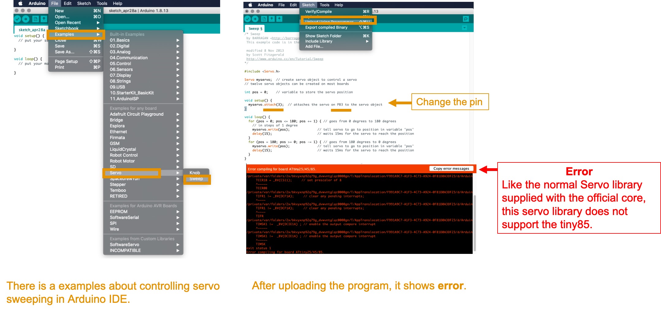
There is a example about controlling servo sweeping in Arduino IDE. However, I change the correct pin in my board. After, I uploaded the program. It shows error compiling board ATtiny85. After I search on the internet, there is a website is talking about Servo library doesn’t compile on ATtiny85. The result is Like the normal Servo library supplied with the official core, this servo library does not support the tiny85/45/25 or tiny861/461/261.
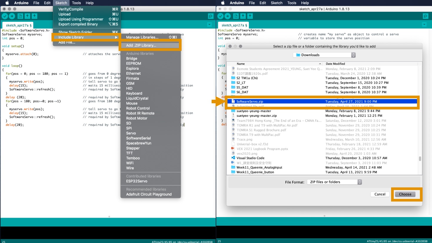
I try to use software servo library. You may CLICK HERE for dowloading SoftwareServo zip file. Go to Sketch –> Include Library –> Add .ZIP Libraries and choose the SoftwareServo.zip.
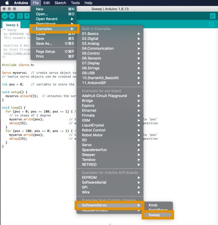
After adding the software servo library, I use the sample code from there. Go to Examples –> SoftwareServo –> Sweep.
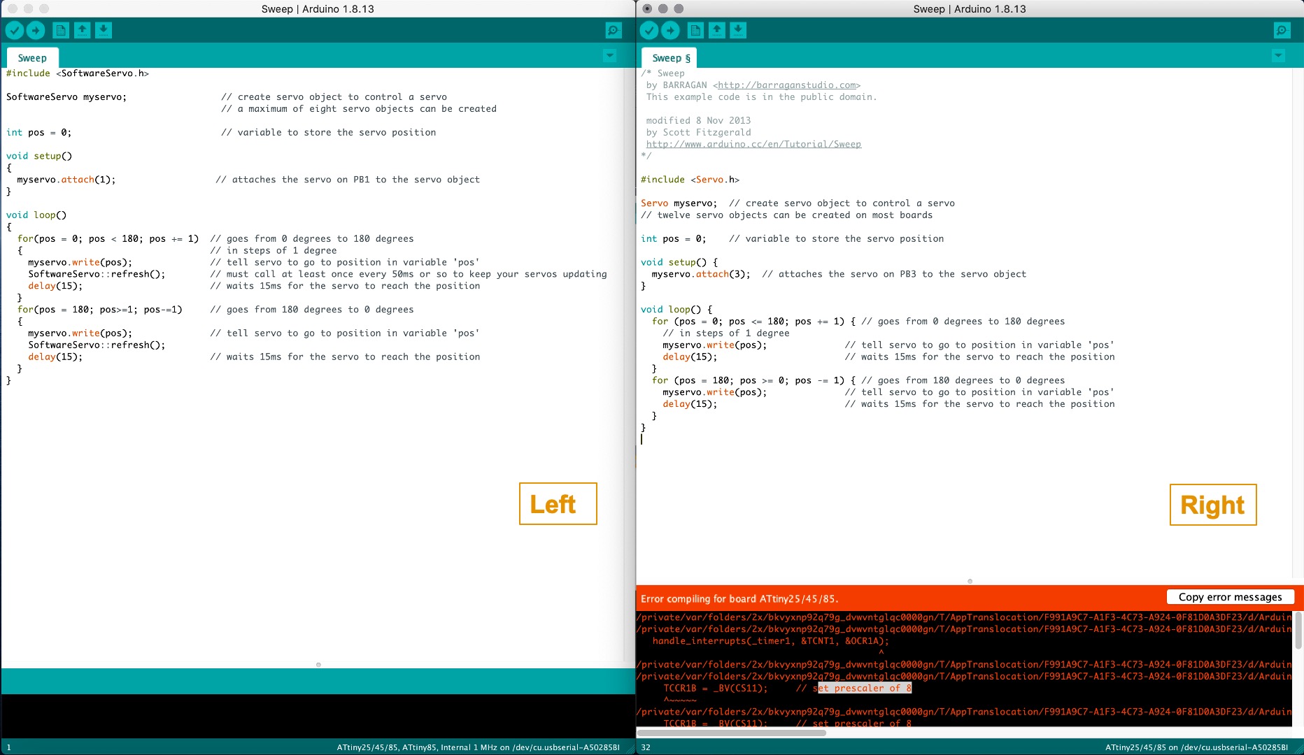
Left Photo: After adding the Software servo header file , it may support ATtiny85
Right Photo: Official servo header file core do not support ATtiny85
Here is the testing results.
This is the code for sweeping program from AVRFREAKS. There are the functions that available in this library.
- attach() - Attach the Servo variable to a pin.
- write() – Writes a value in degrees to the servo, controlling the shaft accordingly.
In this time, I changed myservo.attach(0) to myservo.attach(3). Here is the sorce code for my testing.
#include <SoftwareServo.h>
SoftwareServo myservo;                      // creates name “my servo” as object to control a servo
int pos = 0;                                // variable to store the servo position

void setup()
{
  myservo.attach(3);                        // attaches the servo on **PB3** to the servo object
}

void loop()
{
  for(pos = 0; pos <= 180; pos += 1)        // goes from 0 degrees to 180 degrees
  {                                         // in steps of 1 degree
    myservo.write(pos);                     // tell servo to go to position in variable 'pos'
    delay(15);                              // waits 15 milliseconds for the servo to reach the position
    SoftwareServo::refresh();               // required by SoftwareServo Library to sweep correctly
  }
  delay (20);                               // required by SoftwareServo Library to sweep correctly
  for(pos = 180; pos>=0; pos-=1)            // goes from 180 degrees to 0 degrees
  {
    myservo.write(pos);                     // tell servo to go to position in variable 'pos'
    delay(15);                              // waits 15 milliseconds for the servo to reach the position
    SoftwareServo::refresh();               // required by SoftwareServo Library to sweep correctly
  }
  delay(20);                                // required by SoftwareServo Library to sweep correctly
}
When a servo is attached to a pin a PWM servo control signal will start being generated on that pin. By default it will command the servo to move to its middle position. You can command the servo to move by calling the write() function and passing in a number between 0 and 180. This number represents rotational position in degrees.