11. Input devices
THIS WEEK CHECKLIST:
- [✓] Linked to the group assignment page
- [✓] Documented what you learned from interfacing an input device(s) to microcontroller and how the physical property relates to the measured results
- [✓] Documented your design and fabrication process or linked to previous examples.
- [✓] Explained the programming process/es you used
- [✓] Explained problems and how you fixed them
- [✓] Included original design files and source code
- [✓] Included a ‘hero shot/video’ of your board
Group assignment
This time, I work with my groupmates together to probe an input device(s)’s analog and digital signals. CLICK HERE for the detailing of group assignment page.
Individual assignment
Measure something: add a sensor to a microcontroller board that you have designed and read it.
In week07, I made a board from an ATtiny85. Also, I read the data sheet to understand the Pinout Diagram of ATtiny85 in week09.
Modifty the board design
For this week, I keep using ATtiny85 for adding a sensor. However, the number of pin of ATtiny85 is little. Therefore, I do not think that making a new board by ATtiny85 is not a good idea. Finally, I decide to use the board that I made in week07.
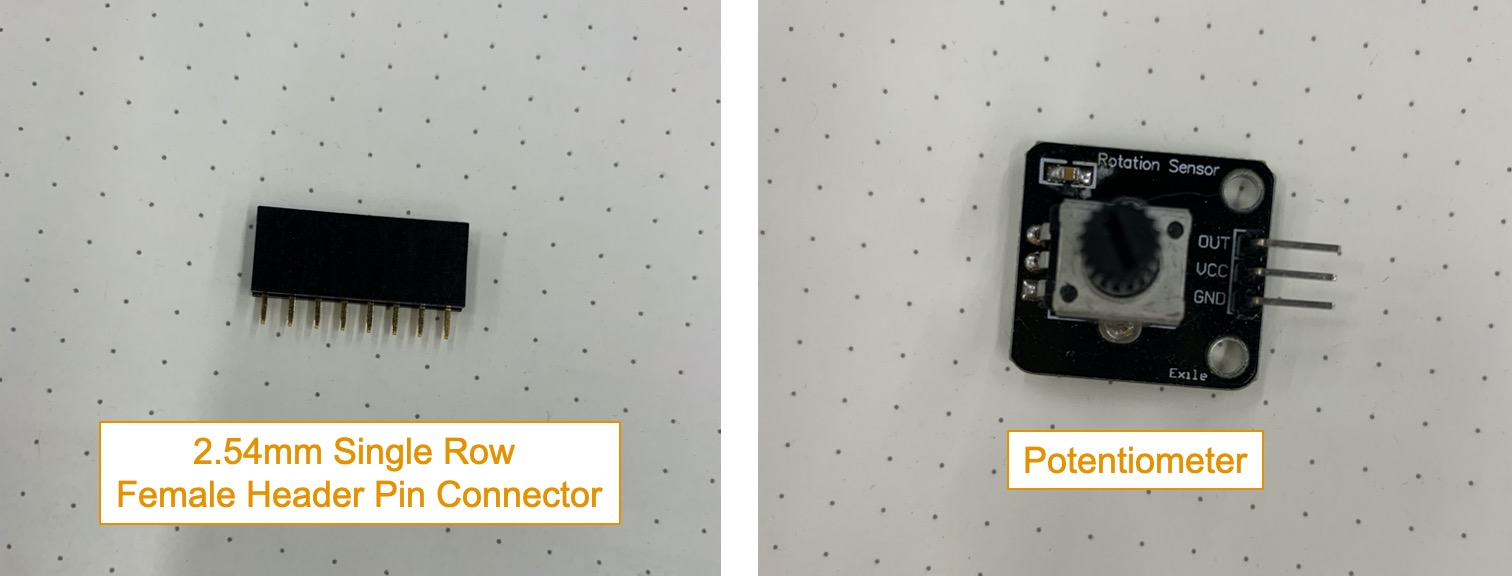
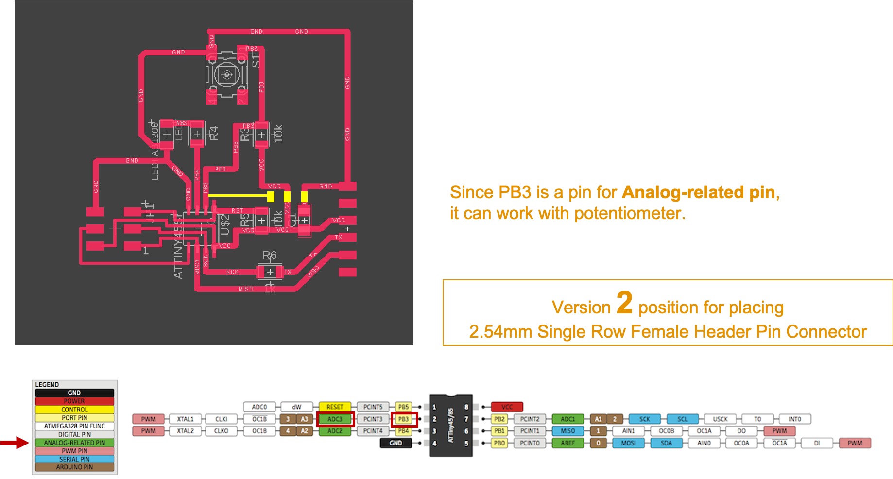
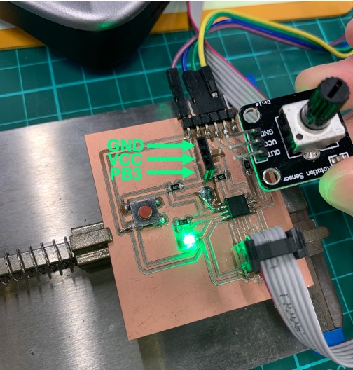
For minimum modifty in the board design, I add 2.54mm Single Row Female Header Pin Connector for inserting the input device for my testing. I decide to use potentiometer as an analog input device. It is a passive device that provides an adjustable electrical resistance. Also, it is a convenient way of allowing user input to a running Arduino program.
Be careful the pin of different potentiometer. Different potentiometer may have different pin layout. You need to check with multimeter to define which pin is VCC, GND and Signal.
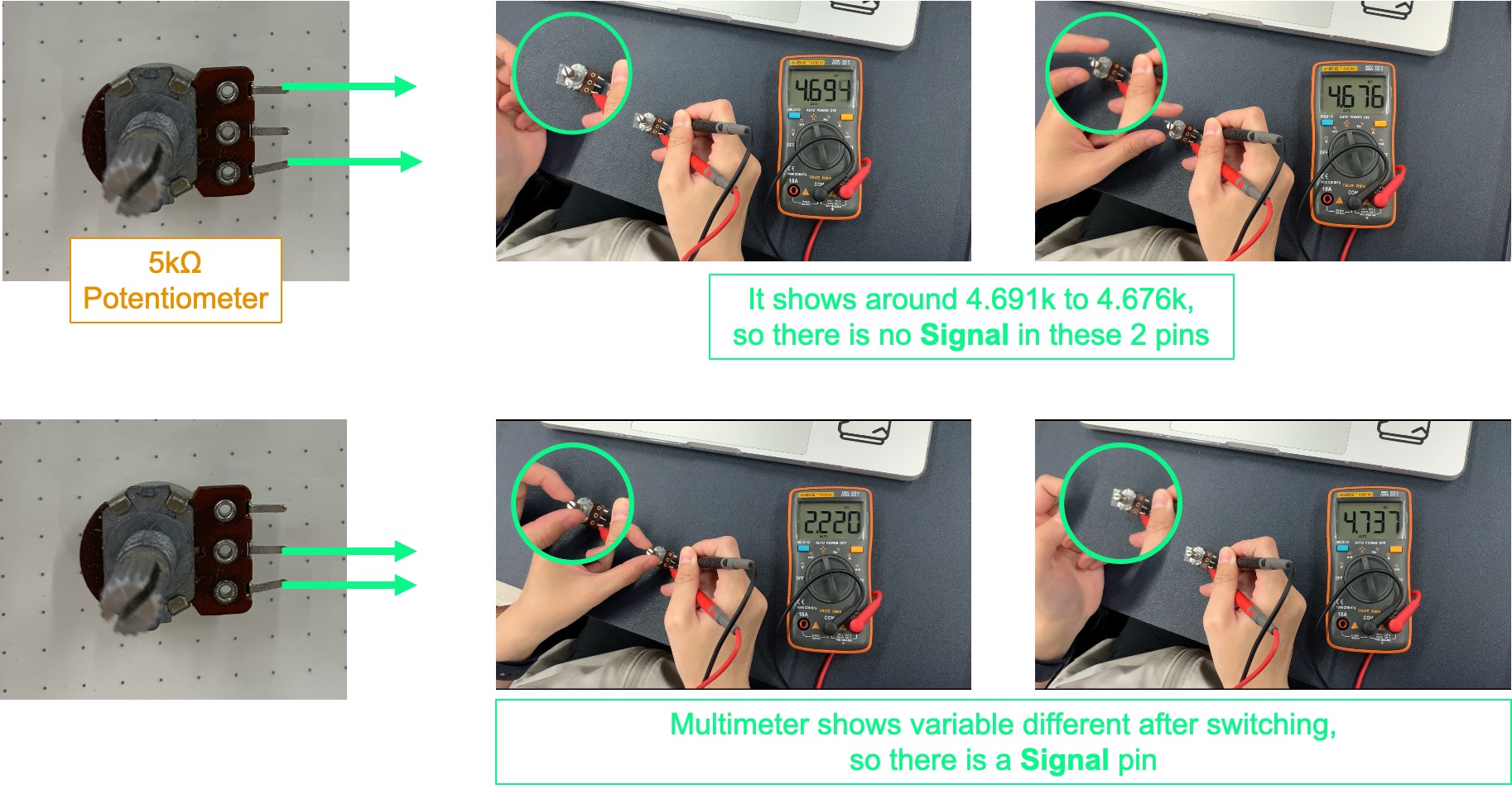
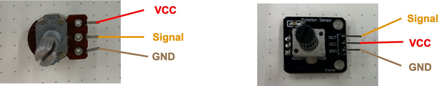
Since the final product of the potentiometer may use in different board. Especailly, using in our own design board. Please define the pin first before you use. This is the result of my testing.
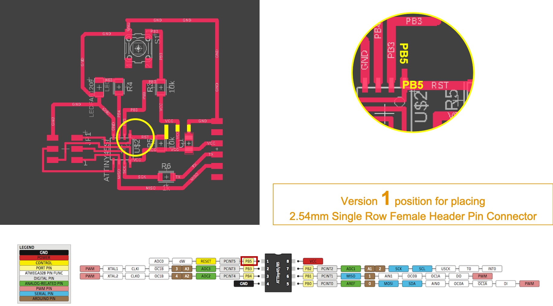
For version 1, I try to use PB5 for placing 2.54mm Single Row Female Header Pin Connector. However, after I check with the pinout diagram, PB5 can not be used because there are no analog-related pin. It is not fit with potentiometer.
For version 2, I check with the pinout diagram, PB3 can ne used for analog-related pin. Therefore, I can use PB3 for placing 2.54mm Single Row Female Header Pin Connector.
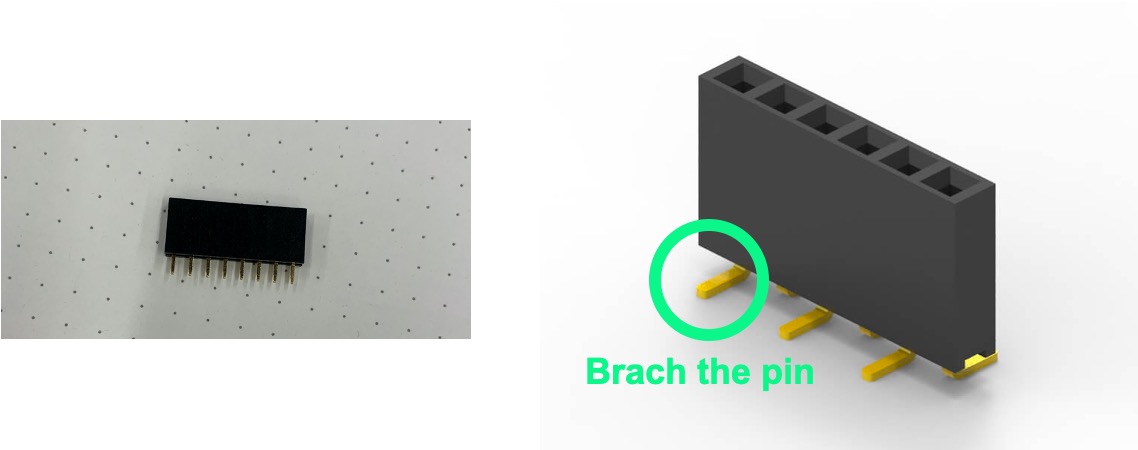
Baching the pin for making PB3 connecting with VCC and GND, so that I can inserting the potentiometer.
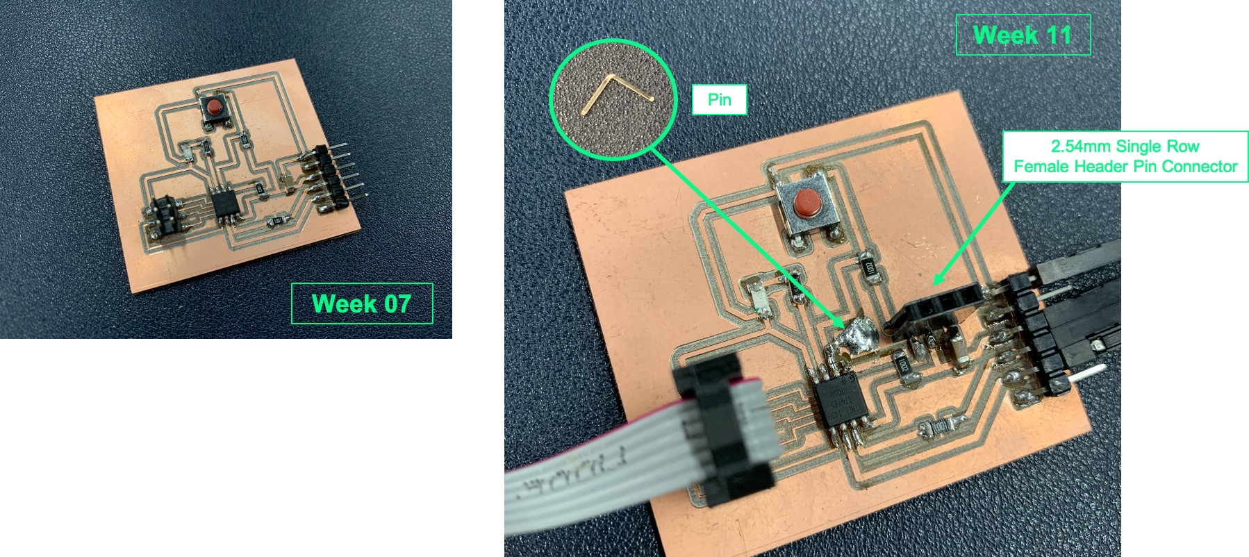
Left: The board I made in week 07.
Right: Soldering 2.54mm Single Row **Female Header Pin Connector and soldering a pin for increasing the conductive and stablize between PB3, VCC and GND.
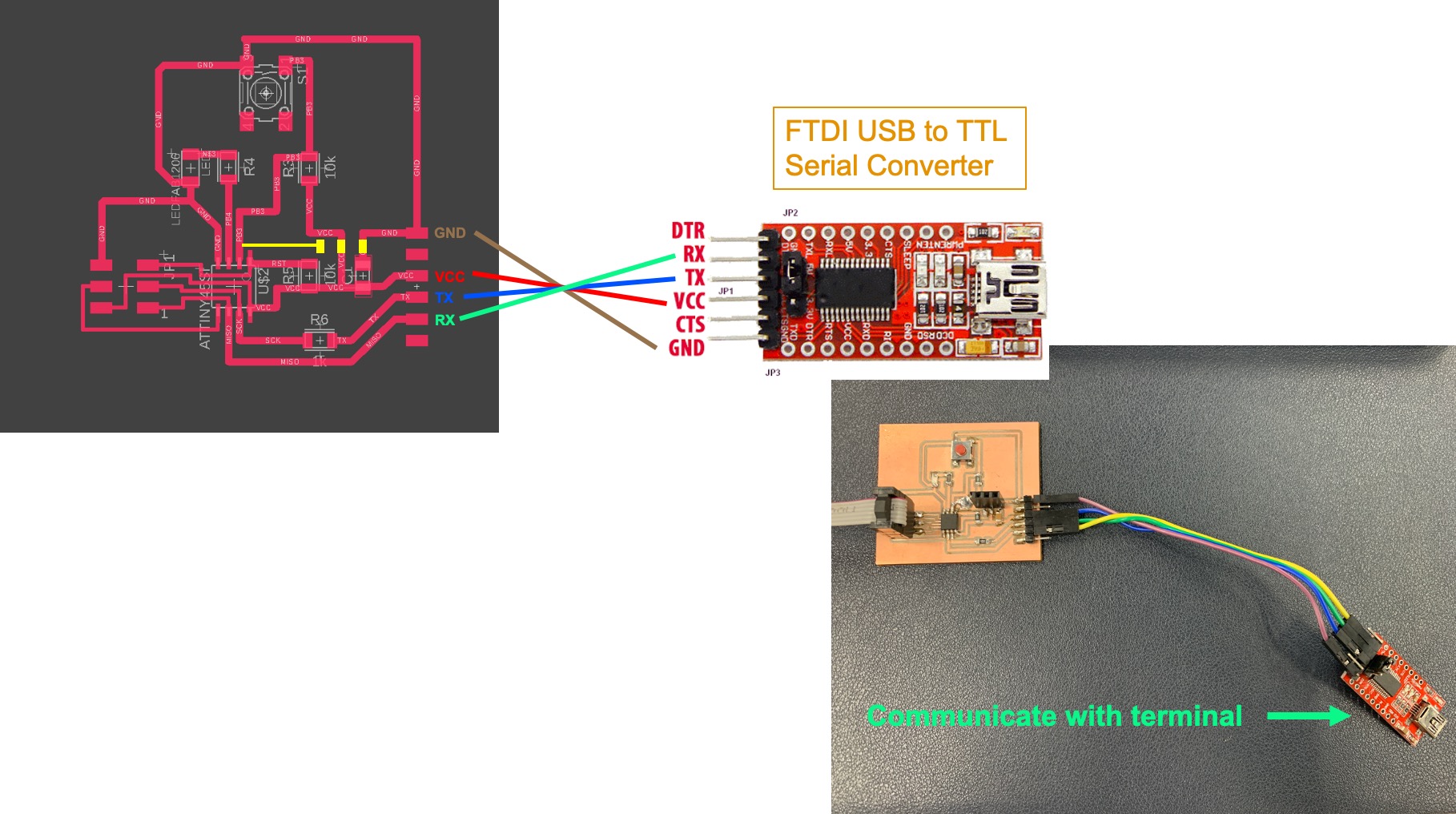
I use FTDI USB to TTL Serial Converter for communicating with the terminal. The USB TTL Serial cables provide connectivity between USB and serial UART interfaces. Also, you can connect the 4 pins by its name, such as, GND, VCC, TX and RX.
For inserting the potentiometer, please be careful the pin layout.
Programming in Arduino IDE
Since Atiny85 do not have serial communication, so I need to use software serial.

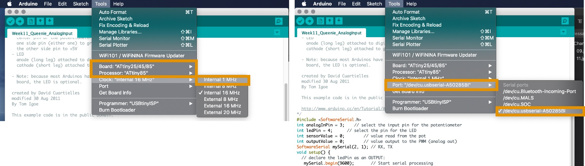
Here is some setting before programming. Setting the board as a Board: ATtiny25/45/85 –> Processor: ATtiny85. There is the different between last time (Internal 15 MHz). This time, setting Clock: Internal 1 MHz –> Port: /dev/cu.usbserial-A50285BI.
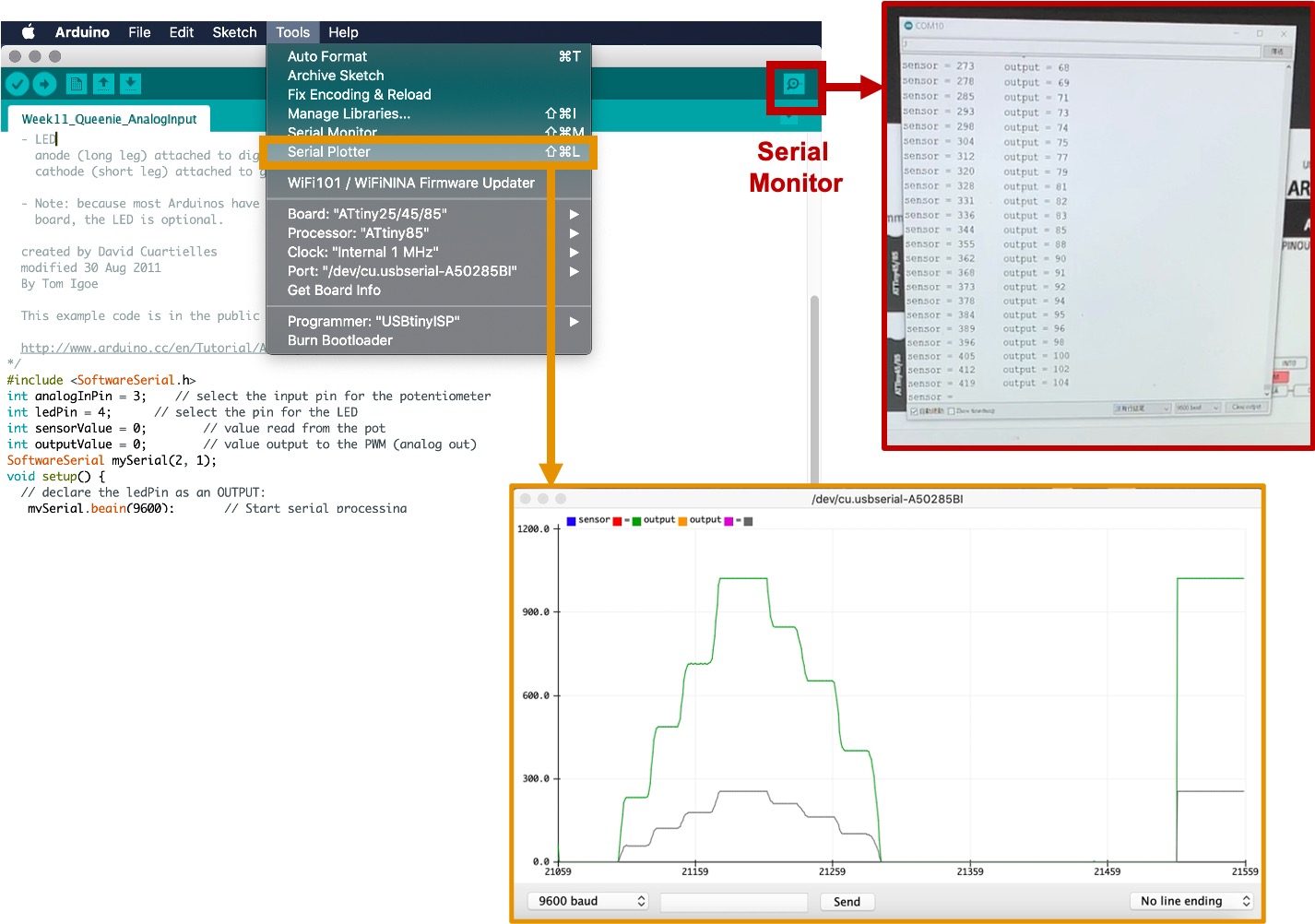
There are 2 different ways for displaying the resutls. If you want to see the grapghic, you may select Serial Plotter. If you want to see the digital number changing, you may select the Serial Monitor.
These are some settings of the program for using potentiometer.
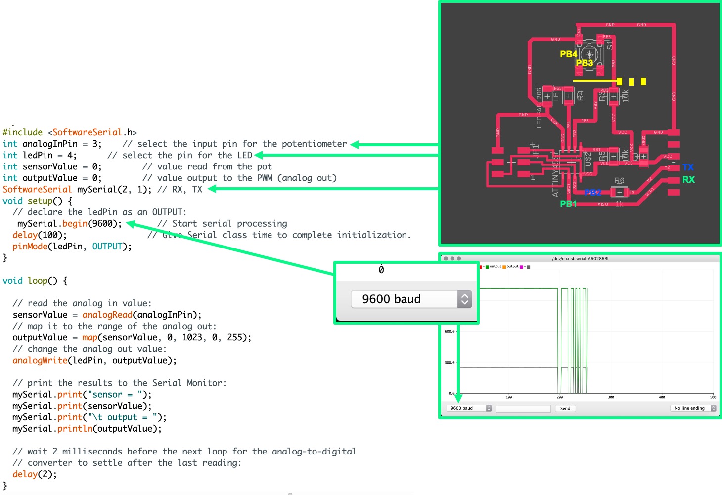
Here is the testing results. The waveform will go up and down because of I rotate the potentiometer into clockwise or anti-clockwise.
Here is the sorce code for my testing.
#include <SoftwareSerial.h>
int analogInPin = 3;    // select the input pin for the potentiometer
int ledPin = 4;      // select the pin for the LED
int sensorValue = 0;        // value read from the pot
int outputValue = 0;        // value output to the PWM (analog out)
SoftwareSerial mySerial(2, 1); // RX, TX
void setup() {
  // declare the ledPin as an OUTPUT:
   mySerial.begin(9600);       // Start serial processing
  delay(100);                // Give Serial class time to complete initialization.
  pinMode(ledPin, OUTPUT);
}

void loop() {

  // read the analog in value:
  sensorValue = analogRead(analogInPin);
  // map it to the range of the analog out:
  outputValue = map(sensorValue, 0, 1023, 0, 255);
  // change the analog out value:
  analogWrite(ledPin, outputValue);

  // print the results to the Serial Monitor:
  mySerial.print("sensor = ");
  mySerial.print(sensorValue);
  mySerial.print("\t output = ");
  mySerial.println(outputValue);

  // wait 2 milliseconds before the next loop for the analog-to-digital
  // converter to settle after the last reading:
  delay(2);
}
}