14. Networking and communications
THIS WEEK CHECKLIST:
- [✓] Linked to the group assignment page.
- [✓] Documented your project.
- [✓] Documented what you have learned from implementing networking and/or communication protocols.
- [✓] Explained the programming process/es you used.
- [✓] Outlined problems and how you fixed them.
- [✓] Included design files (or linked to where they are located if you are using a board you have designed and fabricated earlier) and original code.
Group assignment
This time, I work with my groupmates together to send a message between two projects. CLICK HERE for the detailing of group assignment page.
Individual assignment
- design, build, and connect wired or wireless node(s) with network or bus addresses
First of all, I need to prepare 2 FabTinyISP, 2 ATtiny85 PCB, 2 ICSP and FTDI for serial communication for wired commuication.
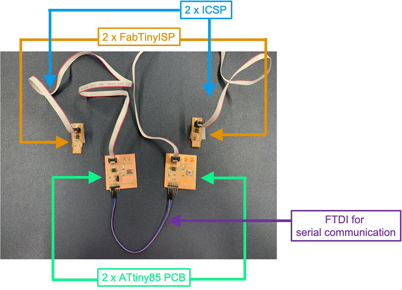
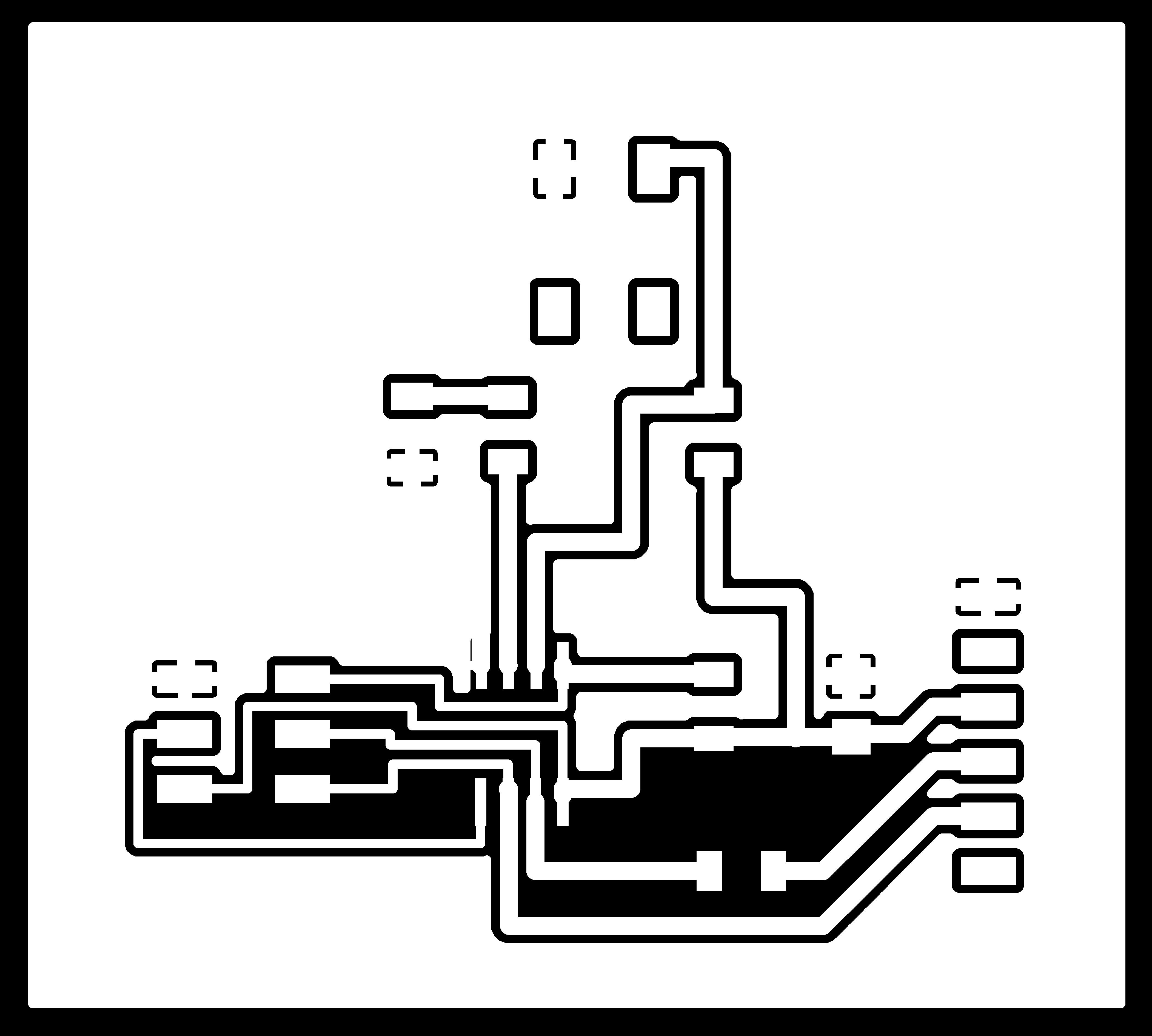
I borrow German’s FabTinyISP since everyone have made their own FabTinyISP. Although I already have 1 ATtiny85 PCB, doing communication I need 1 more board. Therefore, I need to mill 1 more board that I designed in week 07. The production process is happening the same in week07.
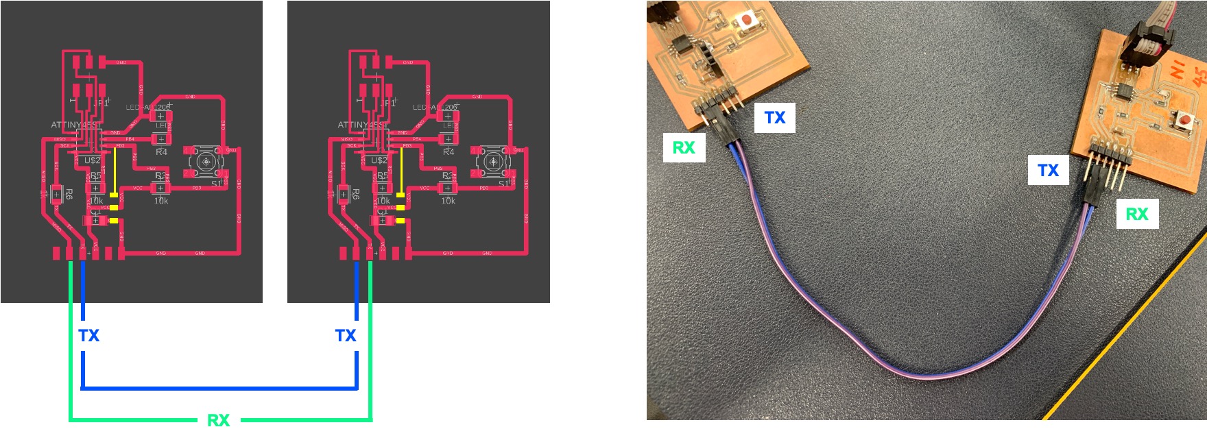
Here is the setting for FTDI for serial communication before starting coummication. RX and TX is corssing connected with 2 PCB.
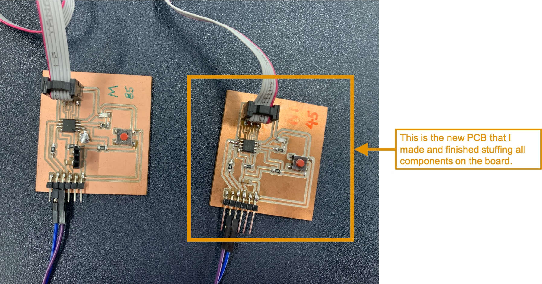
N1 (Right) is the new PCB that I made and finished stuffing all components on the board.
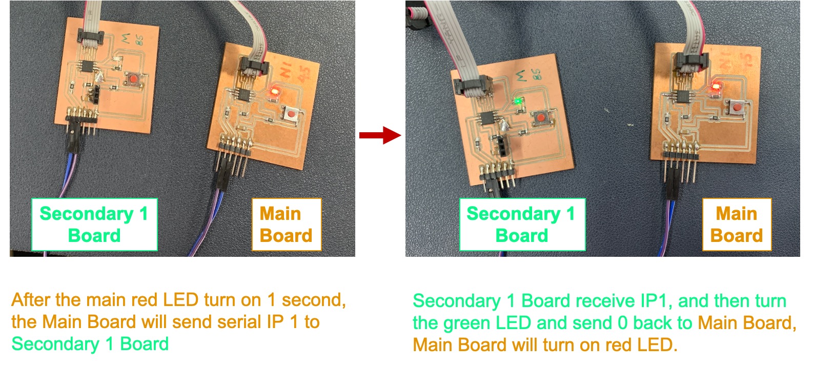
This is how the commuication work. After the main red LED turn on 1 second, the Main Board will send serial IP 1 to Secondary 1 Board. Secondary 1 Board receive IP1, and then turn the green LED and send 0 back to Main Board, Main Board will turn on red LED.
Here is the testing video.
Here is the sorce code of Main Board:
#include <SoftwareSerial.h>    // Arduino SoftwareSerial class
int buttonState = 0;
char ip;
// Create instance of the Software Serial class specifying which device
// pins are to be used for receive and transmit
SoftwareSerial mySerial(1, 2);

// the setup function runs once when you press reset or power the board
void setup() {

   mySerial.begin(9600);       // Start serial processing
  delay(100);                // Give Serial class time to complete initialization.
    digitalWrite(4, HIGH);
     delay(1000);
    Serial.println('1');
}

// the loop function runs over and over again forever
void loop() {
 if (Serial.available()){
  ip = Serial.read();
   Serial.println('1');
    if (ip == '0') {

  digitalWrite(4, HIGH);   // turn the LED on (HIGH is the voltage level)
  delay(100);                       // wait for a second
  digitalWrite(4, LOW);   // turn the LED on (HIGH is the voltage level)
  delay(100);                       // wait for a second

   }

else {digitalWrite(4, LOW); }
 <br>
<br>
Here is the sorce code of Seconadry 1 Board:
#include <SoftwareSerial.h>    // Arduino SoftwareSerial class
int buttonState = 0;
char ip;
// Create instance of the Software Serial class specifying which device
// pins are to be used for receive and transmit
SoftwareSerial mySerial(1, 2);

// the setup function runs once when you press reset or power the board
void setup() {

   mySerial.begin(9600);       // Start serial processing
  delay(1000);                // Give Serial class time to complete initialization.

}

// the loop function runs over and over again forever
void loop() {
 if (Serial.available()){
  ip = Serial.read();
   Serial.println('0');
    if (ip == '1') {

  digitalWrite(4, HIGH);   // turn the LED on (HIGH is the voltage level)
  delay(100);                       // wait for a second
  digitalWrite(4, LOW);   // turn the LED on (HIGH is the voltage level)
  delay(100);                       // wait for a second

   }

else {digitalWrite(4, LOW); }

}
<br>
<br>
File Download (Same with Week07)
Fusion360 Schematic Design
Fusion360 PCB Design
PCB Milling:
PCB_Trace
PCB_Outline