6. 3D Scanning and printing
This week I worked on drawing container box for my final project and started to getting used to the documentation process.
Group assignment: Design Rules for our 3D printers
Print a series of test objects on the different 3D printers we have to characterize them :
Design Rules STL Test File List
| Design Rule | Test Layer Height |
|---|---|
| Nozzle Orifice | 0.3 mm |
| supported overhang | 0.1 mm |
| supported clearance | 0.1 mm |
| angle | 0.1 mm |
| overhang | 0.1 mm |
| bridging | 0.1 mm |
| wall thickness | 0.1 mm |
| dimensions | 0.1 mm |
| anisotropy | 0.1 mm |
| surface finish | 0.1 mm |
In the Fablab HONG KONG CMASS ISPACE there is 2 available 3d printers FFF (Fused Filament Fabrication):
- Raise3D N2 Plus (Build size 600 x 305 x 305 mm)
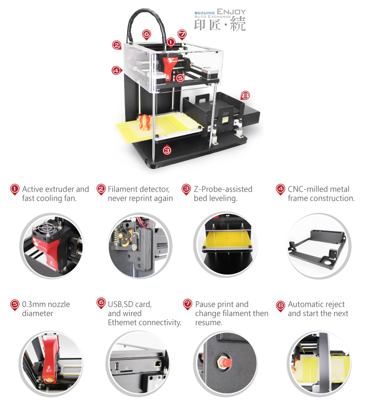
- 86DUINO ENJOY AUTO (Build size 150 x 100 x 100 mm)
Why using 86DUINO ENJOY AUTO Exchange and 0.1 mm layer heights
The 86Duino ENJOY AUTO Exchange is built with CNC machined metallic frame to provide a rigid structure for the printer assembly, which helps minimize vibration and provides a stable environment to deliver optimal print quality. The intuitive 86Duino Enjoy is designed with simple calibration, enabling you to easily enjoy and replicate your creation with minimal effort.
I set 86DUINO ENJOY AUTO Exchange 3D print to print all my parts at 0.1 mm layer thicknesses with a 0.3 mm nozzle orifice size. It is time consuming but I got the best results for observation. I teach our students at the Fab Lab HONG KONG CMASS ISPACE to consider the amount of time they have to print their design and optimize for that time, this usually results in larger scaled prints at 0.2 mm layer height.
Raise3D N2 Plus and 0.2 mm layer heights
| Spec. | Value |
|---|---|
| Build Volume | 600 X 305 X 305 mm |
| Layer Height | 0.1mm : 0.3mm |
| Nozzle Diameter | 0.4mm |
| Max heatedbed/ Hot End | 120 / 300 |
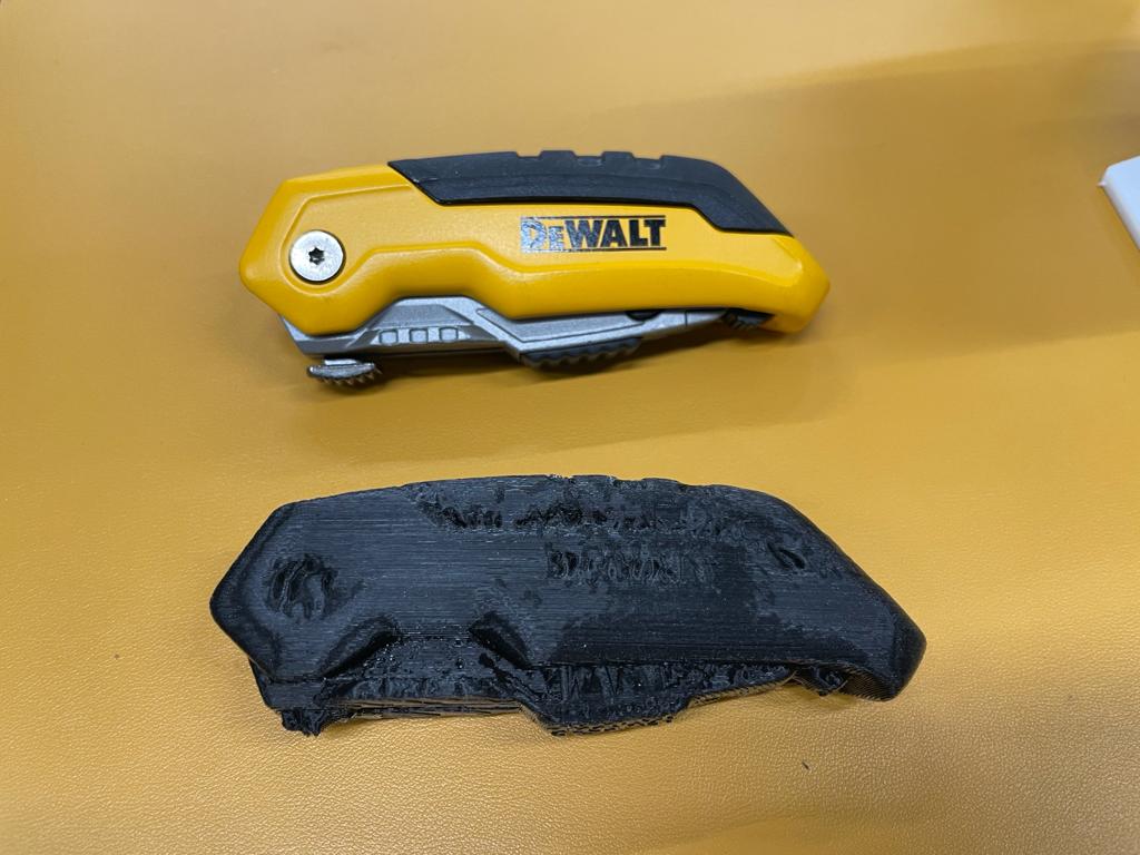
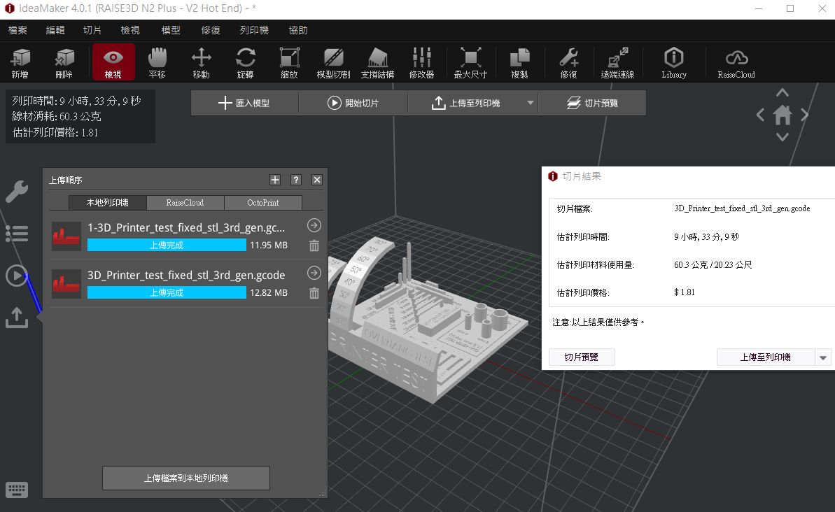
First, I downloaded the model from (Thingiverse), I sliced the model using the ideaMaker. I printed it with layer height 0.2mm, 20% infill, and of course without any supports. This model should test the maximum overhang angle that the machine can print smoothly, the maximum bridging length, clearance, stringing, and hole diameter test.
Individual assignment
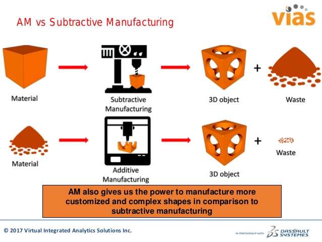
Design and 3D print an object (small, few cm3, limited by printer time) that could not be made subtractively
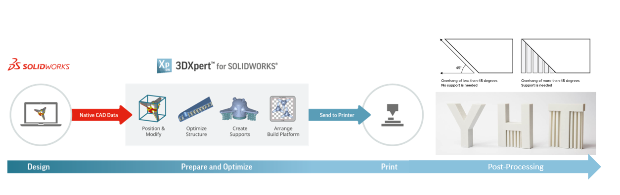
Additive vs Subtractive Manufacturing
3D Printing Workflow
The 3D printing workflow consists of four steps usually. They are:
- Designing
- Slicing
- Printing
- Post Processing
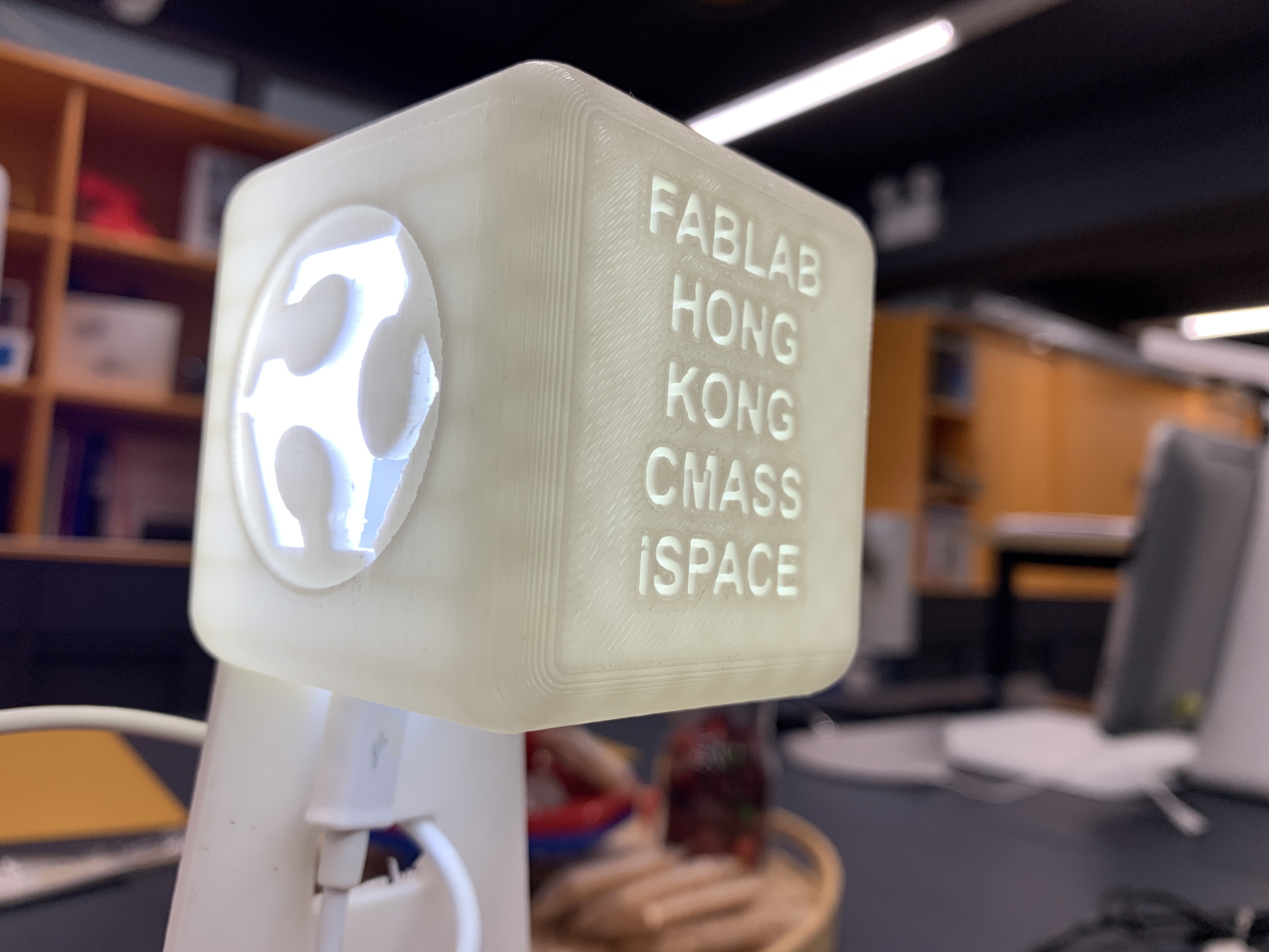
Custom Promotional Table Lamp Cube (FABLAB HONG KONG CMASS iSPACE)
For promotion aim, I decide on design a Custom Promotional Table Lamp Cube (FABLAB HONG KONG CMASS iSPACE with 4 face fablab logo). It is impossible to make such a design using traditional subtractive methods because the inside of the cube cannot be subtracted away. But this is easily possible using a 3D printer as it is building layer by layer. In this print I used PLA as the print material.
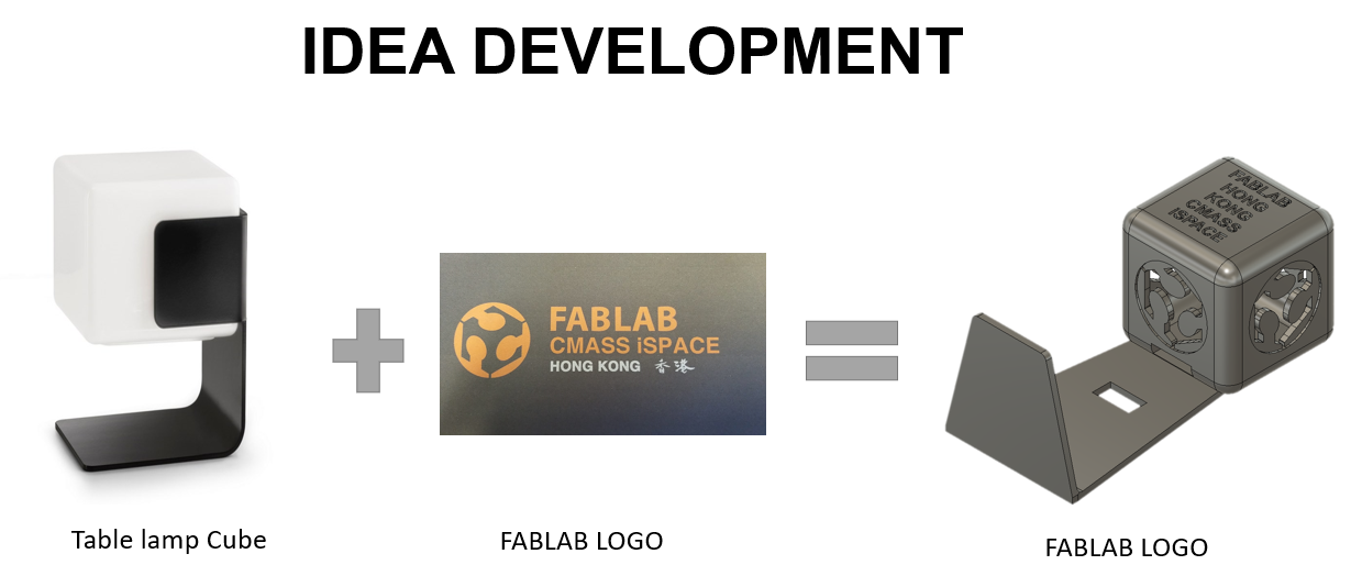
Designing FABLAB HONG KONG CMASS iSPACE Promotional Table Lamp Cube
I opened Fusion360 and started designing my thing. I created a new sketch and draw a 60mm square and extruded it with value 50mm. Creating a cube of 60X60X60mm. After that, I draw a fablab logo on different four faces of the cube and add the name of FABLAB HONG KONG CMASS iSPACE on the top face. Fainally, I add the table lamp stand to complete the cad model (.f3d).
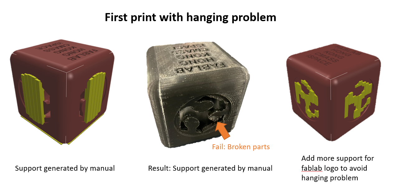
The result was exported to (.STL) file and opened in Raise3D Ideamaker. The slicing profile was the printer default 0.1mm fine print and add support by manual for PLA that the CUBE was printed out.
To get the best quality a 0.1mm layer height were used. The printing time is about 15 hours. The print temperature for the PLA was 205C. The Bed temperature was for raft 60C.
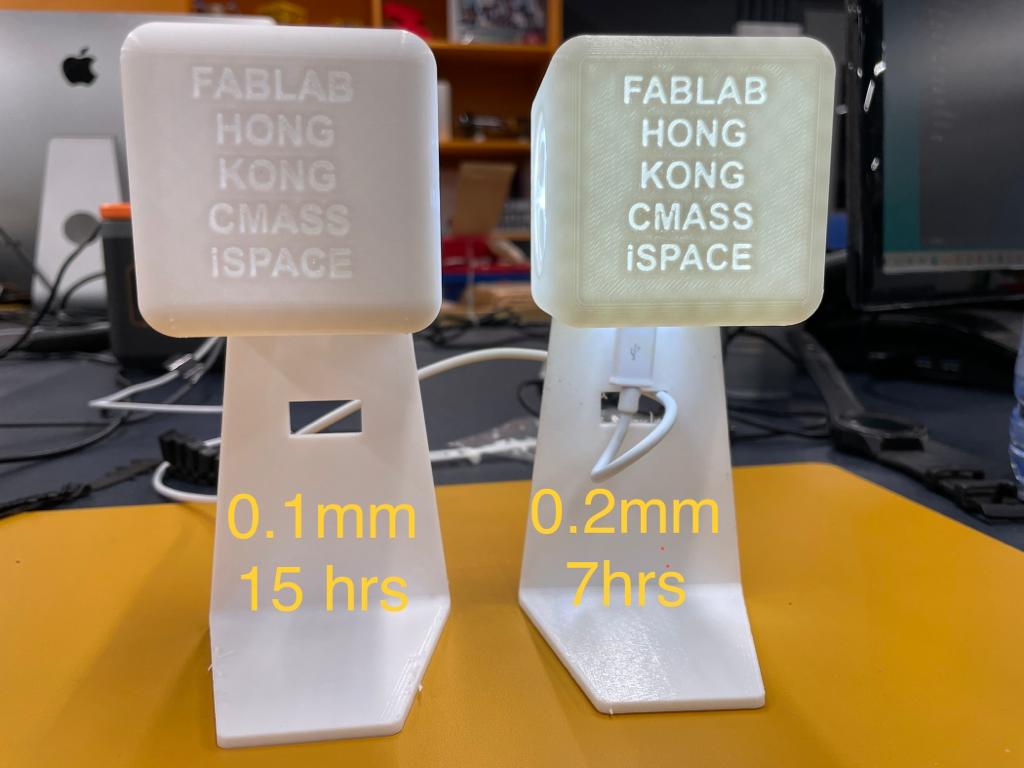
Finally, I setting 0.2mm layer height to save time. The printing time is only 7 hours.
Hero Shot
3D scan an object
I am using the HP sprout all in one desktop with scanner to scan my object. The special feature of this computer is including a 3D scanning with 3D capture stage.
Step 1: I open 3D scan app and set up for scanning.
Step 2: Next I would be clear the back ground in the scan area of the device. I positioned the object. Next I started the scan and I rotated 360 degrees. I took the cycle from different angles.
Step 3: I exported this with (.OBJ) file.