9. Embedded programming
Group assignment
Compare the performance and development workflows for other architectures
Individual assignment:
This weeks assignment was to read a microcontroller datasheet and program my board to do something using as many environments.
ATtiny 85 Datasheet
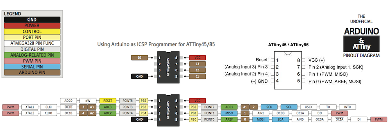
I read a datasheet on attiny85, I think that the most important is learn about the pin configuration and better understanding of the Microcontroller. You can download Data Sheet and Sparkfun ‘Tiny AVR Programmer Hookup Guide’ from here. The following colorful pin lay-out of the ATtiny85 is from this site.
This is a quick reference sheet for using the ATtiny85.
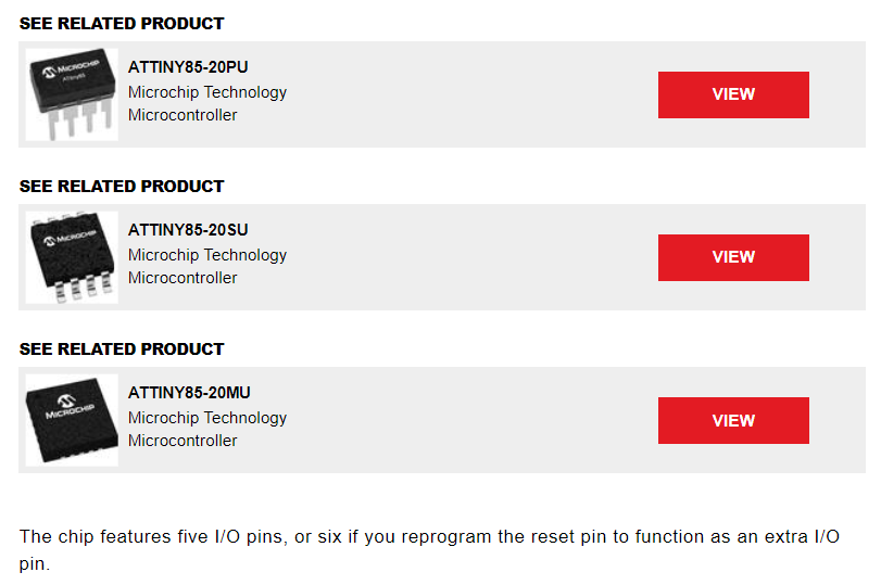
Microchip Technology’s ATtiny85 is available for around $1-$2, depending on the quantity and version you select, such as:
- Through-hole ATtiny85-20PU
- SOIC ATtiny85-20SU
- QFN format ATtiny85-20MU
Overveiw from Datasheet
I can understand the general parameters such as architecture, memory, operating voltages, speed, etc from features.
Attiny85 Arduino Pinout Description
The most important part of the pin configuration is shown. Each of the I/O pins on the ATtiny85 are capable of digital input and output. Analog Input and Output There are two analog outputs and three analog inputs.
Program your board to do something, with as many different programming languages and programming environments as possible.
Programming ATting85 in Visual Studio Code
Helper extension to simplify code compilation and flashing for AVR chips. This extension creates a C/C++ build system based on “make” in currently open folder. It needs make, avr-gcc, and avrdude installed. It uses C/C++ extension to provide language support.
AVR Helper - Visual Studio Marketplace
Features - Demo: source highlighting and build.
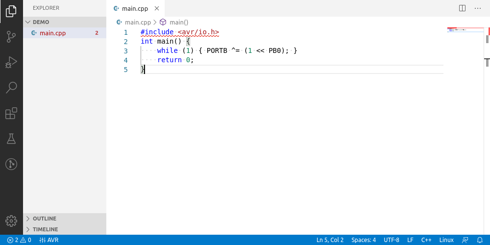
The AVR Helper adds five items to the window status bar:
Status bar: AVR (command: Perform initial setup) Displayed as AVR
This is the starting point to configure build system.
- Makefiles are created when this item is clicked
- Step 1: choose avr-gcc executable file
- Step 2: choose avrdude executable file
- Step 3: choose avrdude.conf
- Step 4: choose additional source libraries
Getting started with Arduino IDE
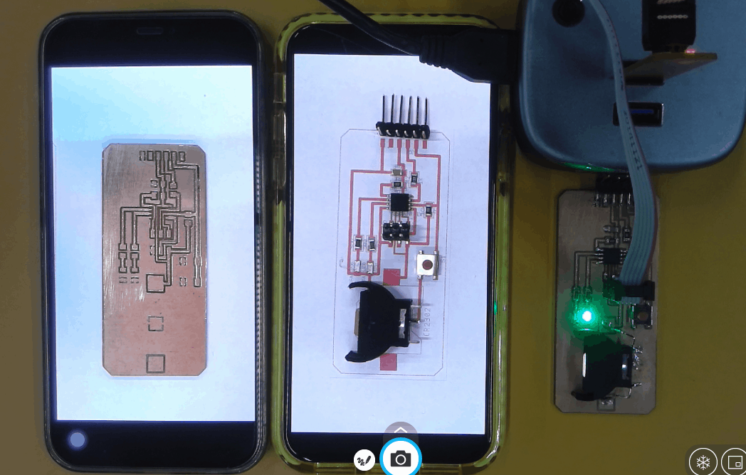
I used the PCB than I created in my assignment of Electronic design.
Steps to add additional boards
-
Go to Arduino Preferances and there in the text field add a link https://raw.githubusercontent.com/damellis/attiny/ide-1.6.x-boards-manager/package_damellis_attiny_index.json then click ok
-
Then go to the boards manager and install new board files as required
-
Now goto tools then to Boards and select the Microcontroller which you are using, in my case it was attiny 85 with 16Mhz internal clock and programmer as USBTINY.

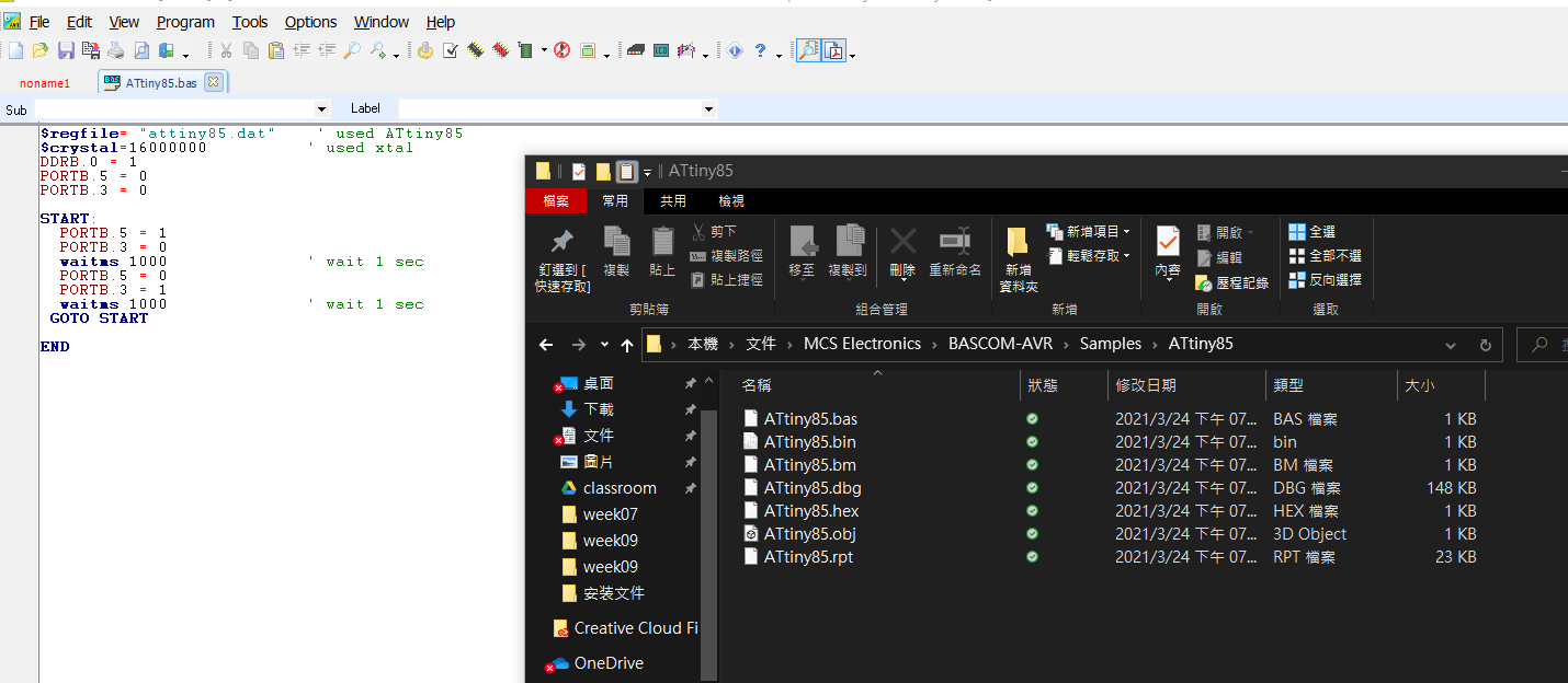
Programming ATting85 in Bascom
As a first step, open the program and created a new file by clicking on FILE and choosing NEW. this will create a new window for program. Once the file is created, we start the programming. First of all, we must make the programming of the microcontroller and the crystal that we are going to use. for this case we will use an attiny 85 with its internal crystal of 16 MHz. After press F7 or compile program icon, HEX format file will be generated. It can upload to target board using fabtinyisp.
Programming ATting85 in Arduino IDE
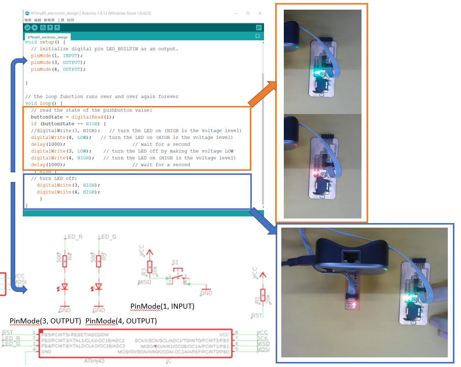
This weeks assignment was to program our board to make it do something. My board was having 1 Push button and 2 LEDs. So I decided to program it in a way that pushing this button would be changing the state of LEDs from mutual flash to turn on both LEDs. s
int buttonState = 0;
// the setup function runs once when you press reset or power the board
void setup() {
  // initialize digital pin LED_BUILTIN as an output.
  pinMode(1, INPUT);
  pinMode(3, OUTPUT);
  pinMode(4, OUTPUT);

}

// the loop function runs over and over again forever
void loop() {
  // read the state of the pushbutton value:
  buttonState = digitalRead(1);
  if (buttonState == HIGH) {
  digitalWrite(3, HIGH);   // turn the LED on (HIGH is the voltage level)
  digitalWrite(4, LOW);   // turn the LED on (HIGH is the voltage level)
  delay(1000);                       // wait for a second
  digitalWrite(3, LOW);    // turn the LED off by making the voltage LOW
  digitalWrite(4, HIGH);   // turn the LED on (HIGH is the voltage level)
  delay(1000);                       // wait for a second
   } else {
  // turn LED off:
    digitalWrite(3, HIGH);
    digitalWrite(4, HIGH);
     }
I use the above program to control both LEDs flash mutually when the button is not pressed. Both LEDs will turn on when the button is pressed. II can change the delay() to control the time of flash.
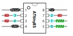
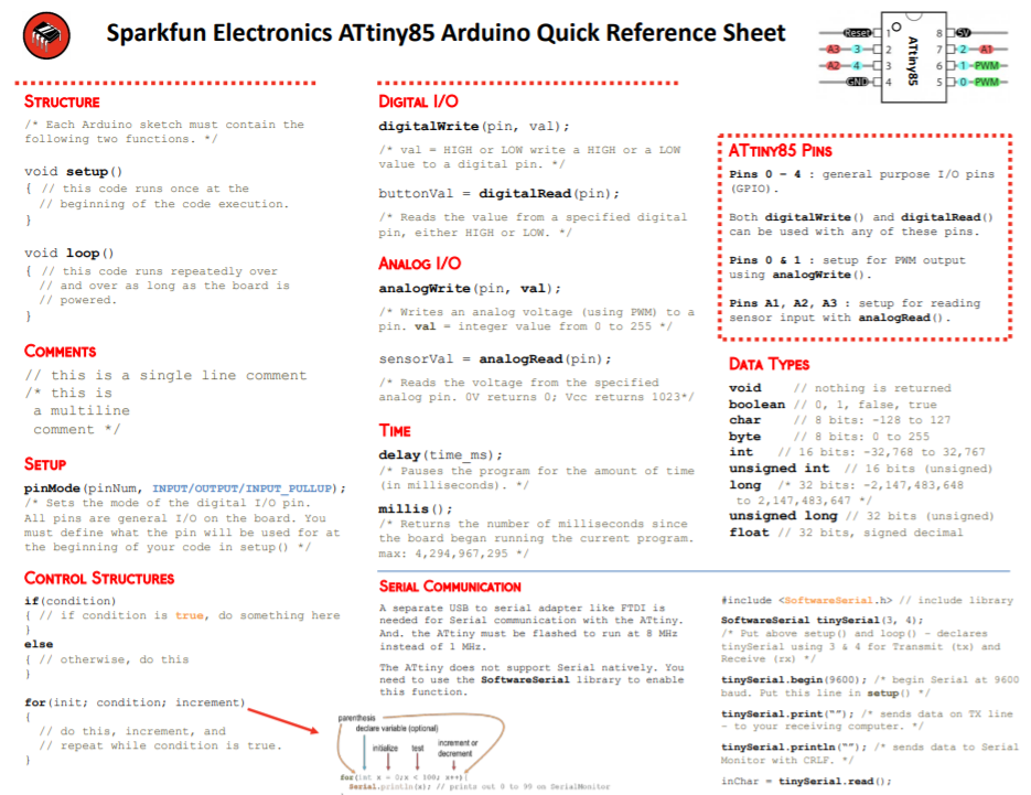
Programming Pins
Tip: Looking for a quick reference guide for the ATtiny85?
Learning Outcome
After reading the ATtiny85 data sheet, I can find out the pin funtion. Pin4 is GND. Pin8 is Vcc. All remain pin can use as digital. Only PB0,1,3 and 4 can be used as PWM control. I programe the ATtiny85 with Arduino IDE. It need a SPI ISP to upload programe.