4. Computer Controlled Cutting
This week I worked on making a Hong Kong Fablab logo sticker with Brother ScanNcut and a parametric press-fit construction kit for my individual projects, as well as characterizing our lasercutter’s focus, power, speed, rate, kerf, and joint clearance for our group project.
About CAM-Computer Aided Manufacturing, there are various machines in each Fablab. It is a headache to configure them and set various parameters. So I like fab module that is compatible with almost all devices. No matter which format file you input, it can calculate the working path of the machine, and then output the command to the corresponding machine.
Vinyl Cutting
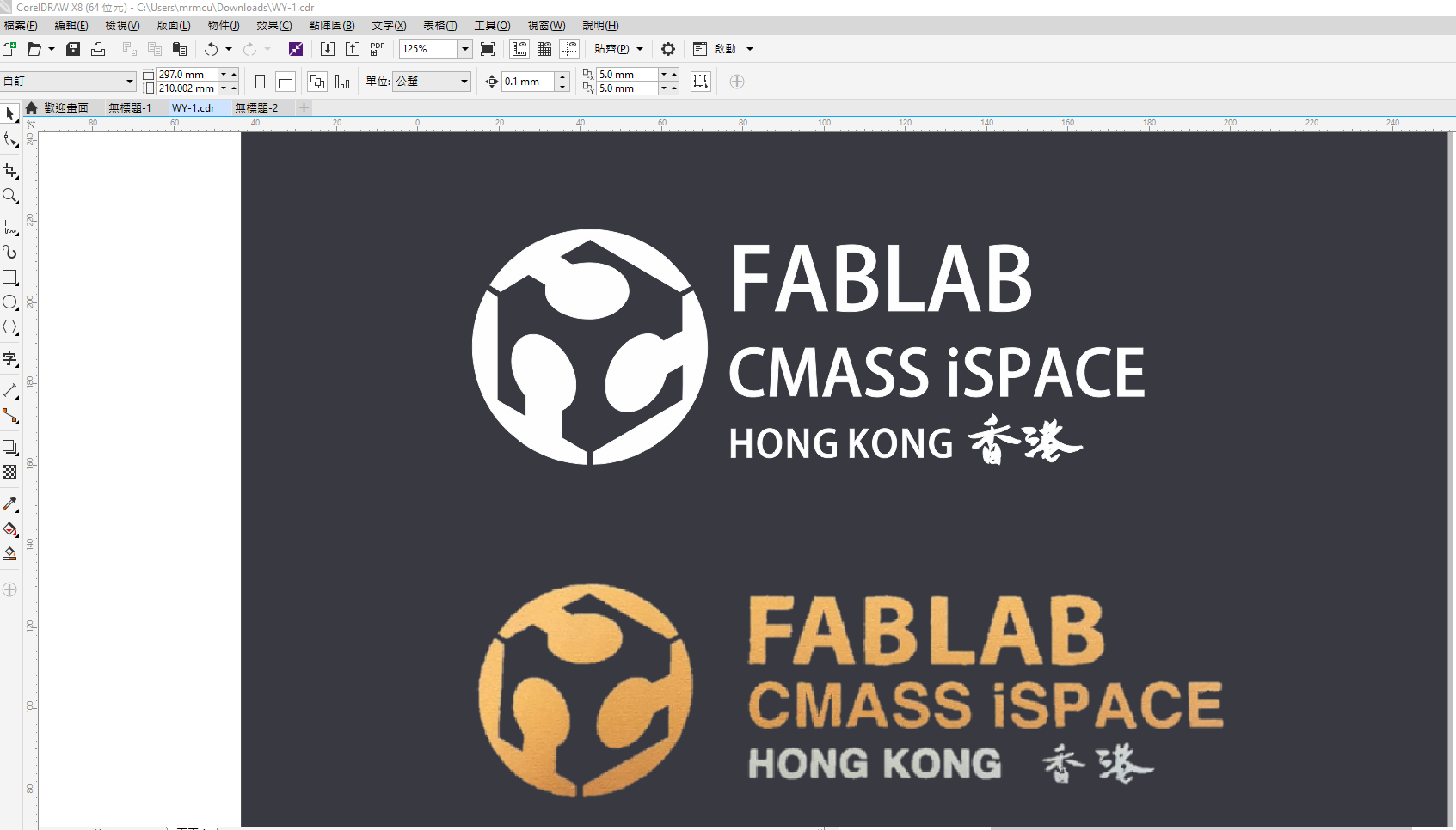
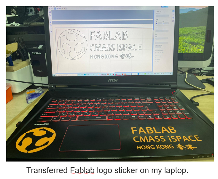
I want to create my original stickers in this assignment. Sticker design is from our fablab logo. Finally, I transferred a logo sticker on my laptop. HK_FABLAB LOGO (.cdr) (.svg)
Sticker Outlook
Machine settings and cutting
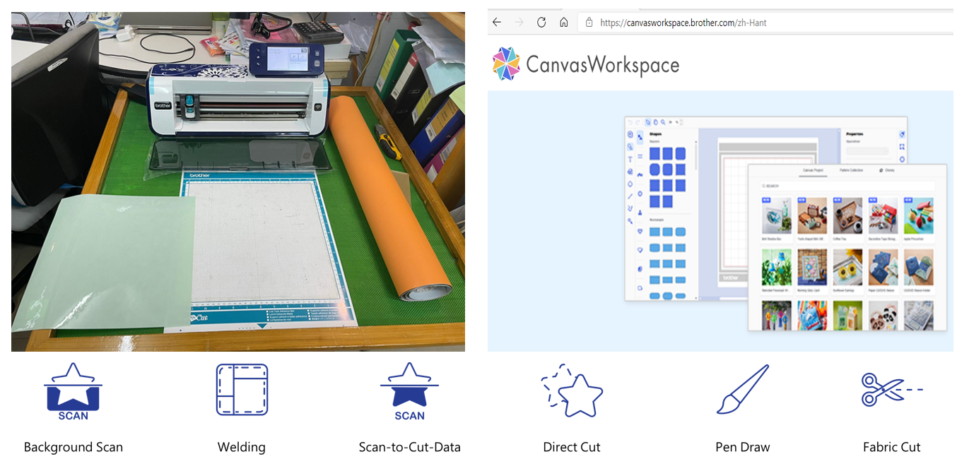
I used Brother ScanNCut CM900 to cut a sheet of sticker paper. I downloaded and install CanvasWorkspace which works with Brother ScanNCut CM900.
| Machine CM900 | Crafting Workspace |
|---|---|
| Work Area | 11.75” x 11.75” |
| Optional Extended Work Area | Cutting the acrylic for the sorting track |
| Standard Blade | max 0.8 mm |
| Deep Blade | max 1.5 mm |
| Adjustable Holder Pressure | 19 levels |
| Cutting Speed | 5 levels |
| Cutting Materials | Fabric Max 1.5 mm (may vary); Paper (max 0.8 mm): Printer/ Scrapbook/ Cardstock/ Velum/ Tracing/ Poster board; Fabric: Thin cotton/ Flannel/ Felt; Others: Magnet/Sticker or Seal |
As CanvasWorkspace need a design file of SVG format, I exported Coreldraw file(.cdr) as SVG format, and import SVG into CanvasWorkspace.
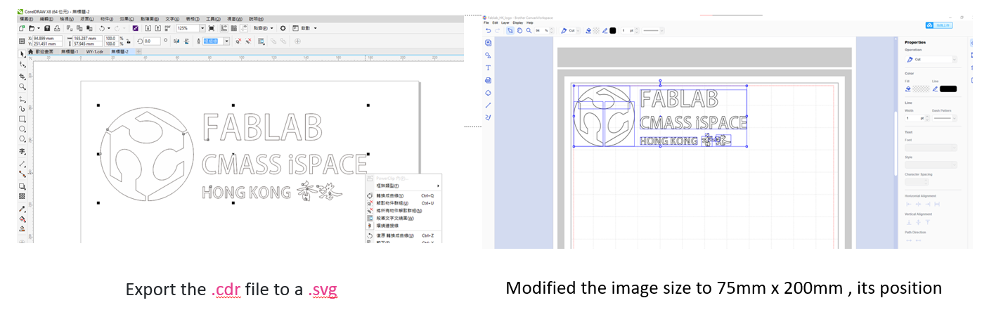
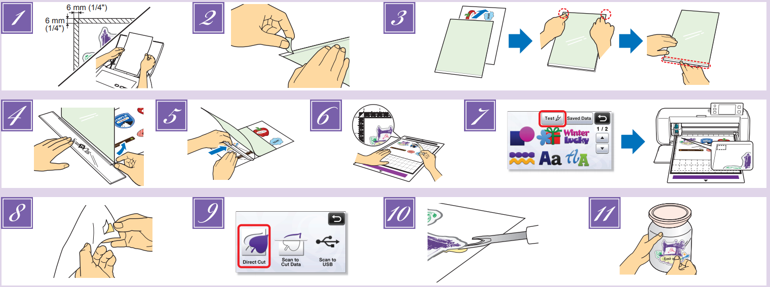
I modified the image size, its position and wifi send the file into Brother ScanNCut CM900. These are followings setting.
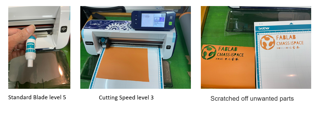
The whole process takes 4 minutes. Use masking tape to fix the sticker and tranfer the stick on my laptop.
Parametric Press-fit Construction Kit
CAD-Computer Aided Design
Tools such as Fusion360 can decompose 3D objects into 2D parts with DXF4Laser. It is very suitable for designing components that require parameterized control (for example, uniformly setting the diameter of the table legs, and modifying the parameters to modify the size of all the same components).
Creating my press-fit kit
The laser cutting machine has a wide range of uses, such as marking, cutting, engraving and so on.
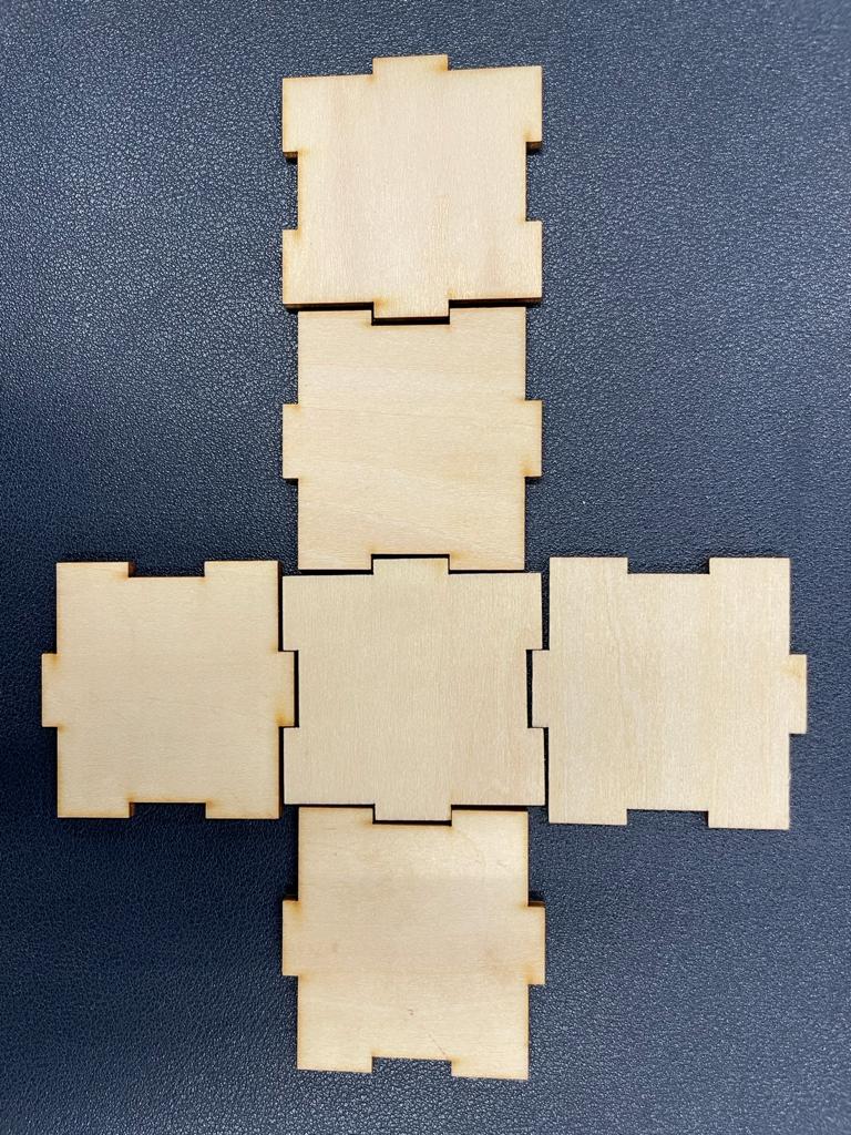
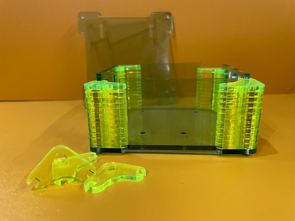
I want to create my Screw storage Box in this assignment. It also can use in my final project. The box contains 4 elements (conner, boundary, Bottom, Top). I draw the original file with Fusion360. It is a parametric software. Use the laser engraving machine to make the shell of the box, and change parametric to control the slot size from material thickness.
Conner Draft design
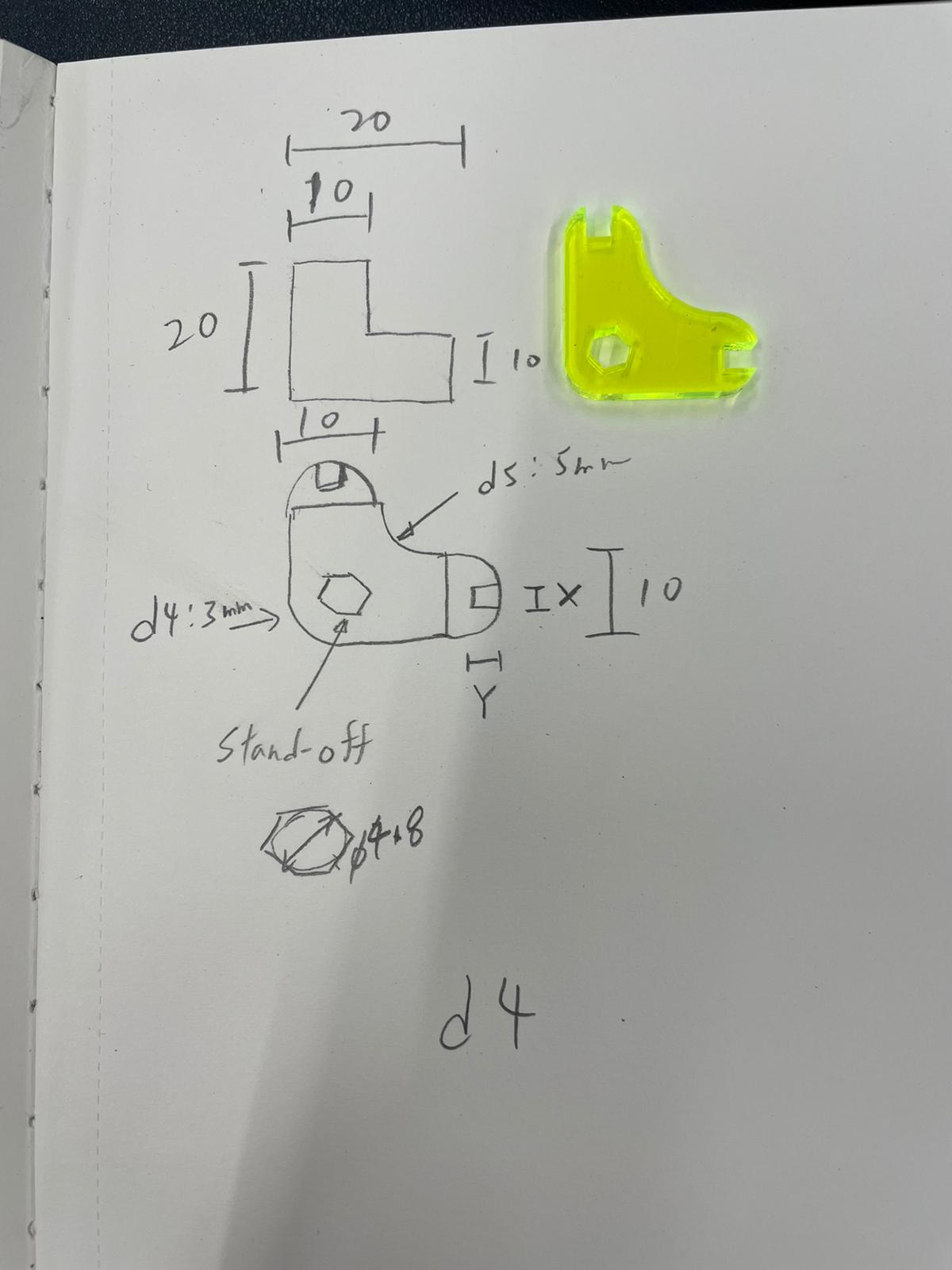
Press-fit means a joint that can be repeatedly assembled and disassembled. This kind of modularization requires a parameter to control the design of the object, which is convenient for cutting materials of different thicknesses. I used the setting method of parameter modeling and added the material thickness as Control the parameters of the buckle position, let the slot hole and joint automatically convert the appropriate size according to the material thickness
This process was not as simple as I hoped having drawn all my sketches output to DWG within Fusion360. Having discovered the Plugin dxf for Laser .
Finally, I export the file (.f3d)with DXF4Laser in Fusion360 and open with corldraw for Lasercut. Lasercut file download (.cdr)
I got these all exported into the same file for cutting. I tried speed 1.7 and power 90% first, but still didn’t cut through the 3mm aryclic sheet. Finally, I tried speed 0.9 and power 100%. This attempt was successful and cut without any problems. The above parameters are different from the original factory settings. The reason is that the laser cutting machine has been used for 13 years since 2008, and its power has been reduced by about 30%.
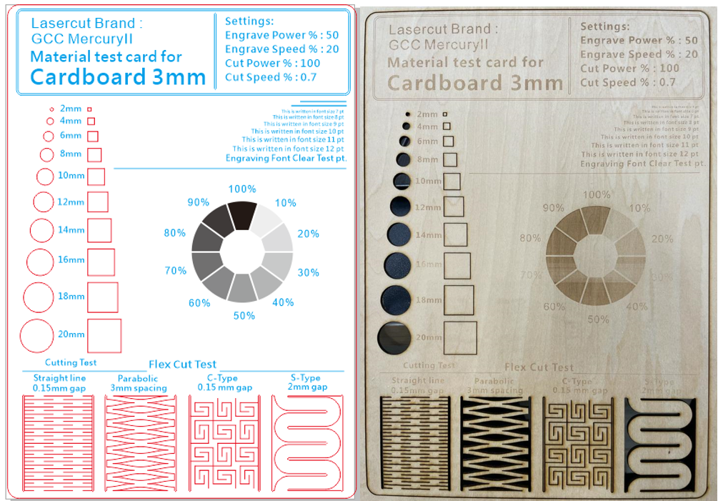
Group assignment - Laser cutter characterization
For this group assignment, I were tasked with characterizing GCC MercryII lasercutter’s focus, power, speed, rate, kerf, and joint clearance.
Here is the file (.cdr) for group project.
For optimal parameter of kerf
First, we made the data for testing the optimal kerf parameters. I used a tool to generate kerf check parts (by Mr. Daisuke Doyo in Fab Academy 2018). I generated a kerf test parts to check from 3.1 mm to 2.81 mm in 0.01 mm intervals. The parts I made are here:
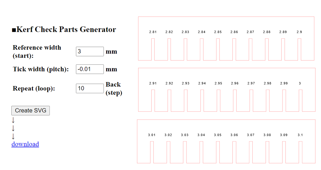
Here is the file (kerf_01.svg) (kerf_02.svg) (kerf_03.svg) for group project.