5. Electronics Production
This week task as below:
- Individual assignments
Make an in-circuit programmer by milling and stuffing the PCB, test it, then optionally try other PCB fabrication process.
Individual assignment
This week is very challenging for me. This is my first time to learn in-circuit programmer and PCB fabrication process.
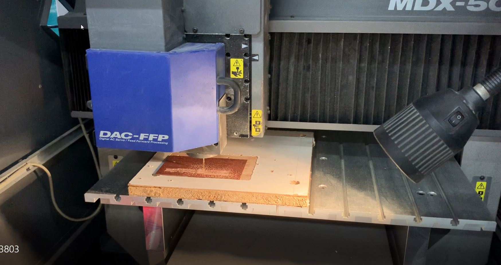
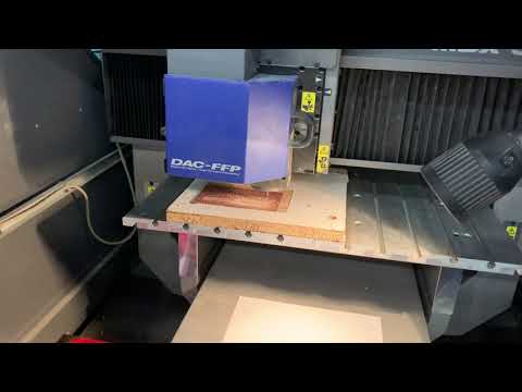
For our laboratory, the machine we used is called Roland-MDX500 for machine milling. In our school, the Roland-MDX500 have already run for many years.
Engrave the circuit trace: Carving V-Bit Cut out the outer edge of the entire borad: 1/32 flat endmill
Trace test for milling
In order to test the thickness of the milling, we used the below diagram to test the milling situation.

Produce the In-Circuit by using milling
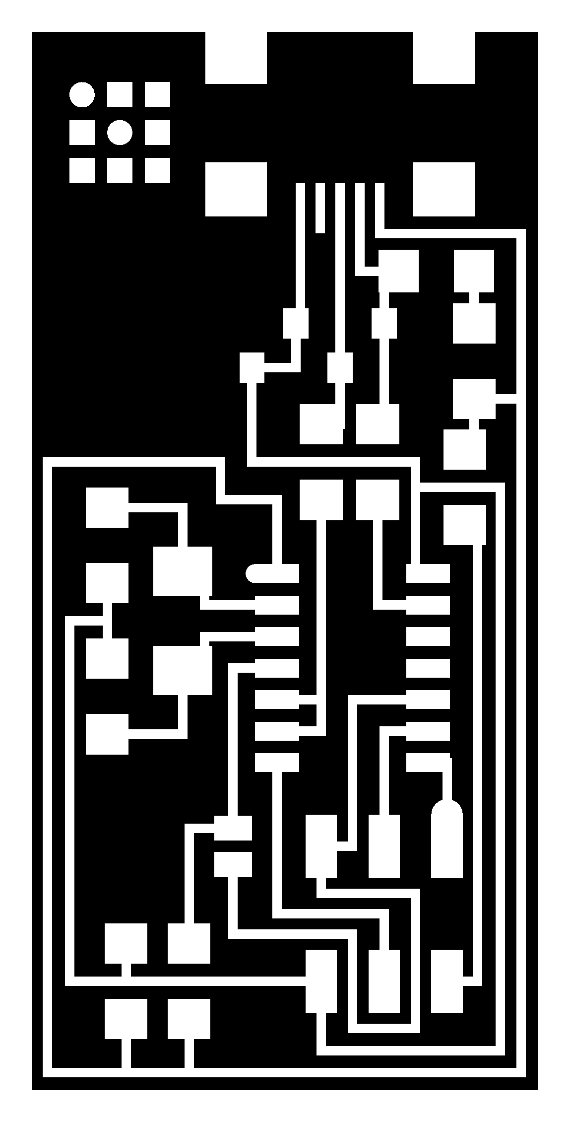
Step 1 - FabTinISP Minimal from Brian
In this Brian website, I can download the png file which is used for milling.
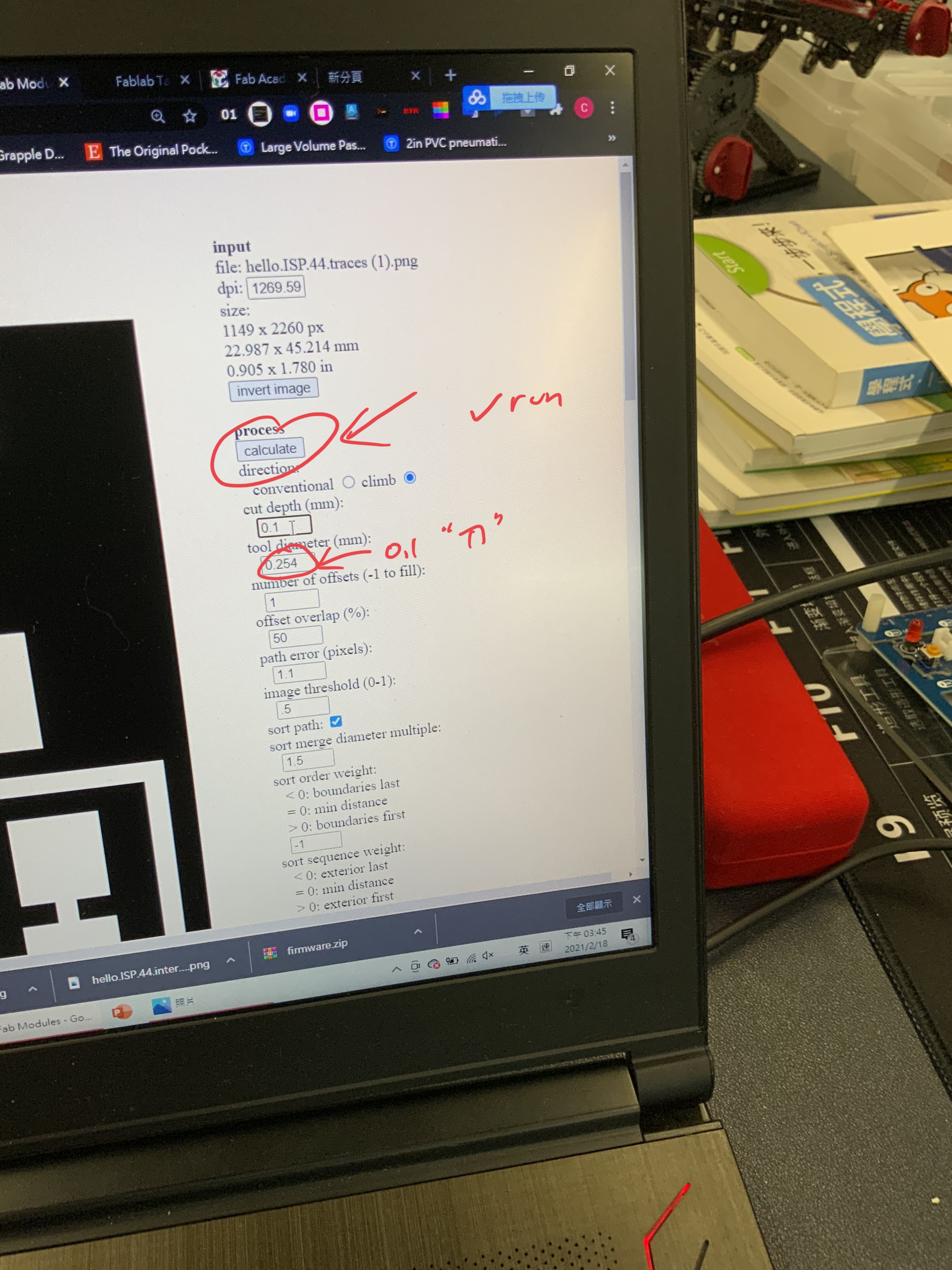
Step 2 By using the website fabmodules.org, I need to convert the png file into G code.
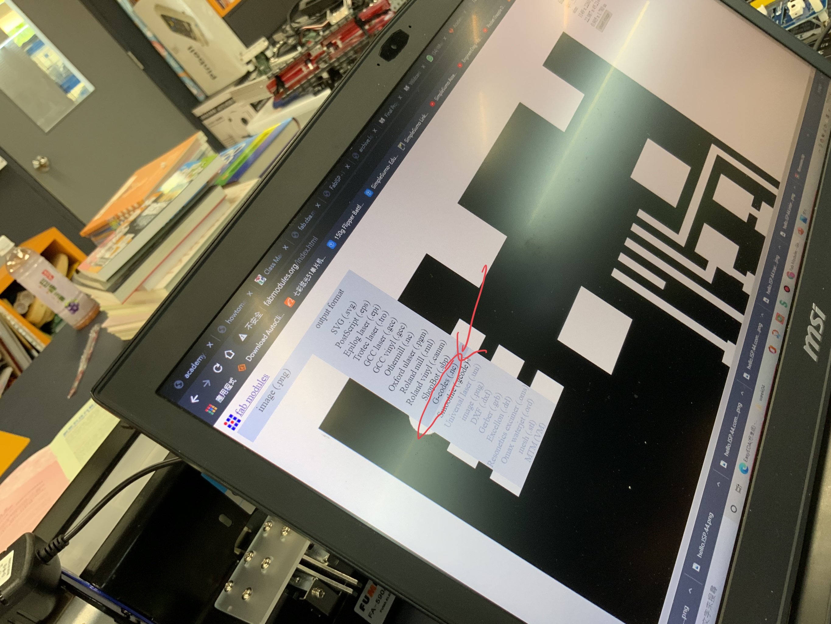
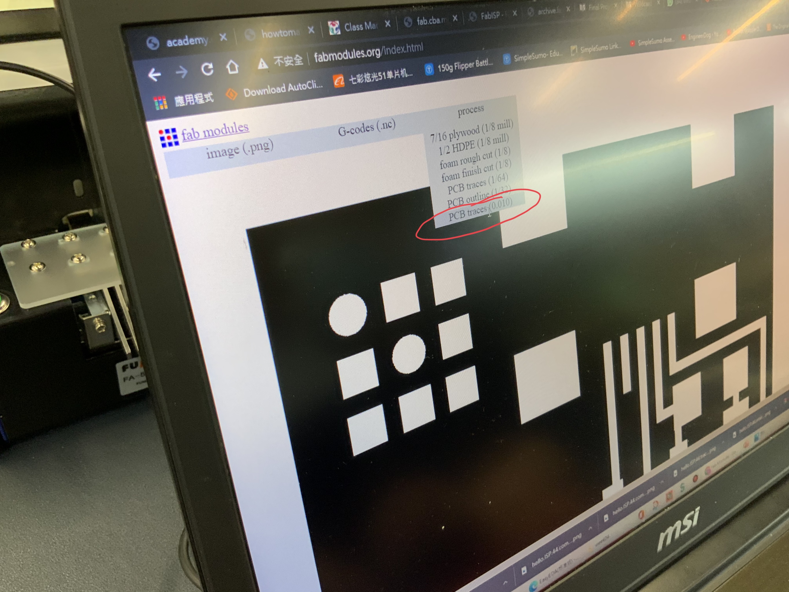
Step 3
The process for using PCB traces is 0.010
Step 4
The tool diameter is 0.1 mm. After making the correct setting, I can click calculate to start up the process.
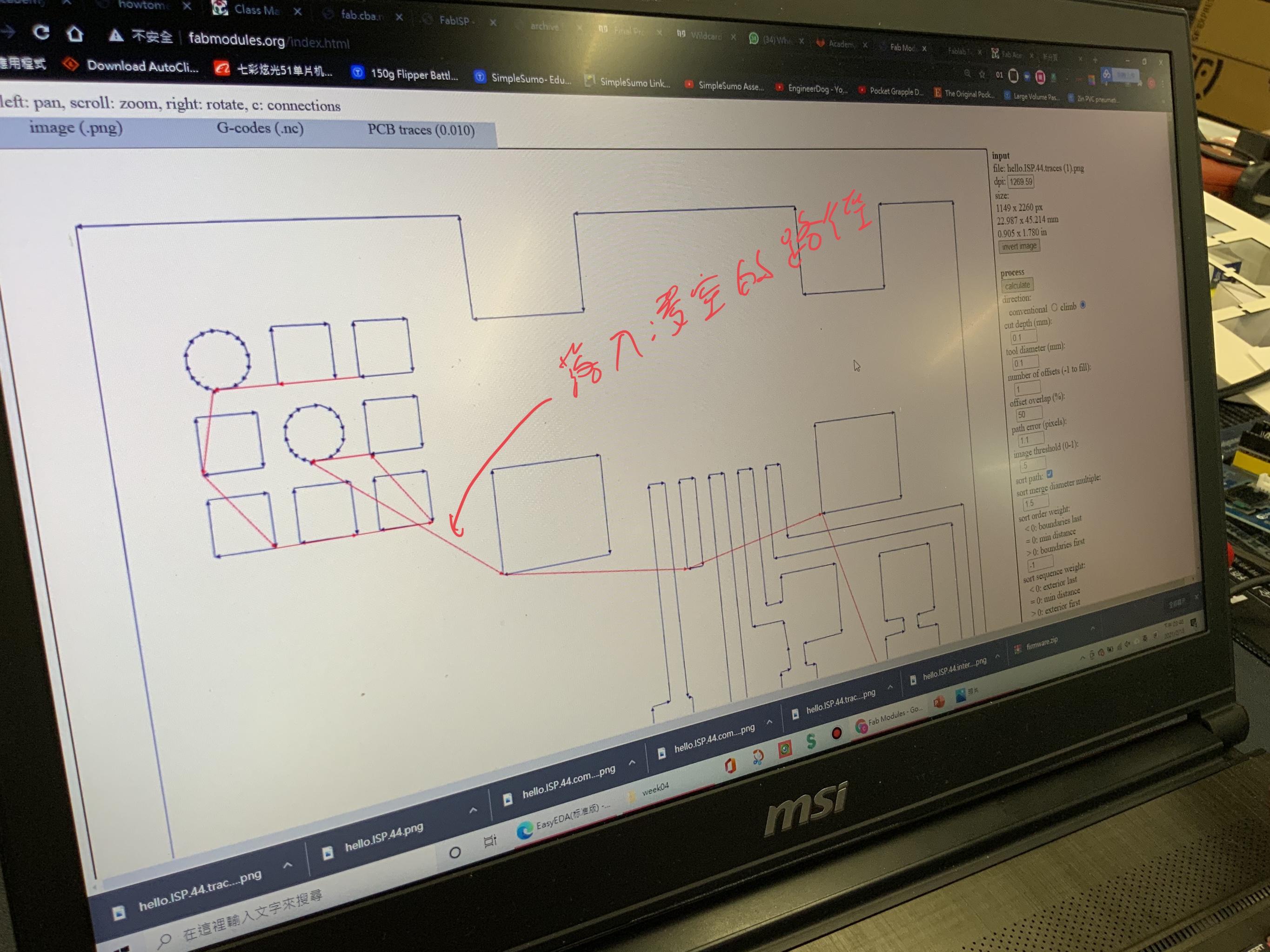
Step 5
In the below diagram, the red line mean that the Carving V-Bit will stay above from the PCB and it will move it to different location from the PCB.
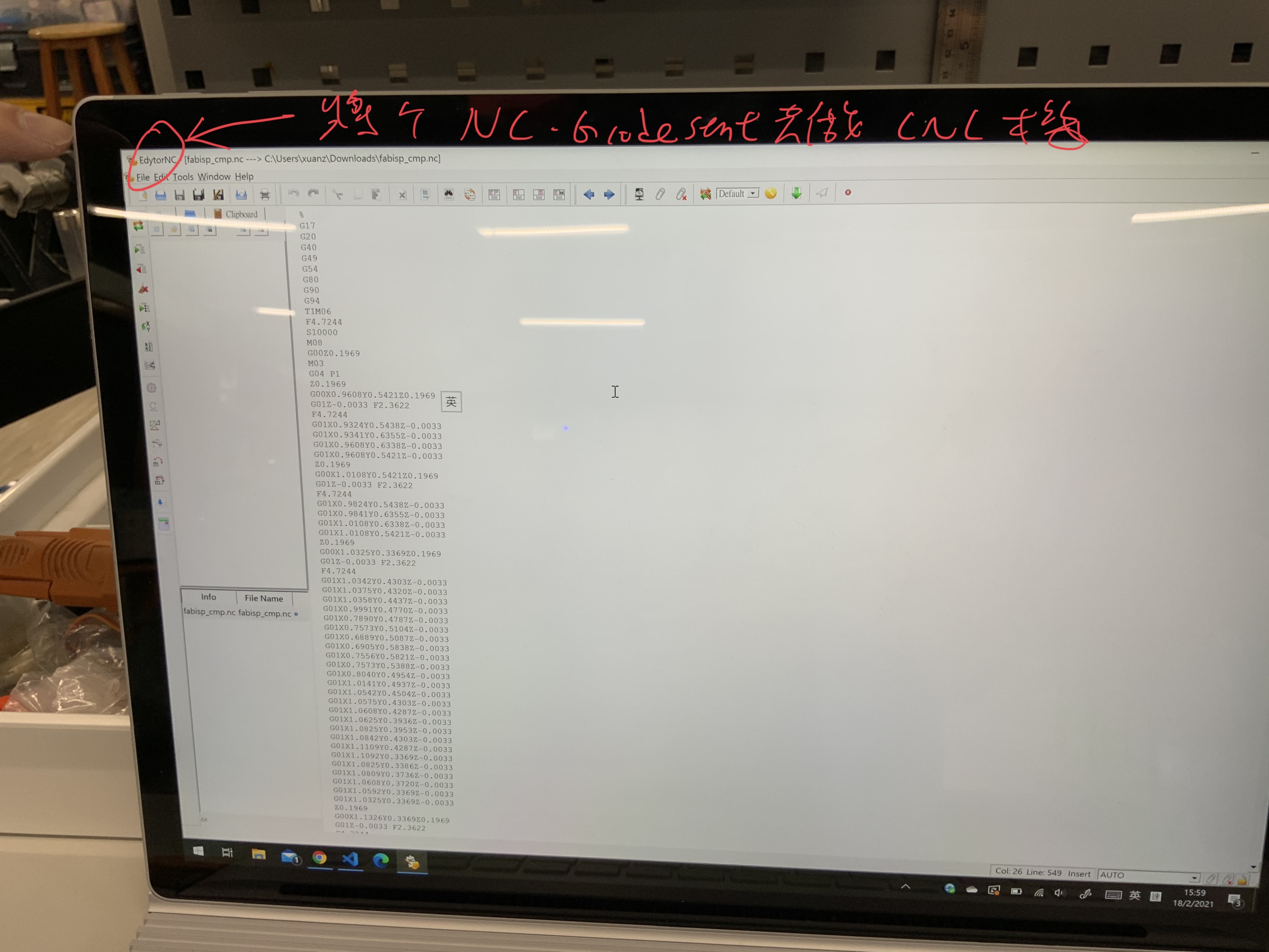
Step 6
After that, I need to move the G code to the milling machine. The software we used is called EdytoNC
G code is like a step by step commands in order to control the milling machine.
Step 7
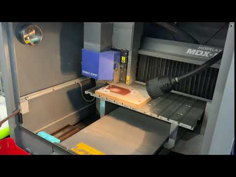
Please click above link to view this milling by clicking the above youtube link!
FR-1 for machine milling PCB Circuit board.
Material: FR-4 Glass Fiber, Copper Layers: Single-sided. Dimension: 125x75mm(L*W) Thickness : 1.5mm.
Step 8
Please click above link to view this cutting out the PCB by clicking the above youtube link!
Produce the In-Circuit by stuffing the PCB
Step 1
The milling process is complete.
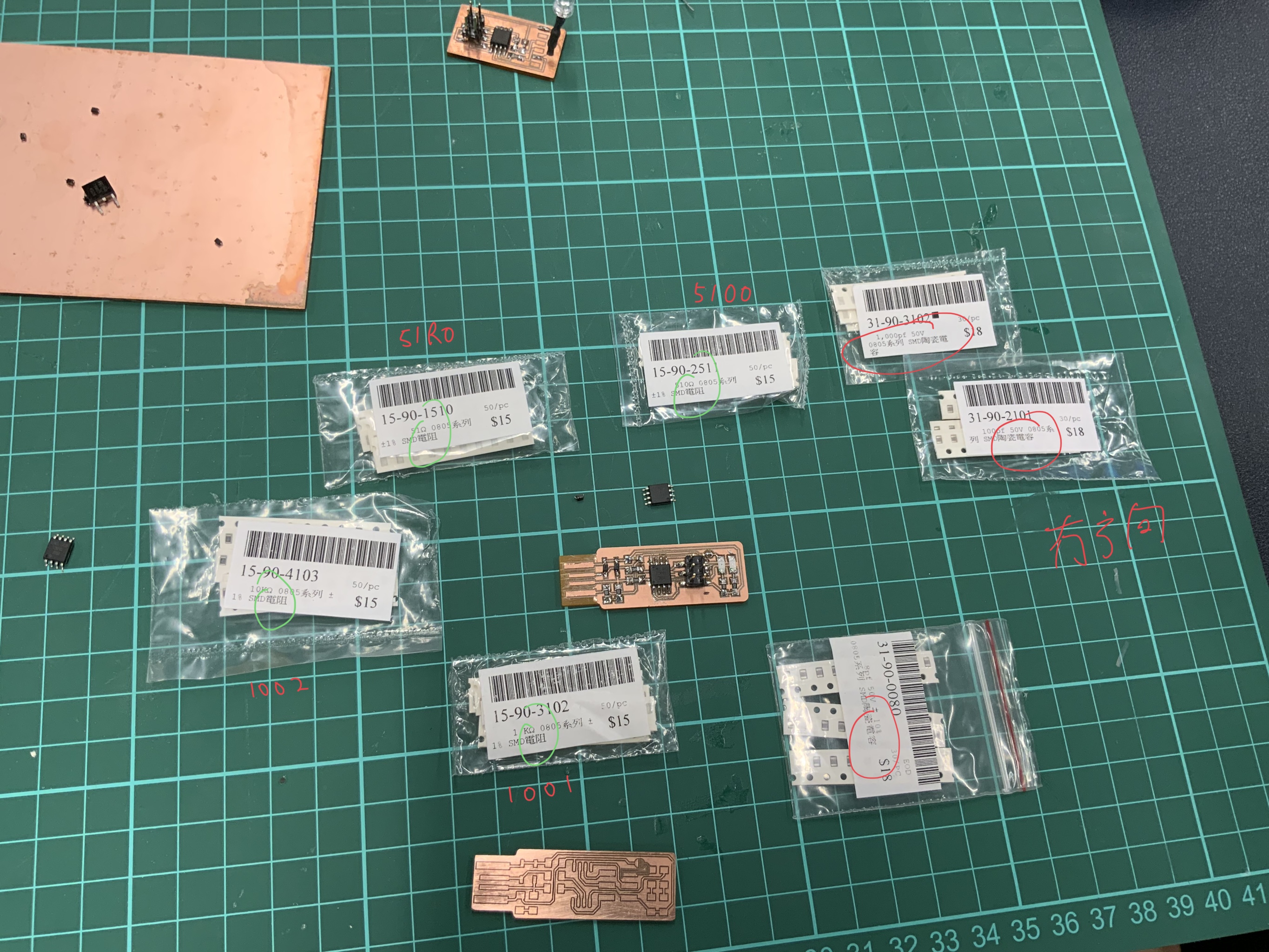
Also, the IC we used is called ATMEL Tiny85, and there are other resistors and capacitors in the in-circuit programmer.
Step 2
It is very difficult for me to stuffing the resistors and other components.
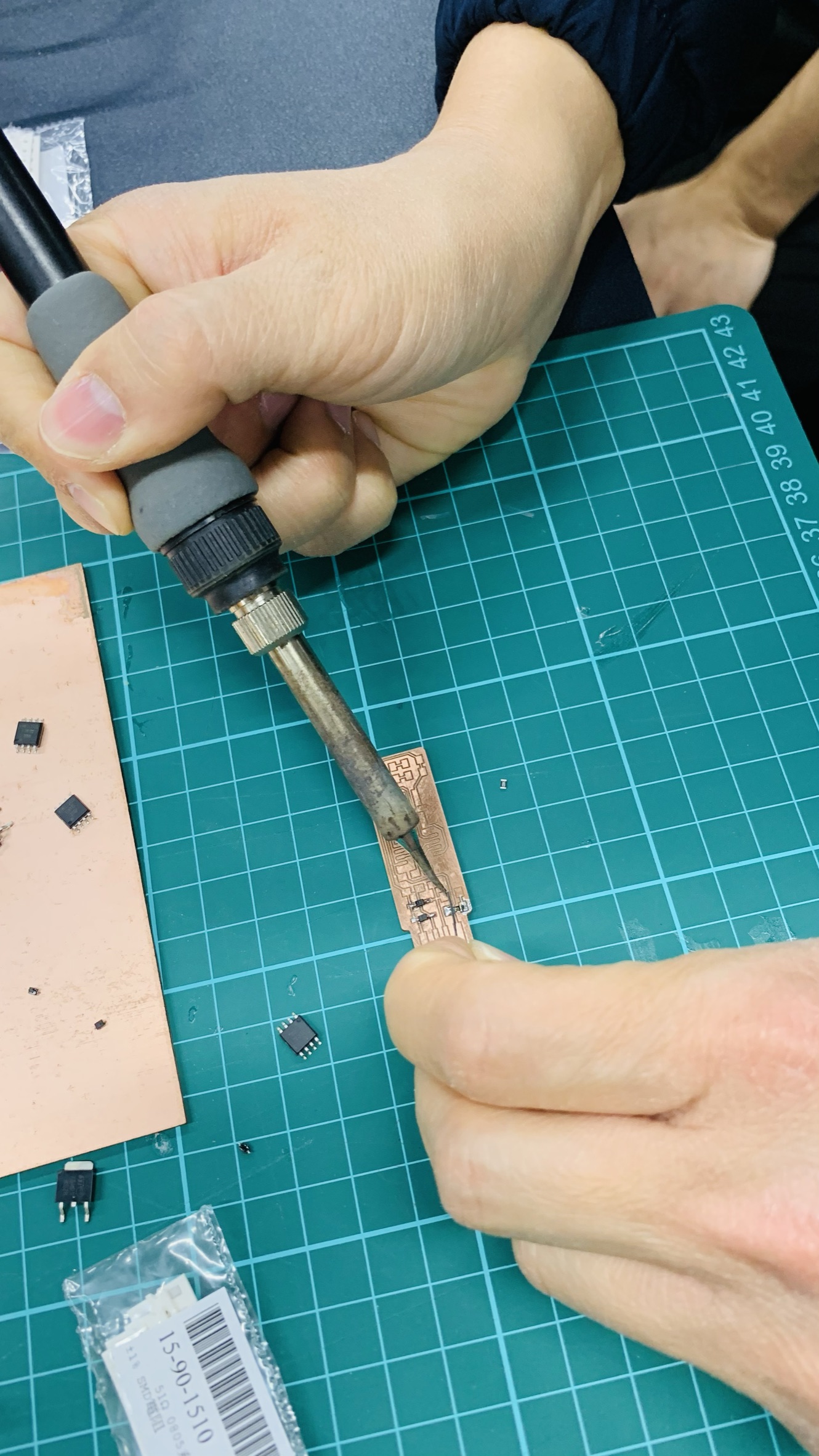
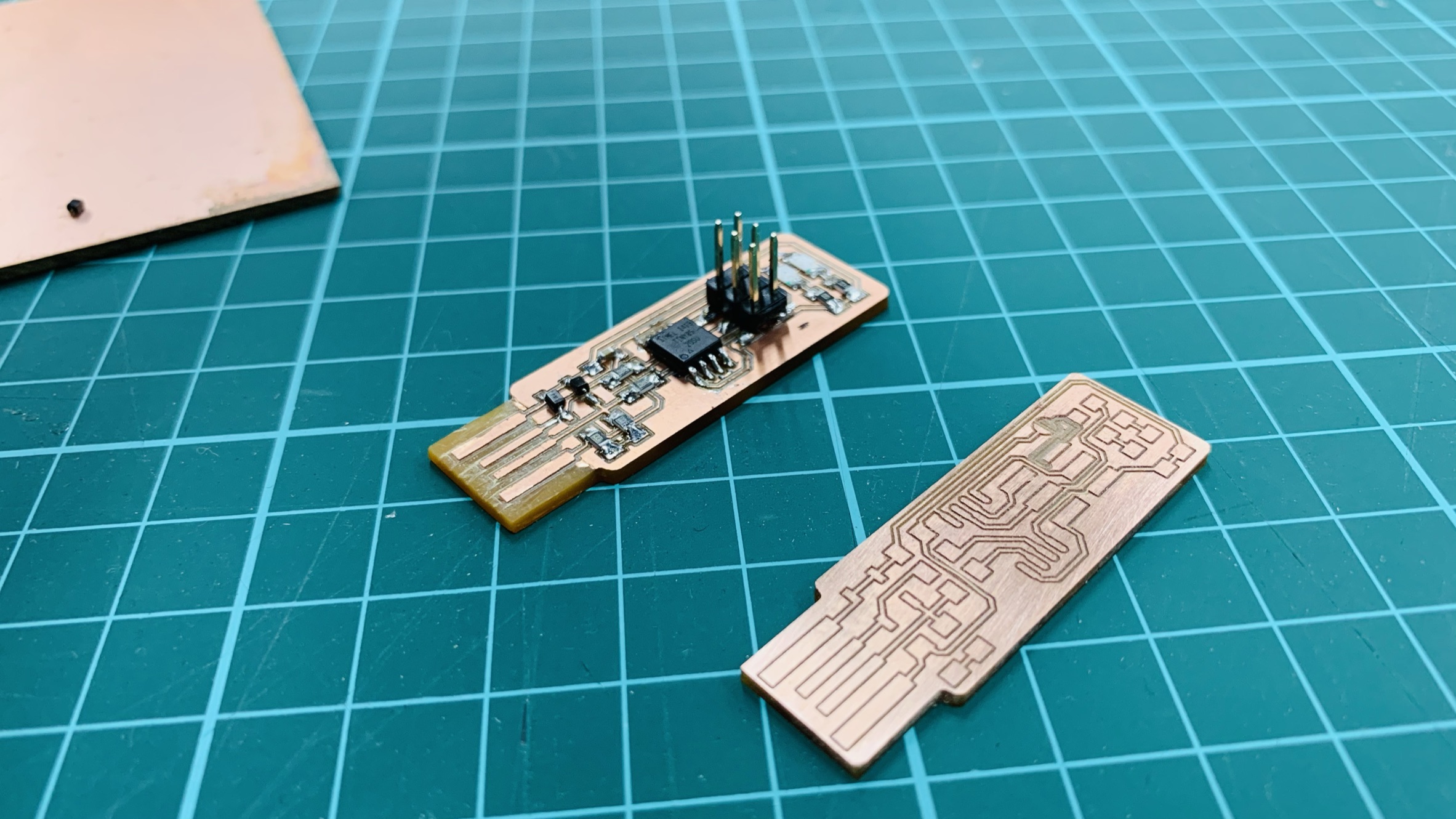
Step 3
This is the final product of the in circuit programmer
Testing the In circuit programmer
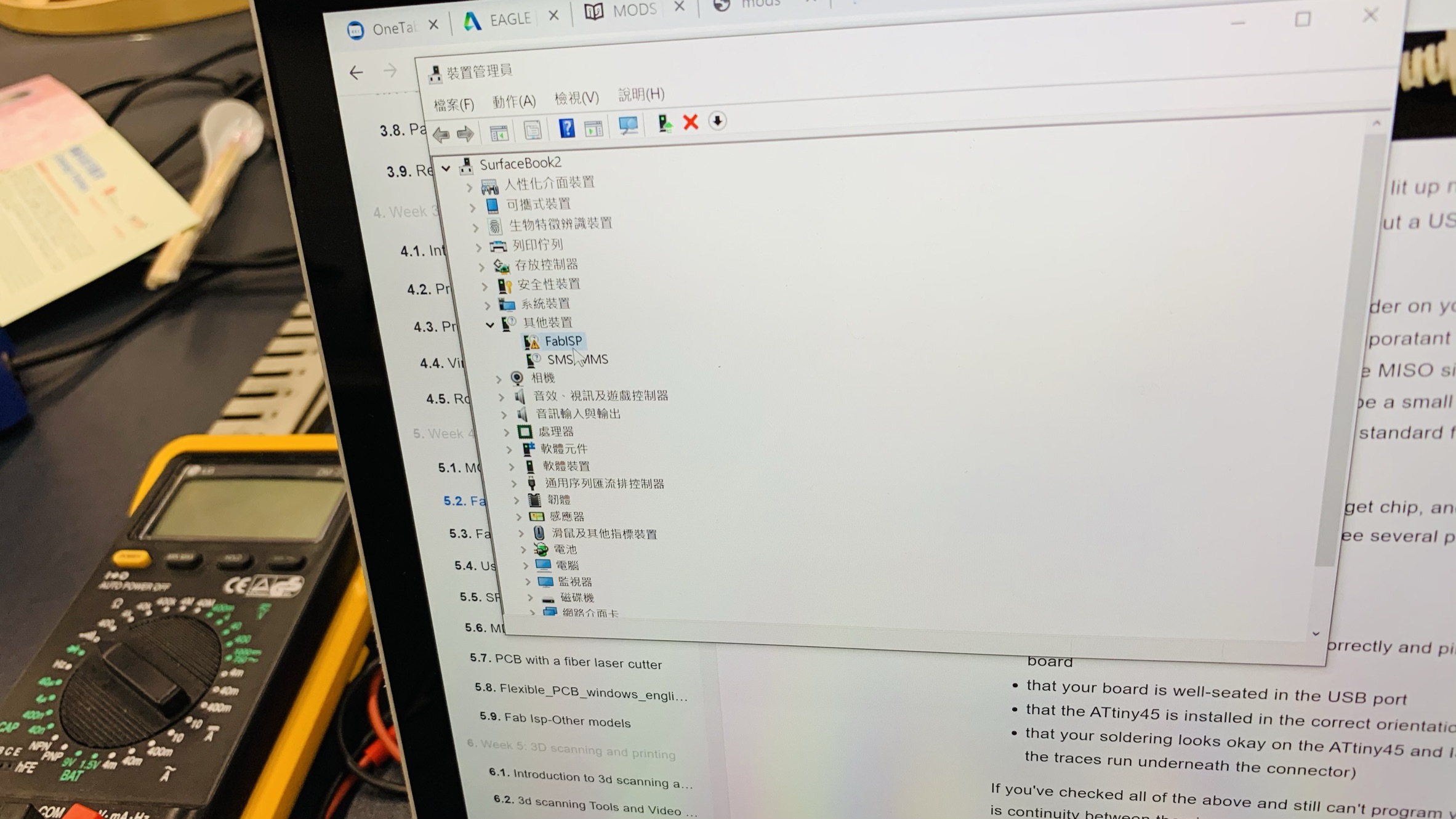
Step 1
In this device management, the operating system could detect the FabISP as the image below.
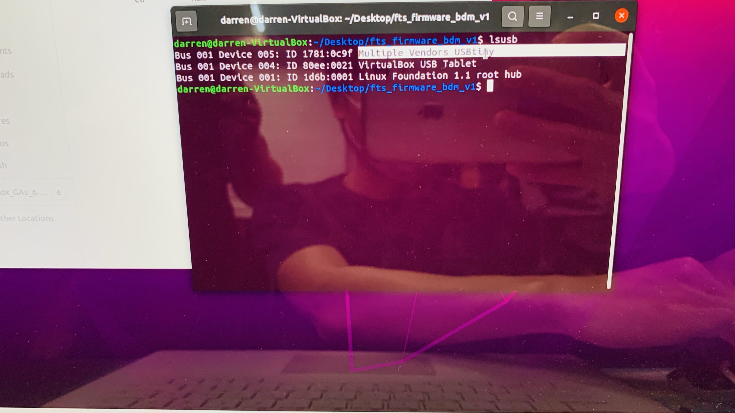
Step 2
In order to test the machine, we need to use a Linux operating system.
However, Window platform is not easy to test the in-circuit programmer.
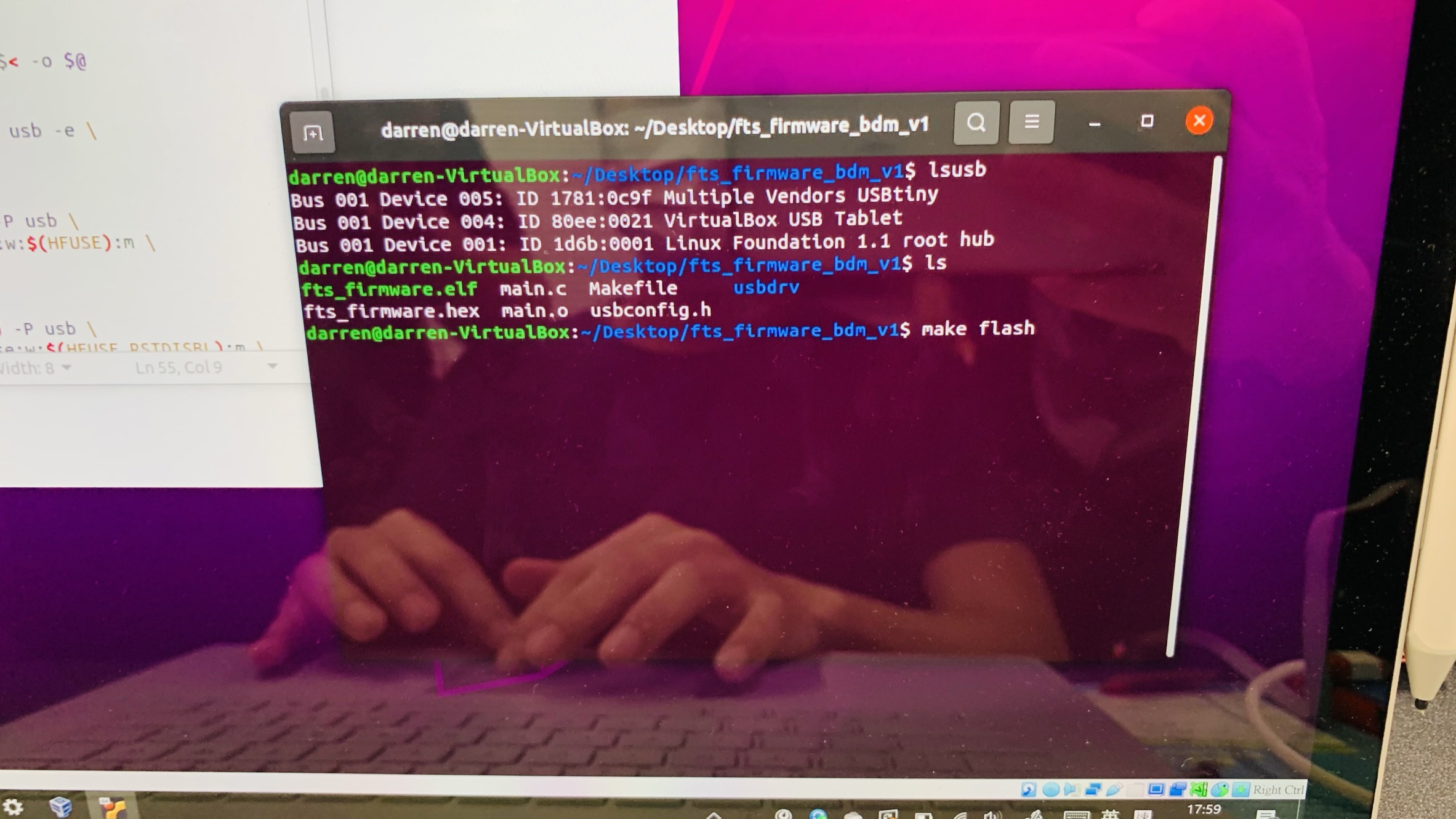
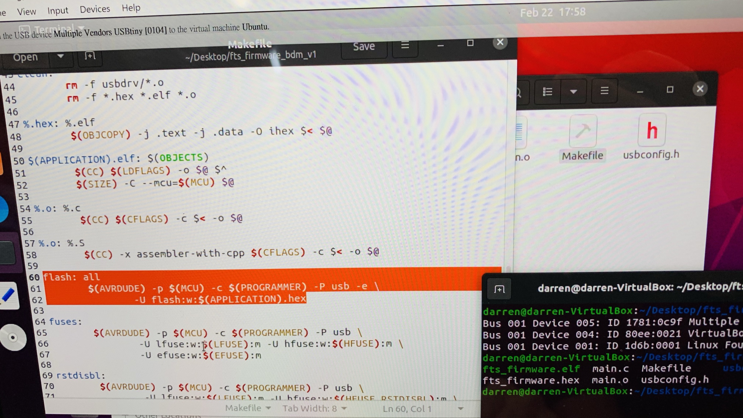
Step 3
In Linux, by clicking make flash, it prepare to write the program into the in-circuit programmer.
Step 4
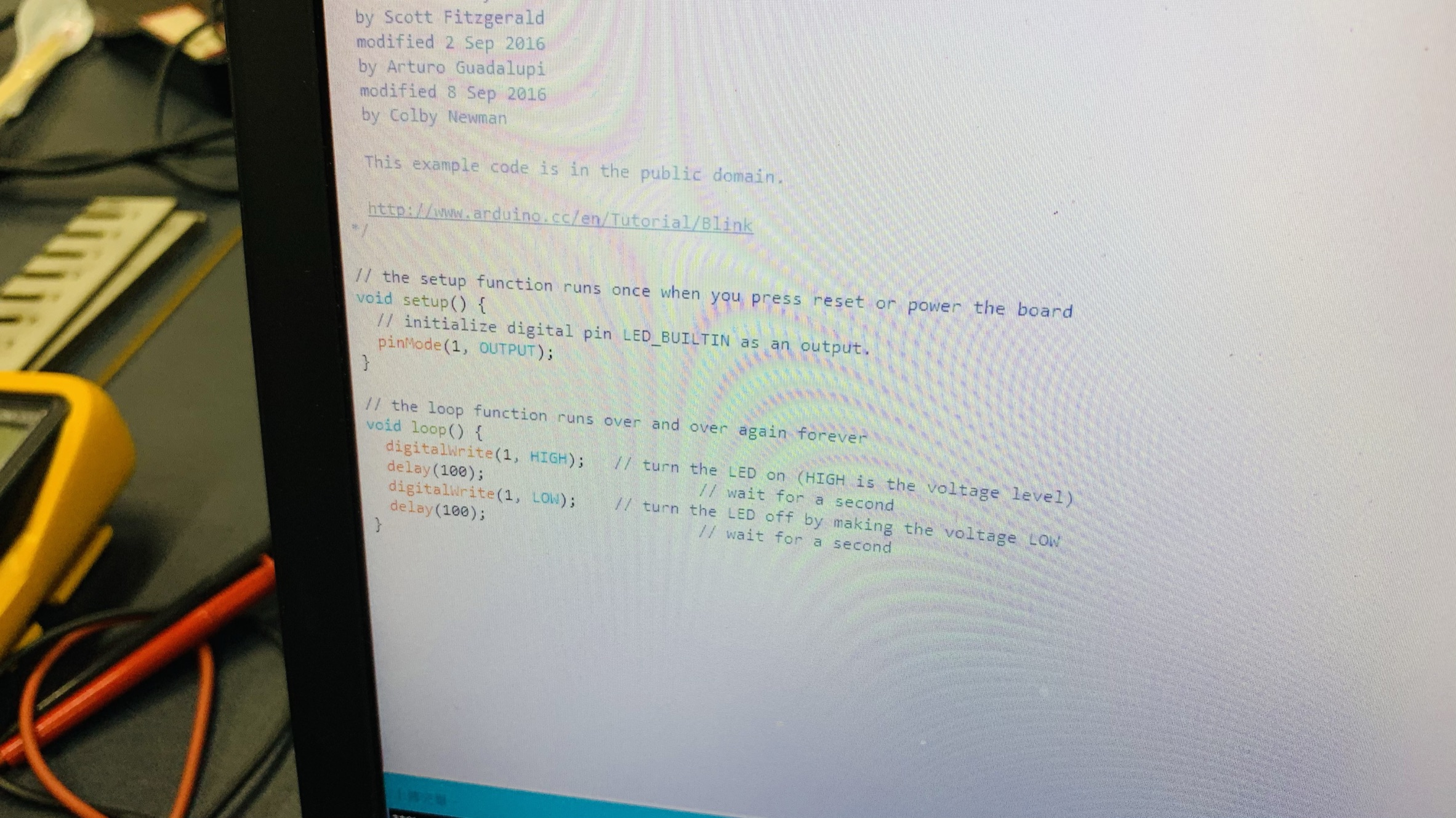
We used ardunio to write a testing program. the program is very simple, it just flashing the LED.
Step 5
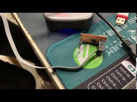
Please click above link to view this the testing result by clicking the above youtube link!
Group assignments
Here is the link of the group assignment .