7. Electronics Design
For this week, I have learnt on Electronics Design:
- EAGLE - Easily Applicable Graphical Layout Editor
- is a PCB CAD software
- Run on Windows, Mac, Linux
- Download to install for Making a PCB in minutes
- Low cost on design many types of PCBs
- Share the Design of Arduino Board or Component Placement Easily with Hobbyist Community
- EAGLE Workflow
- Design circuit in a Schematic Editor
- Place Components in Board Layout Editor
- Route Traces by Manually or with Autorouter
For this week, I have worked on:
Group Assignment:
We have used the test equipment in our lab to observe the operation of a microcontroller circuit board including checking operating voltage on the board with multimeter or voltmeter and using oscilloscope to check noise of operating voltage and interpret a data signal. If you have interest, you can CLICK HERE to know more about the details. Some main points are mentioned below.
- Use the Test Equipment
- Microcontroller Circuit Board
- Digital Multimeter - Model DT830B or ANENG AN8001
-
Oserve the Operation of a Microcontroller Circuit Board. Microcontroller is also called Single-Chip Microcomputer
-
Check Operating Voltage on the Board with [Digital Multimeter - Model DT-830B
-
Use Oscilloscope to Check Noise of Operating Voltage
-
Use Oscilloscope to Interpret a Data Signal
Individual assignment:
MAKE MY OWN FISH-SHAPED PCB
Step 1
Download and Install a PCB Design Software for Everyone - Eagle

Step 2
Download and Install the fab.lbr

This library consists of different components what you needed. Add any necessary component after the installation of this library including adding a button and a LED this time.
Step 3 Download and Open the helloEcho Schematic for “echo.ftdi.44”
“echo.ftdi.44” is one of the Drawings Representing a Circuit in Electronics.

Step 4
Edit this Echo Hello-world Board
I used many different basic Commands including “add”, “move”, “value”, “name”, “label”, “net”, “delete”, “copy”, “route” and so on for editting.
- Add a LED with Current Limiting Resistor and a Button as the example
add = opens up the libraries so that you can add components in Schematic view


- Connect all Components with a Wire that made sure the circuit was completed
net = makes a logical connection

- Name, Label and Value all Components for Easy Recognition
name = names a component

label = displays the name of a component in schematic view

value = used in Layout view, this tells you if you need to add a connection (follow yellow lines)

delete

A LED with current-limiting resistor, which was the output device, was added.
A button with 10k ohm pull-up resistor, which was the input device, was added.
Turn from Schematic View to Board Layout View

Step 5
Design Rule Check
I check the 1/64 endmill that is able to go between all traces in order to cut the board successfully by the CNC milling machine. It should display a “no error” message in the bottom left hand corner of the screen.
Step 6 Redraw this Echo Hello-World Board - The example of design with own style during the lecture was very eye-catching and attracting for me to design my own PCB as my first drawing in final project.
- I used Fusion 360 to draw 3D PCB based on my 2D drawing liked as a fish shape.

- Using Fusion 360 to draw 3D PCB was recommended because each version of saved files or stages was shown for you to go back and change each version easily.

- I clicked on each shown line and then inserted Spline Fit Points as appropriate place in order to draw the figure more smoothly.

-
When 3D PCB drawing from Fusion 360 was ready, Eagle was used again to turn the Schematic View (SCH) to Board View (BRD)
-
The “FUSION 360” at the right hand side of the screen of Eagle was pressed and I chose “Link to an existing Fusion 360 design”. Pressing Next and opening the saved file for ready 3D PCB drawing were essential before pulling from Fusion to sync my changes.
Step 7
Move all components within the Fish-shaped PCB
-
At first, Unfortunately, 50mm-length of the shape was not enough to put all the components on it. Therefore, I should go back to the 3D drawing in Fusion 360 and enlarge the size to 100mm-length. An then pulling the new files from Fusion to sync my changes.
-
All components were put on larger size of fish-shaped PCB.
-
I can rotate the components by right clicking of the mouse.
Step 8 Route Traces on Board - Each individual component was moved and every trace was routed
- Autorouter feature is good for making a general layout with 100% satisfaction (TopRouter)


- The latest design for Eagle design was pushed back to Fusion 360 to check the layout of designed PCB in 3-dimension if you want to further develop and design such as addition of enclosure for PCB.
Step 9
Export Image
I can show/hide the layers by clicking on display.
1000 dpi resolution was used to change from dxf to generate G-code for CNC Milling.
Step 10
Make the Echo Hello-World Board
- Milling
Stick the copper board onto the flattened plane of the wooden board and Set the origin and appropriate XY-axis for the copper board

Start milling

Removing the residue from the PCB board by vacuum cleaner

The 1000 dpi setting of the image was correct but I still obtained failure PCB because the Fish-shaped of PCB outline was designed in double-sized.

After decreasing the size of the fish-shaped size, the problem was solved.

- Soldering
All the components should be put on PCB by soldering.
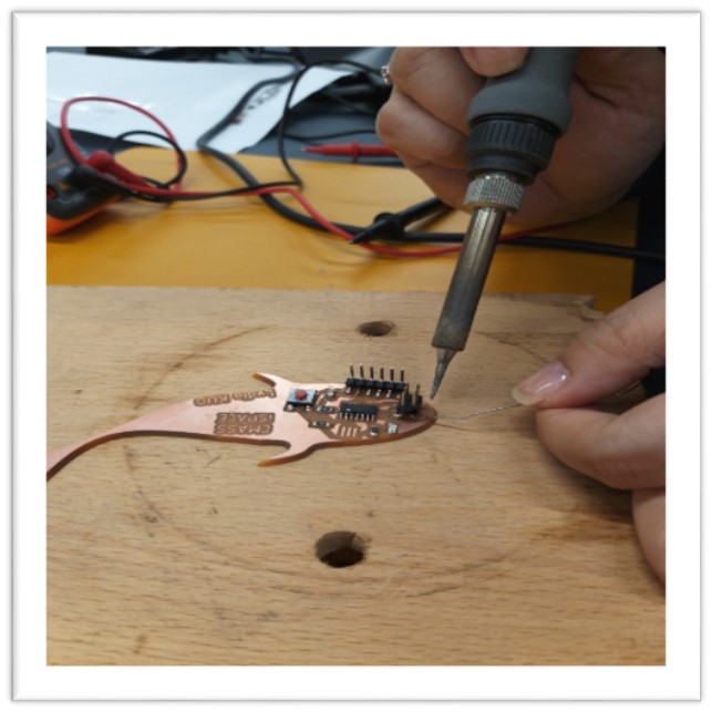
According to the techniques in Tin wire for soldering in week 5, from my experience, I spent too much time for soldering one component on PCB.
Therefore, I decided to mix with another technique to fix all components by using lead-free solder paste. This paste, which contains the alloy of Tin(Sn) and Bismuth(Bi) and are less toxic elements, was pressed bite by bite by using syringe. This method was more easily handled.
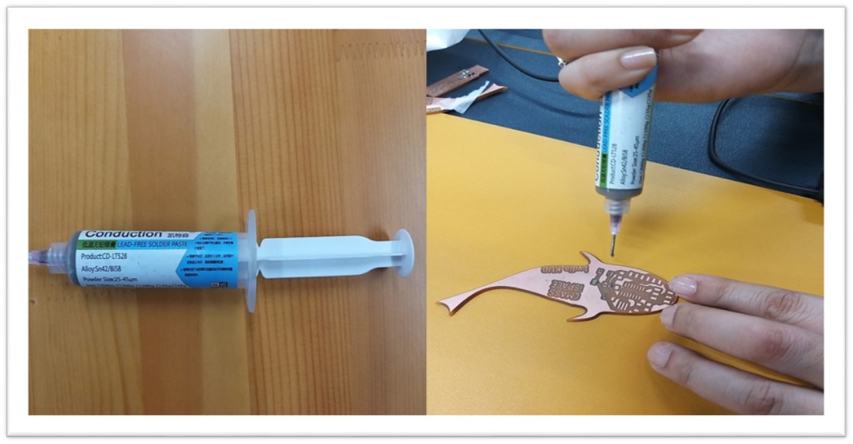
This solder paste contains Flux which is nearly inert at room temperature but becomes strongly reducing when its temperature is increased. This prevents the formation of metal oxides on both the base and filler materials to which it is applied. It also prevents the beading of the applied solder, facilitating easy flows and application.
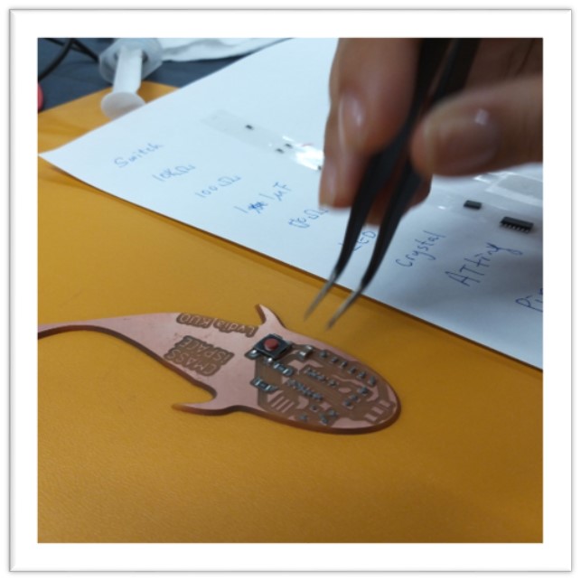
All Components were shown here for this Soldering.

One of the components, switch, was put onto the PCB by using forceps.
Heat gun was used to melt lead-free solder paste.
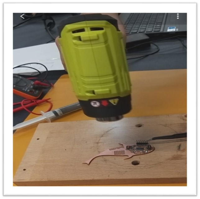
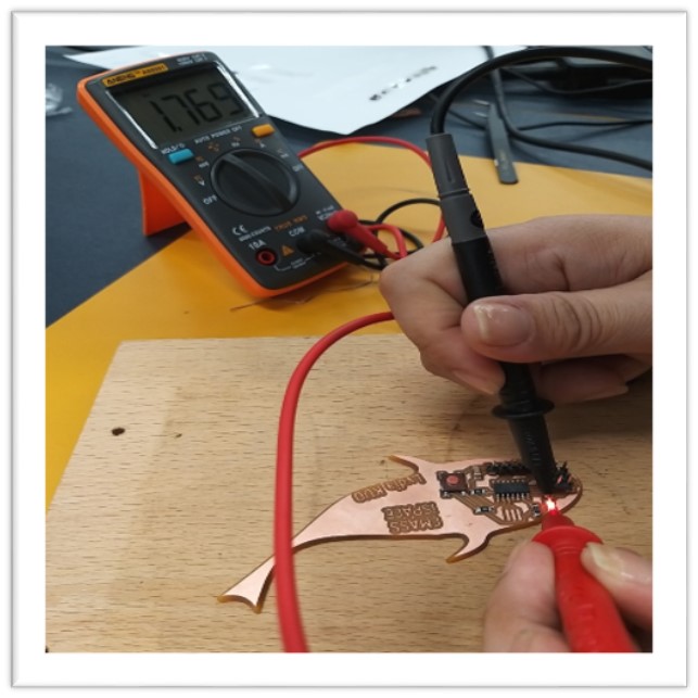
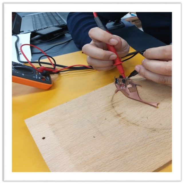
When I use the multimeter to measure the voltage in the circuit which was whether completed or not. I have found that there was no any voltage which was across the LED. This might be caused by too hot from the heat gun for breaking the LED which was sensitive to high temperature. After removing the broken LED and replacing a new one, the new LED was lighted this time.
This technique of using solder paste is only used in surface mount only.

Soldering Iron (red area) vs Syringe with Solder Paste (blue area)

- Debugging
External crystal was out of stock right at this moment. Therefore, I decided to use the internal crystal instead of it. The circuit was still worked because this circuit did not involove high-speed inter-board communication. The time of flashing bit was not critical for this circuit design.
Step 11
Test the Echo Hello-World Board
Connect the PCB together with the ISP and computer

Connect the USBtiny for the Windows device management

The program for testing was as follows:
Press the button, then blink. If release the button, LED turn off.

Step 12
Getting the better PCB
Thanks for all of the opinions from the instructors and my colleagues, I try once all the steps once again, I get more appropriate PCB.
Source File for Fi sh PCB(FUSION360)
Source File for Fish PCB(TEST)

Tell me and I forget.
Teach me and I remember.
Involve me and I learn.
~Benjamin Franklin~