7. Electronics Design
Installing EDA tools and libraries
I’ll be using the KiCAD. Version 6 was recently released. From what I’ve seen so far it’s a huge improvement on previous versions. Thankfully there is support for the M1 architecture Mac
First step: download and install.
I love that we can download from CERN, and that they’re a major contributor. It comes supplied as a standard disk image. In Applications, I renamed my old kicad folder in kicad5 and copied in the new kicad and the demos.
Second step: Picking up the Fab Academy KiCAD libraries. We clone the from the repository so that we can keep them up to date as they improve.
> git clone git@gitlab.fabcloud.org:pub/libraries/electronics/kicad.git
Cloning into 'kicad'...
Enter passphrase for key '/Users/ees609/.ssh/id_ed25519':
remote: Enumerating objects: 1364, done.
remote: Counting objects: 100% (26/26), done.
remote: Compressing objects: 100% (26/26), done.
remote: Total 1364 (delta 11), reused 0 (delta 0), pack-reused 1338
Receiving objects: 100% (1364/1364), 1.55 MiB | 2.29 MiB/s, done.
Resolving deltas: 100% (996/996), done.
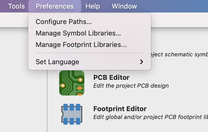
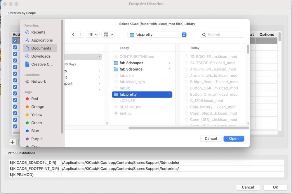
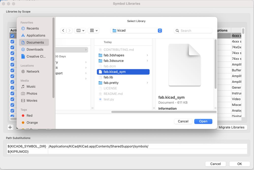
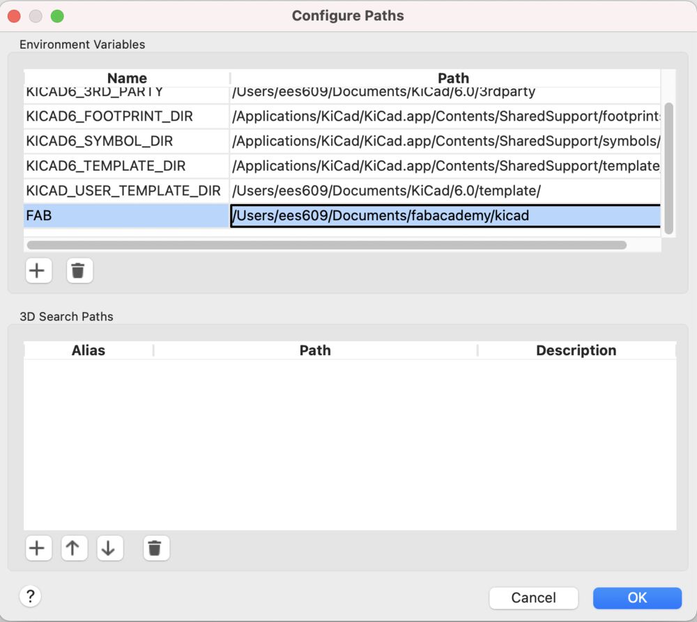
Once we have the library locally we have a three step install in Kicad adding the symbols, footprints and making the 3D models available, all according to the instructions on the gitlab page of the library.
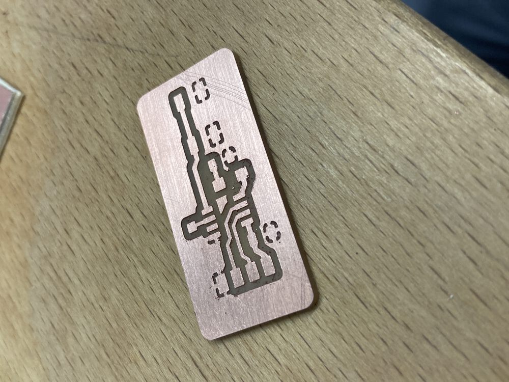
What are we making?
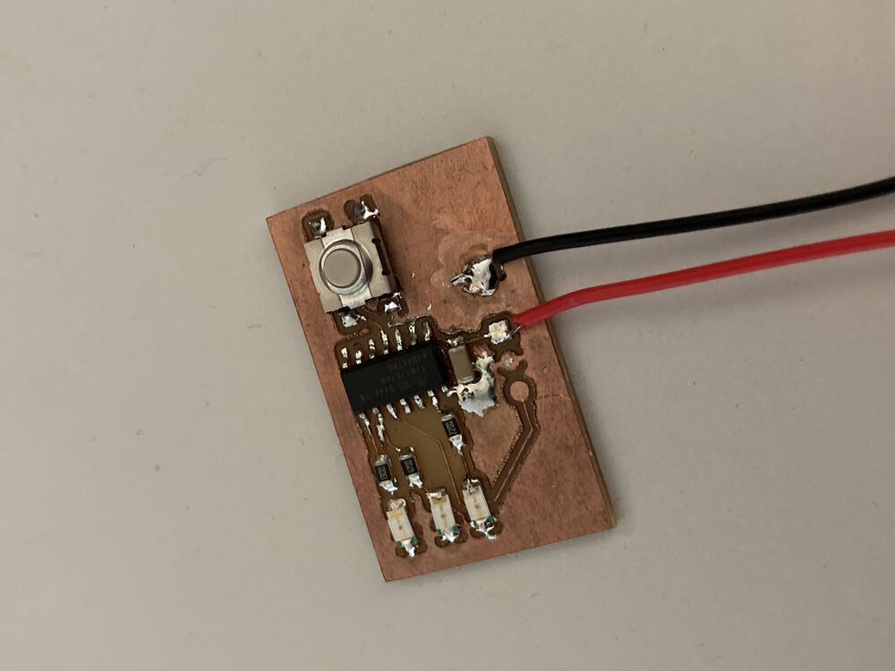
This is written out of sequence due to COVID. The board that was used to complete the work this week was manufactured for Networking week
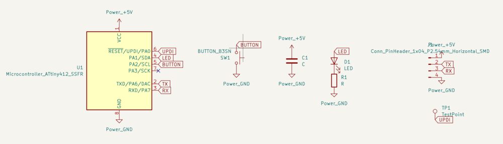
The board makes use of the ATTINY412, an LED with current limiting resistor and a button. The serial is broken out to share a header pin connection with the power coming in. A single test point is used to flash the device over UPDI.
Designing the circuit
First off work out what our foundation is. For this I like to make use of the documentation for the megaTinyCore, even if we don’t plan to use the Arduino environment, the diagrams are a great way to get a handle on the peripherals.
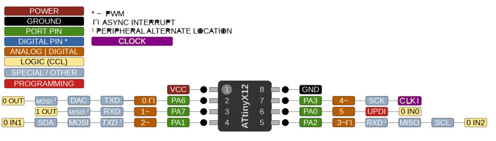
So it is all as we might expect, the TX RX are connected to the serial peripheral on pins 2 and 3. UDPI is on pin 6. Supply and ground on 1 and 8.
We’ll add a bypass capacitor close to those supply pins.
We’ll add the button to pin 4 which has an asynchronous interrupt available. (Probably no use it in the first instance but good to know we can upgrade from polling if we want to).
We’ll add the LED to pin 4 where we have PWM available.
Always read the brief
I had a go at this last year, and missed the echo component!
Let’s try again…
Schematic Capture
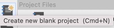
Start off by starting a new project:
Once we have a project we’ll be presented with both an empty schematic and PCB. Open the schematic design tool. There are a series of tools that we need to draft our circuit. They are named well and have sensible short-cuts that are easy to learn.
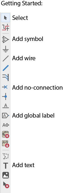
Fundamentally we want to add symbols representing the components of our parts, place and wire them together. We can tidy things up so that there’s not a lot of crossing wires by using global labels.
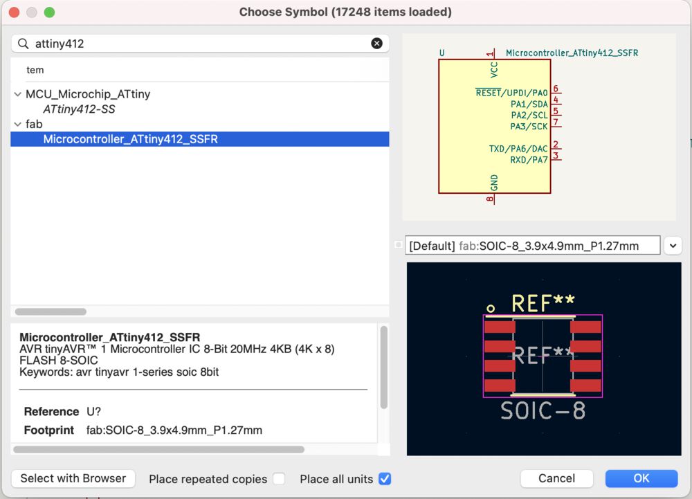
Adding a symbol, we see that our ‘fab’ library has been picked up.
It doesn’t take a long time before we have a simple circuit captured:
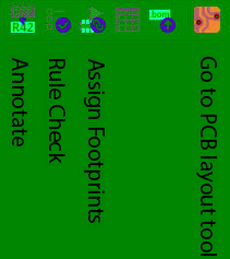
Once we have the parts placed and joined up we can run through the tools in the top menu bar:
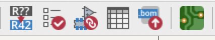
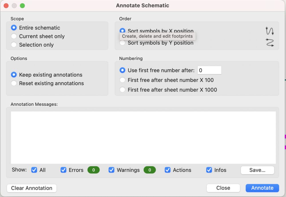
Replace the generic part annotations, C?, U?, J?, by hitting the annotate button all parts will be sequentially numbered.
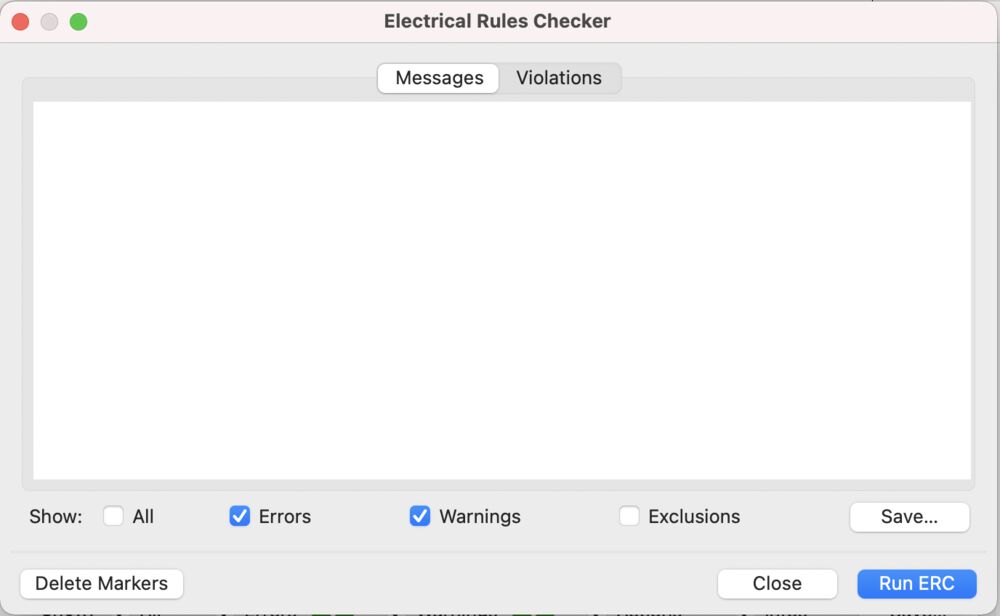
We can run an Electrical Rule Check.
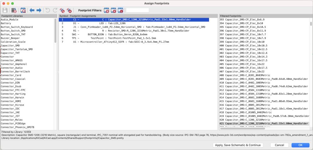
We can then start to assign footprints to each of our parts.
We can move on to PCB layout.
PCB layout
Over the last two years I’ve designed a few boards. So the description of the tools below does include a couple of images from a different design where I captured the appropriate screenshot.
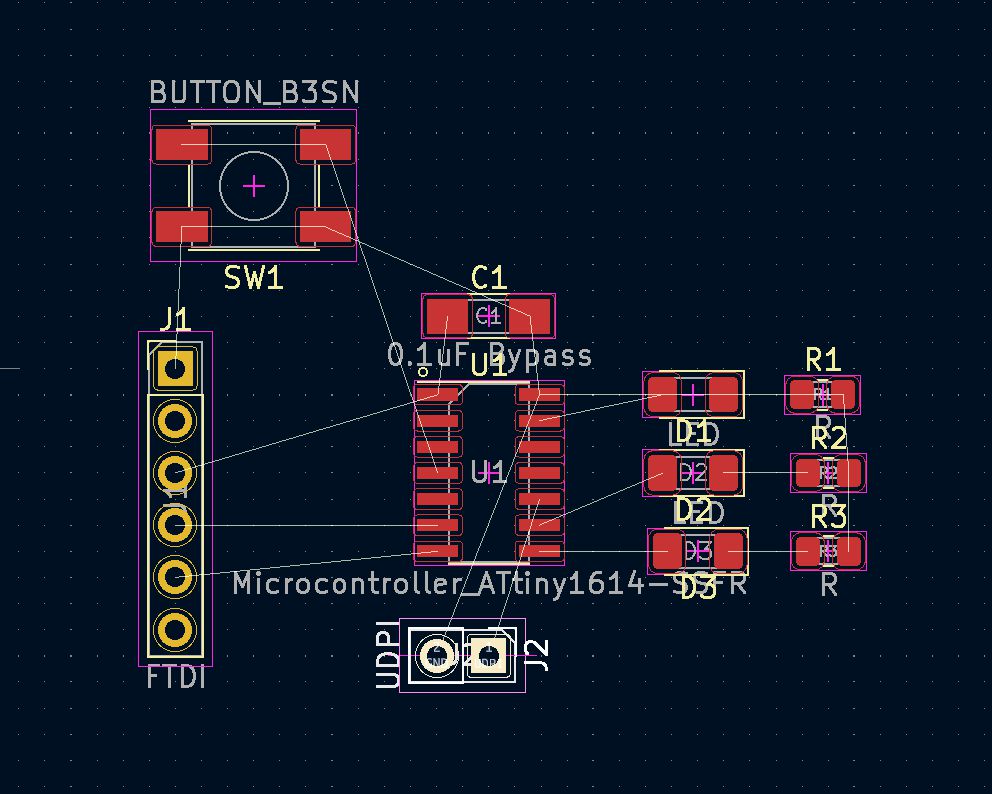
We start off with importing the rats nest. A jumble of parts with logical connections showing.
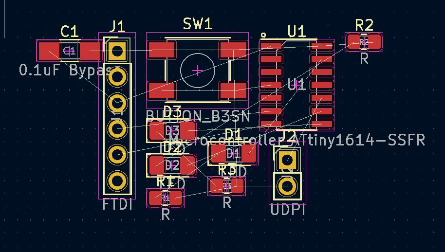
Highlighting with the mouse and hitting ‘m’ for move and ‘r’ for rotate lets us start to tease out the jumble until we have an organised layout.
We can then start wiring. Replacing the logical connections indicated with the simple white lines, with tracks. Starting from a pad will highlight the potential destinations for the connection.
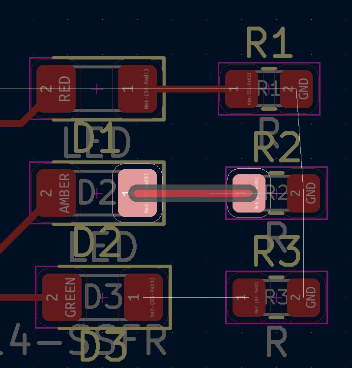
Repeat until we have everything but the grounds wired.
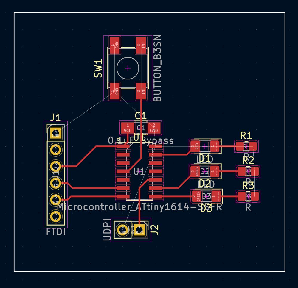
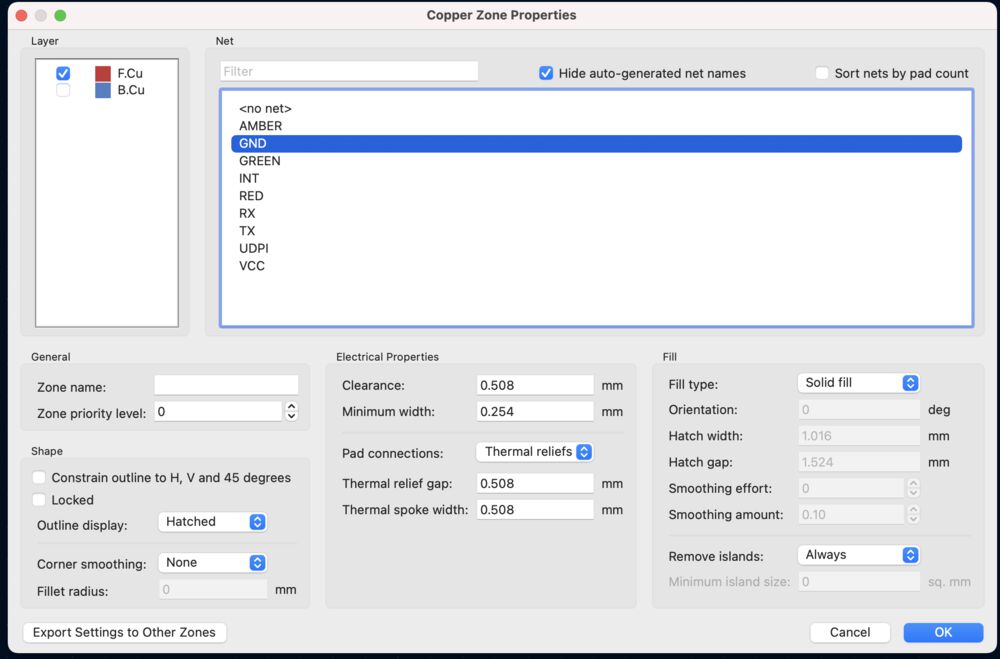
To connect all the grounds we’ll try a copper flood. On the first click you get a dialogue, select the ‘net’ that we want to attach a fill zone to. Once you complete the dialogue you’ll be returned to the layout where you can continue to click and outline the zone.
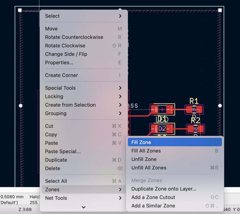
Right click on the apparently empty zone to find the ‘Fill zone’ command.
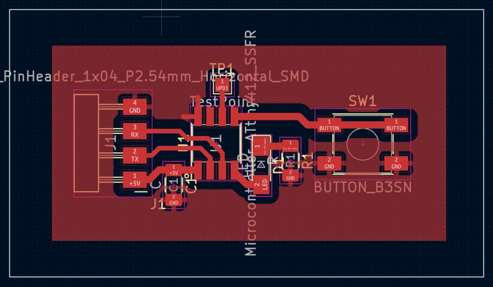
Resulting in a complete layout, this time illustrated with our echo board:
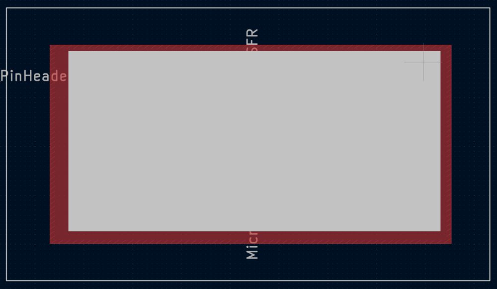
Next steps are to export files for manufacture. We need to make a couple of additions to our layout. For the method that I’ve worked out as being relatively reliable for isolation milling. In the Edge Cuts layer I put a frame around the circuit to limit the scope of the export, then in the User Drawing layer I add a rectangle to define the finished board outline.
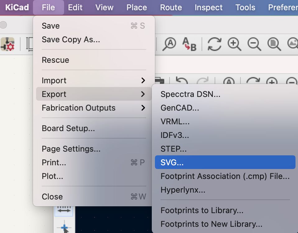
Export
Rather than use the raw plots option I use the Export as SVG, solely for the ‘Board area only’ radio button. You may need to also set ‘Black and White’ and uncheck ‘Print board edges on all pages’.
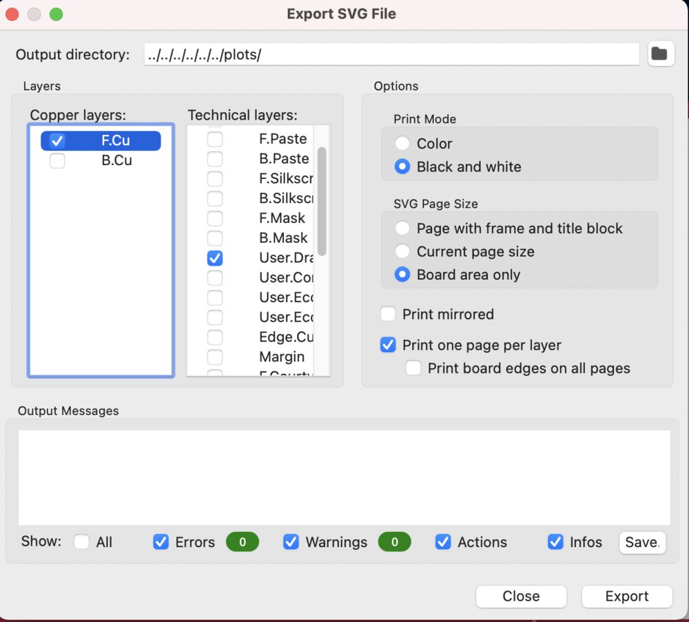
I’ll only export F_Cu and User.Drawing layers.
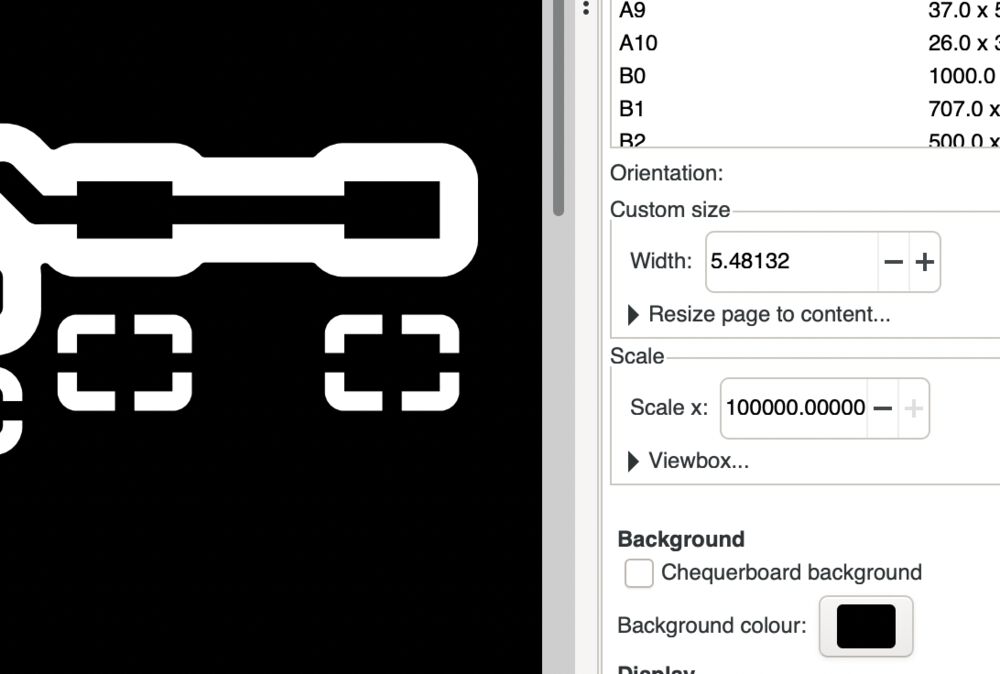
Inkscape
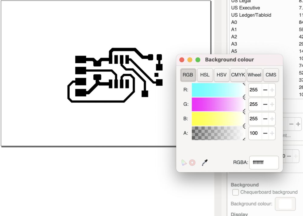
The resulting svg files are opened in Inkscape. I set the background of the images to match the tracks or copper fill so that there are no transparencies in the final images. In an image with a copper fill I’ll put in a white rectangle behind the tracks or they’ll disappear as the gaps are not there…
So in: File > Document Properties… you’ll find Background settings:
For the outlines image derived from User.Drawing, remembering that we need to set the background to white so that we don’t have issues in modsproject with transparencies. Using the original rectangle as reference I redraw it as a rectangle with the corners dragged round using the node tool.


Final step is to export as png, ensuring that you have the ‘page’ button selected and resolution set to 1000dpi
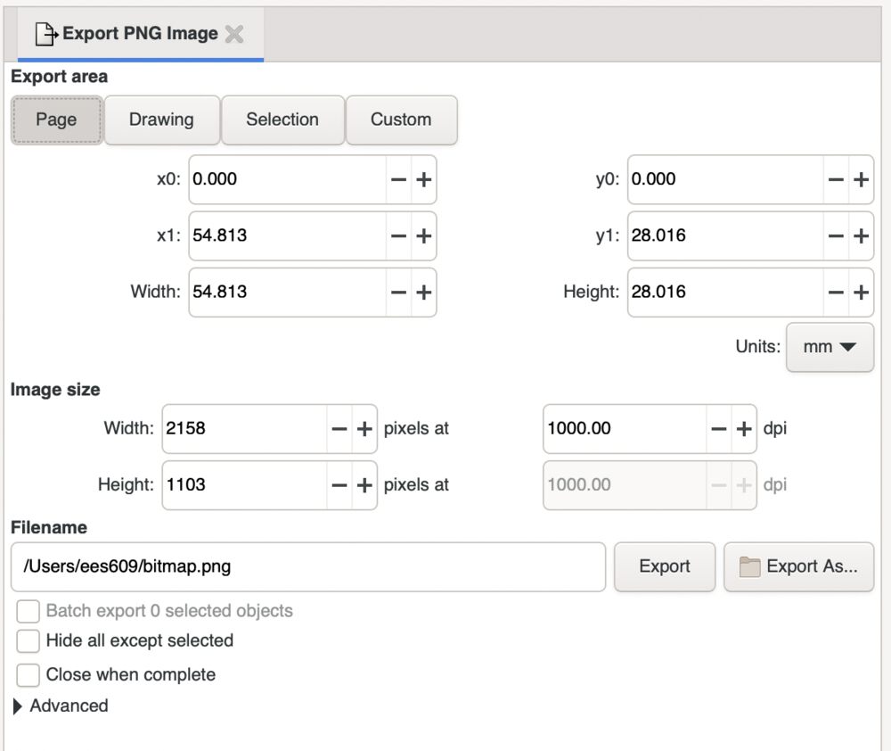
The final files ready for manufacture


These files are out through modsproject and manufactured using the SRM-20 as described in Electronics Production
Issue
For an issue we had in manufacturing boards see Networking week #outlines with curves
Source files
Hero Video
Here we can see the board acting as the Controller in Networking and Communication
The software was loaded using the Arduino and a UDPI programmer. See Embedded Programming
Group work
No group page to link to.
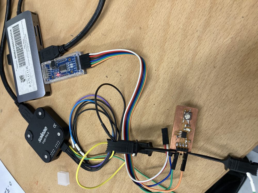
For a contribution to group work I took a look at the echo board that we just manufactured. Using a Saelae Logic Pro to look at the serial connection and supply. The board is being powered by the FTDI cable. It has the Networking firmware installed. This makes it the control node of a small network, see video above.
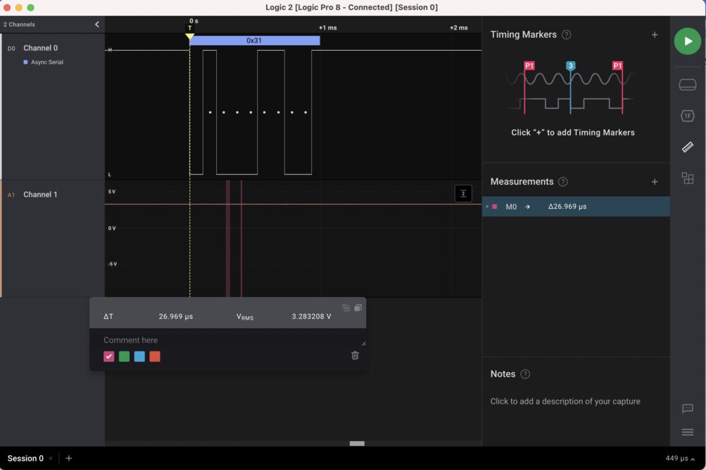
In the first instance we powered up the board and pressed the button. The logic is set to trigger on a falling edge on channel 0, with channel one set to analog. We captured a serial signal of 0x30. Hexadecimal for the expected message of ‘0’ sent from the control node to the peripheral nodes. In this case addressing node ‘0’. We can see that the FTDI cable is supplying close to 4.9V. We have some small losses from the native USB 5V.
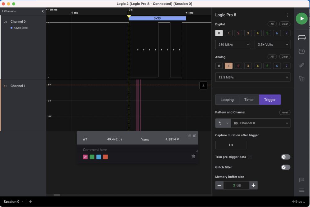
In our second observation we set the output of the FTDI cable to the 3V setting and interacted with the board so that is was sending out a message of ‘1’. We see in the capture 0x31 and 3.3V.