11. Output Devices
This week working on adding an output to a circuit. Can we also do something that will cover input week?
For my final project one of the components that I need to control is a fan. I did a bit of reading about motor control and concluded that a simple PWM was the best fit. As I want my interface to be analogue and I want my system to be a ‘kit of parts’, I decided that it was a good opportunity to implement the complete fan controller. So the board will have the following:
- Power regulation
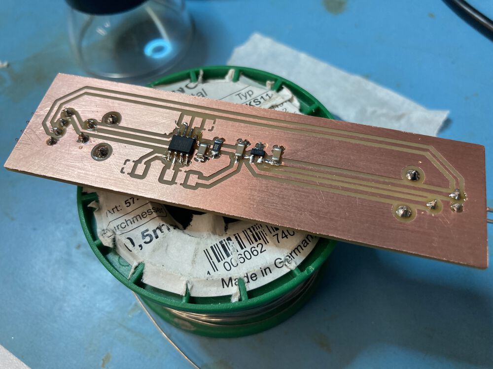
- Attiny412
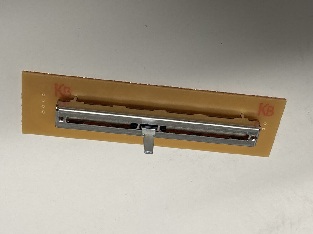
- Slide Potentiometer
- UDPI
- Serial
- (spare pin broken out for future expansion)
Files
See Electronics Design week for more detail on the EDA tools used.
Measuring
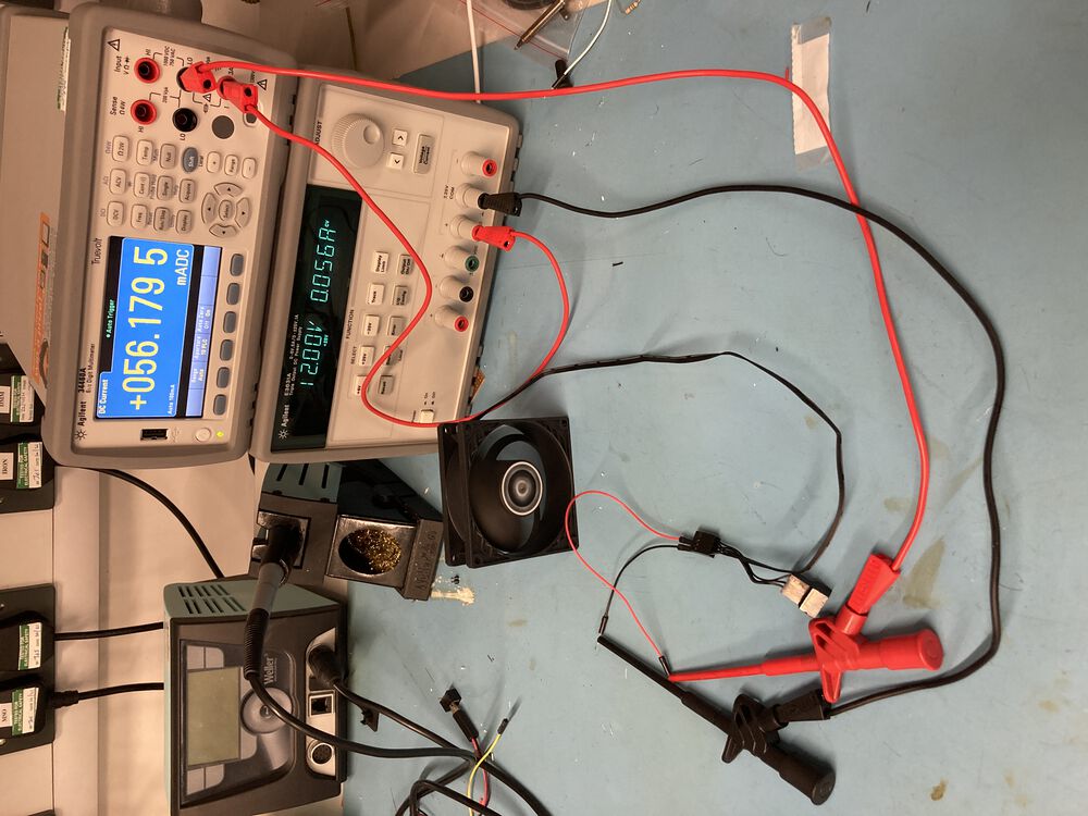
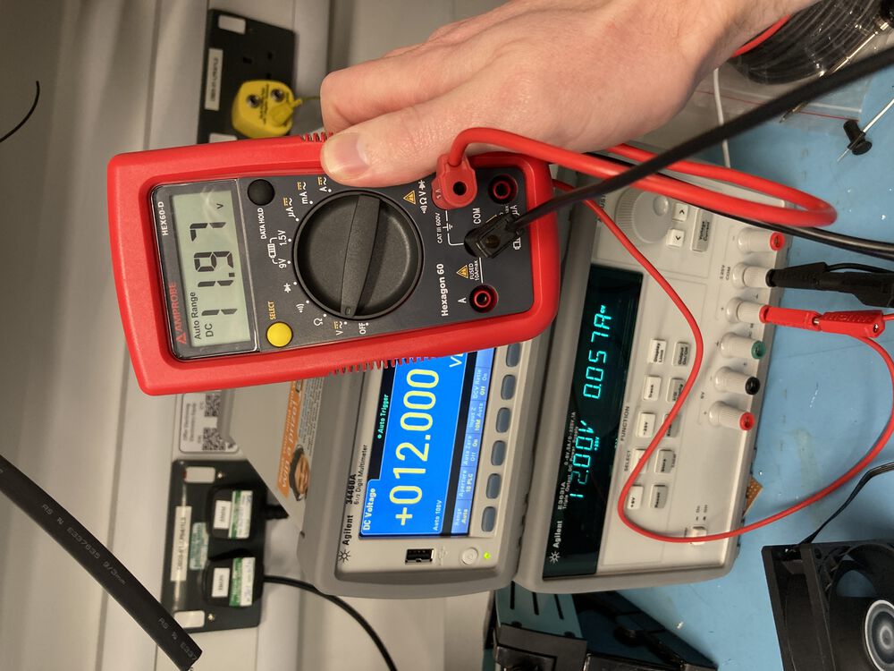
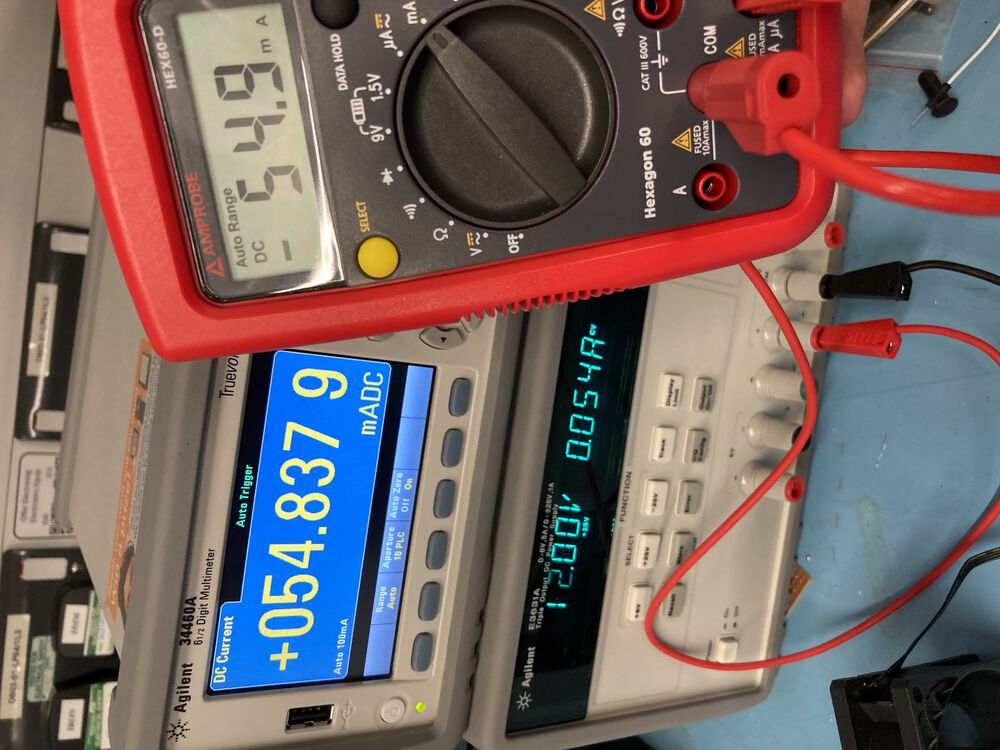
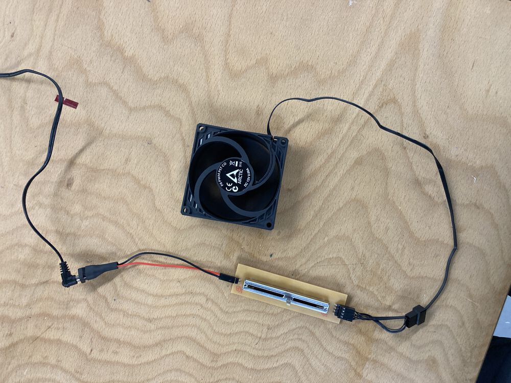
Measured the power consumption of the fan I’ll be using in my project. Compared the bench-top instruments with an affordable option.
Results: 56mA at 12V. P = IV, 0.056A x 12V = 0.67W
See the group page for more.
Note on the design
We are using an ATTINY412 to control the fan. You would not be able to drive a motor directly from one of the 412 pins. But that’s OK. A PWM fan such as we are using takes it’s power from a 12V supply, there is a separate signal at logic levels to control it.
Notes on CAD
Use KiCAD to do schematic capture and PCB layout.
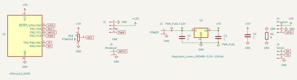
Needed to come back to the schematic and add a 0ohm link to tie together the ground pour.
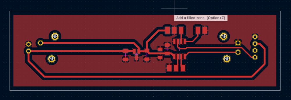
Two sides
First time that I’ve put parts on both sides of the PCB. It’s simply a case of selecting the footprint you want to move to the back and hitting ‘F’ for flip. This will reverse the footprint in view and associate it with B_Cu if it was on F_Cu to start with.
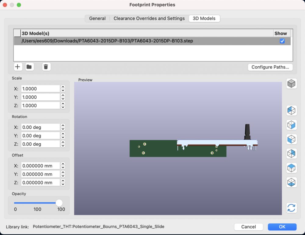
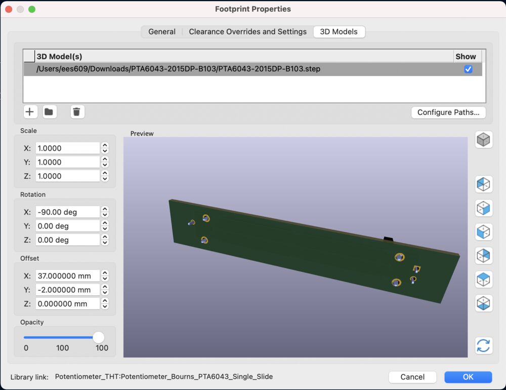
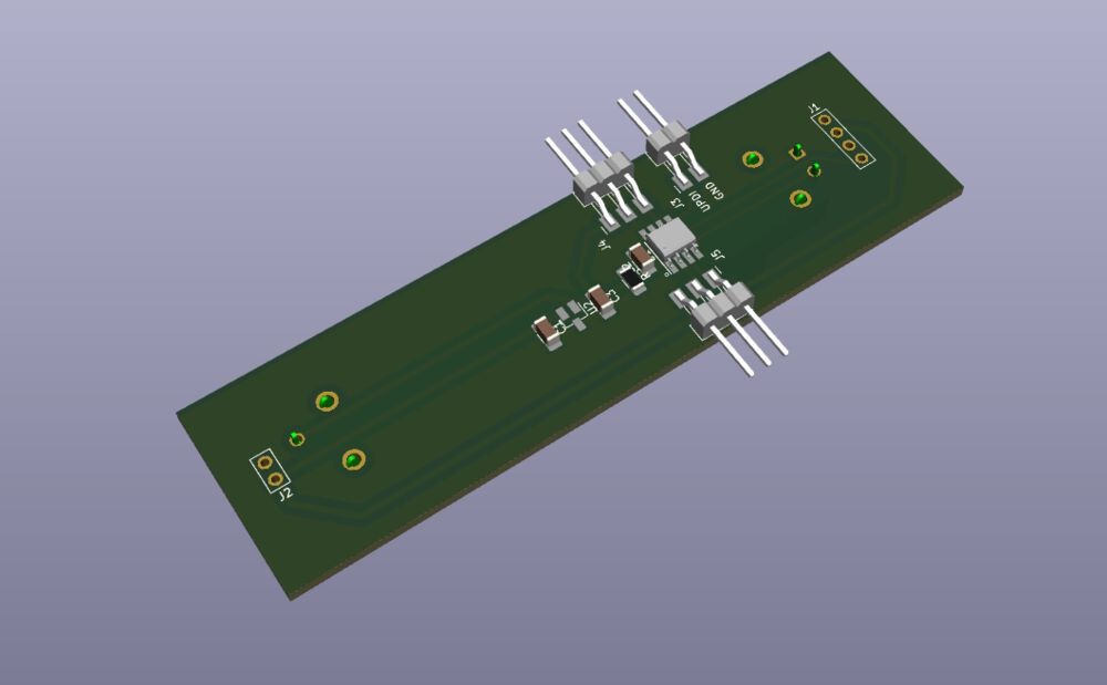
And now in 3D…
The slide potentiomenter data was downloaded from SnapEDA. Schematic and footprints were found just fine, but I needed to fix the path to the 3D model. Double click on the footprint in the PCB view Bring up the ‘Footprint Properties’ dialog. The 3D model needed it’s orientation adjusting before it was ready for the 3D view.
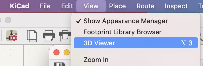
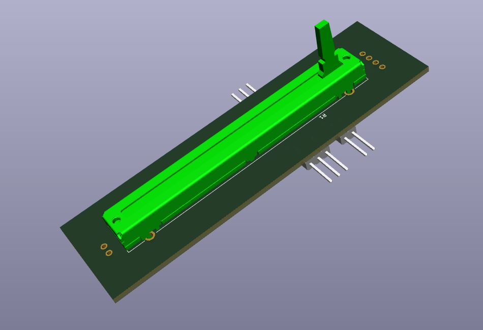
As an extra tool for validating design, the 3D view is excellent. It comes into it’s own when used in conjunction with a 3D modelling tool when designing enclosures for your board.
Notes on CAM
svg files, tweaked in Inkscape and post process in mods.
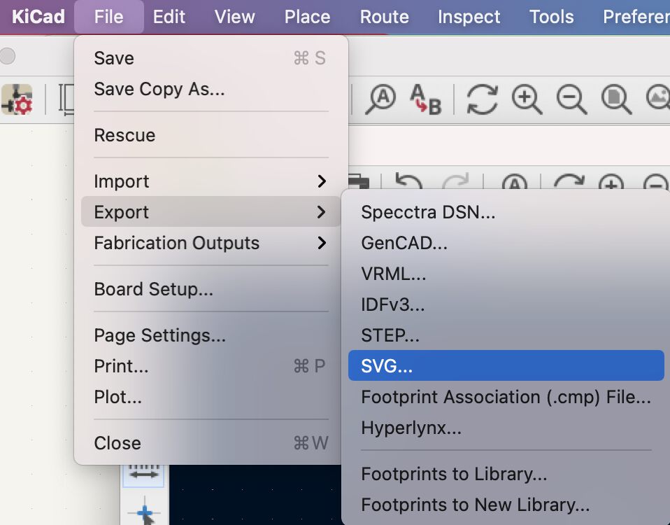
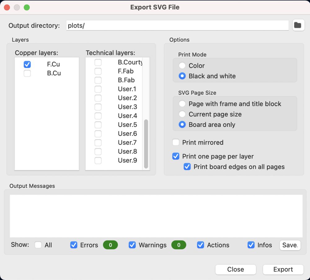
Export
Rather than use the raw plots option I use the Export as SVG, solely for the ‘Board area only’ radio button.
I used Inkscape to make a few tweaks. I have some though hole parts on the board. In the svg images I took the white centres from the drilled pads and copied in place across to the outline file.


Modsproject was able to post process the drill holes with a 0.8mm tool.
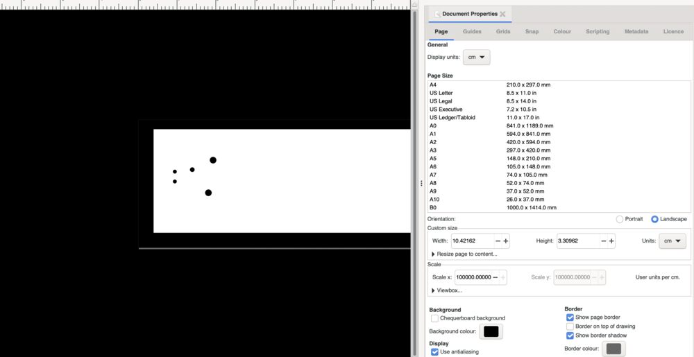
Double outlines
I had an issue with a double outline being produced by modsproject. I had filled out the image with a filled box at the back of the image to remove the transparency. Turned out it was better to get Inkscape to set the ‘Document Properties’ background to black
Manufacture
For explanations of the Manufacturing process used see Electronics Production
Milled fine on the SRM-20
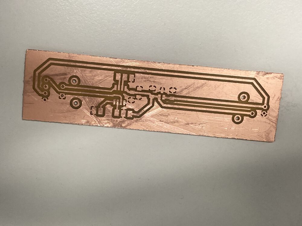
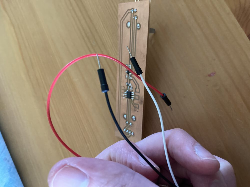
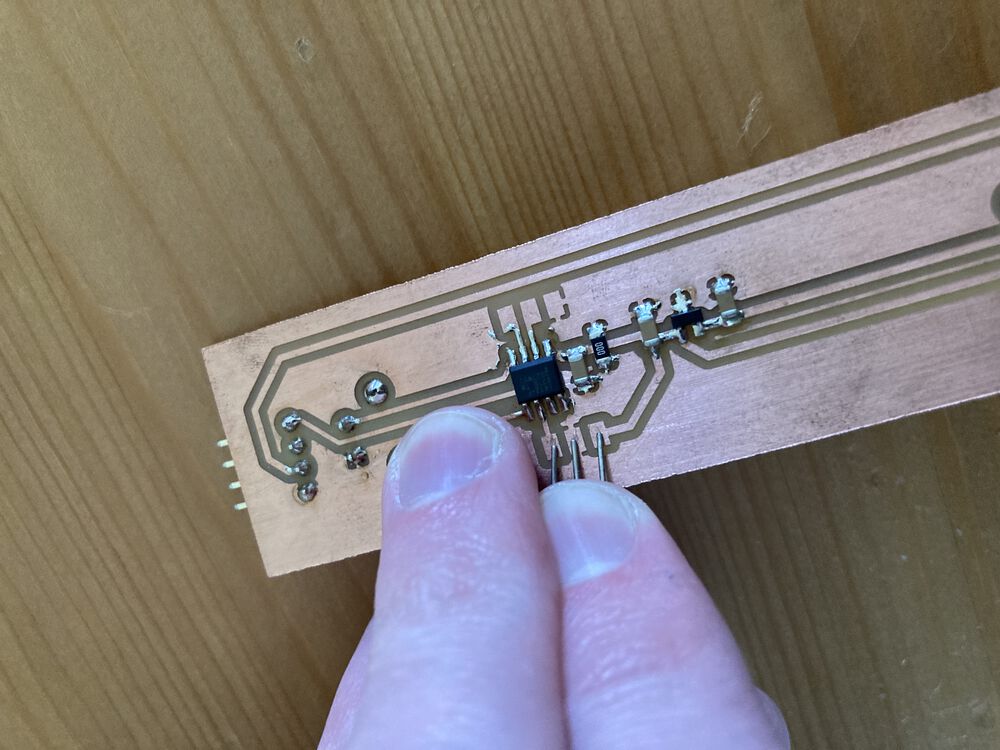
Was pleased the the parts all fit, and not a terrible job of soldering. Making sure that the board is Scotch bright clean makes a big difference to solder flow.
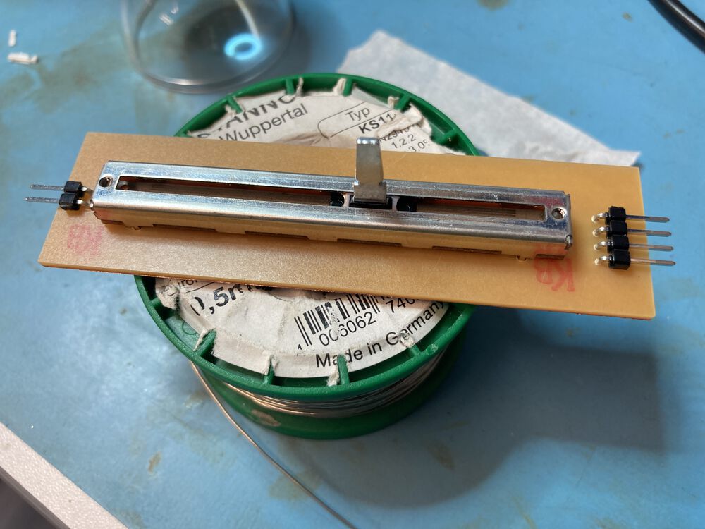
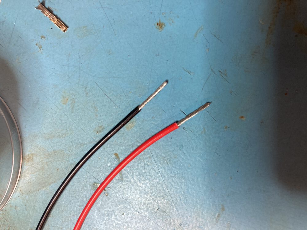
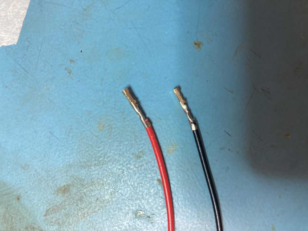
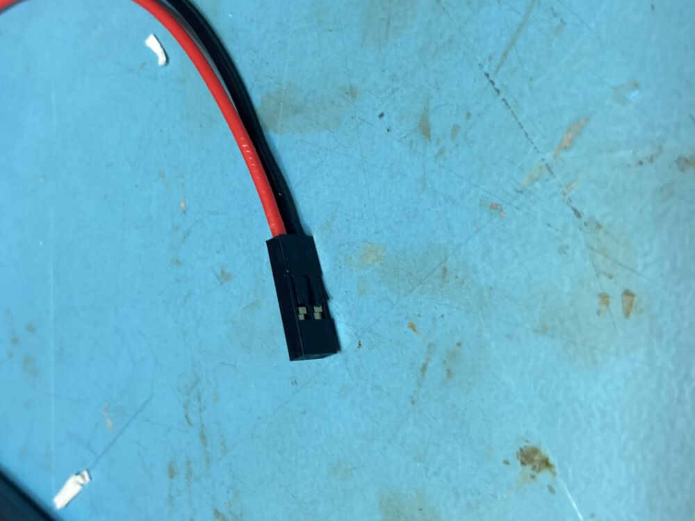
Decided to make up a small cable to tie the board to a wall wart for the supply. Wire was almost too big for the crimps and shells on hand.
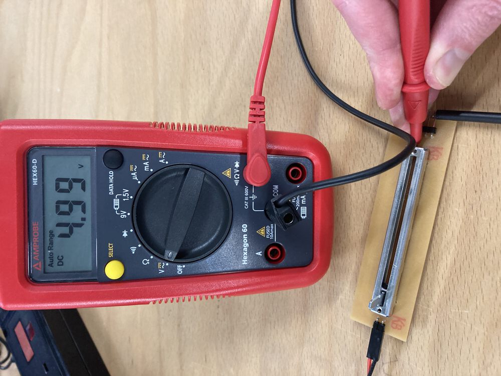
Bring up
Power supply output 5V as expected from a 12V supply. Fan starts to turn even without a PWM signal present.
Programming
To program the board I decided to go simple and use Arduino, making use of the excellent megaTinyCore
Form our schematic we have our output on pin PA3 and the input on PA1. Referring to the pin-map:
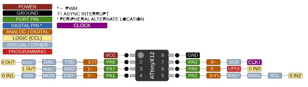
we can use Arduino numbering:
- PA3 <-> pin 4
- PA1 <-> pin 2
A very simple program reads the voltage presented by the sliding potentiometer, converts the 10bit number to an 8bit number suitable for output, where the built in analogWrite uses PWM hardware to emulate a DAC. Not a problem for us as we make use of the PWM output directly to control the fan.
void setup() {
  pinMode(4, OUTPUT);
  pinMode(2, INPUT);
}

void loop() {
  int val = analogRead(2);
  val = map(val, 0, 1023, 0, 255);
  analogWrite(4, val);
  delay(100);
}
Making use of the Arduino numbering can be an issue as different cores can use completely different pin mapping. We can start to rely less on the built in functions of Arduino and re-write the code in a more ‘native C’ as follows:
void setup() {
  PORTA_DIR |= (1 << PIN_PA3);
}

void loop() {
  analogWrite(PIN_PA3, analogRead(PIN_PA1) >> 2);
  delay(100);
}
Both work equally well. We’ll replace more of the code as we learn more native C.
We don’t need no connector…
For flashing the firmware I simply pressed the supply and UPDI connectors to the pads. I’ll be adding some pogo pins to my next parts order. The main problem with the fingers option was maintaining a correct spacing.
Hero shot
It works as expected (excuse the rattling in the background) In the video here you can see the sophisticated fan flow indicator responding to the different amount of air being pushed at different set positions og the slide potentiometer:
Measuring the finished device
Once the board was constructed I characterised it.
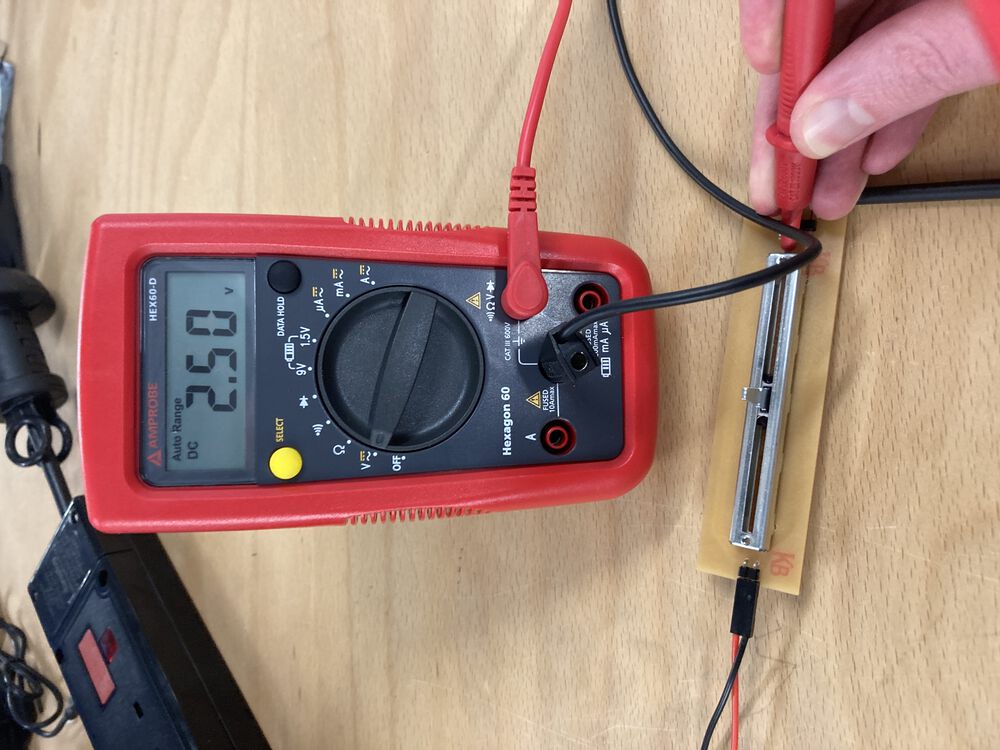
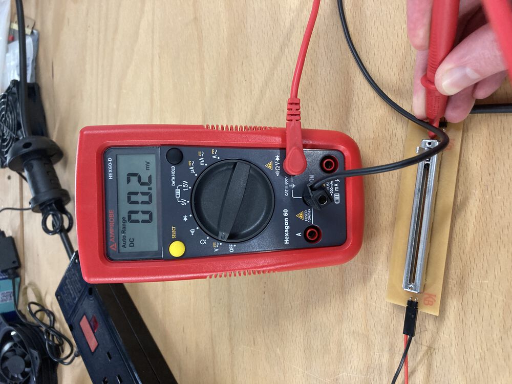
We have come simple measurements from the wiper of the potentiometer at different positions:
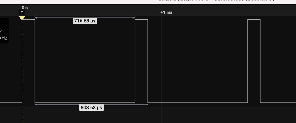
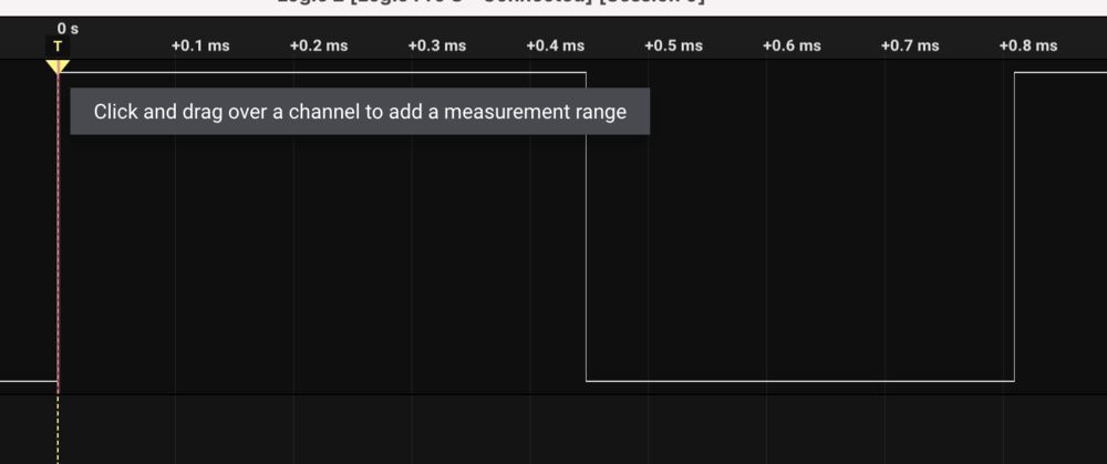
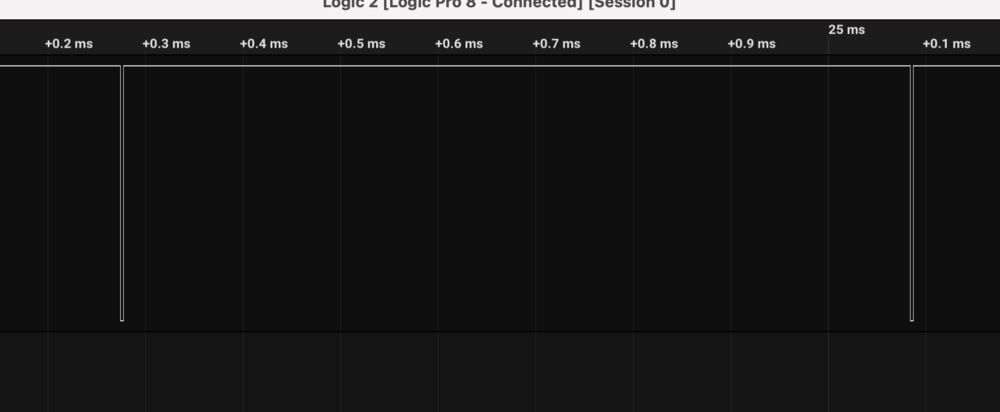
And a logic analyser output of the resulting PWM signal: