3. Computer Aided Design
This week: - Modelled experimental objects/part of a possible project in 2D and 3D software - Shown how you did it with words/images/screenshots - Included your original design files
Files
Shelf - growing_rack_shelf.FCStd Leg - growing_rack_leg.FCStd Assembly - growing_rack_assembly.FCStd
portable format:
Shelf - growing_rack_shelf.stl Leg - growing_rack_leg.stl Assembly - growing_rack_assembly.stl
3D Design in FreeCAD
For Computer Aided Design I decided to model the Quarter Metre Farm rack, as a basis for future additions and developments. Before I get to that I followed a first tutorial to start getting familiar with the fundamentals.
Choosing FreeCAD because I would like to make sure we have a fully open workflow available for our milling processes. Although still allowing non commercial use, the recent changes to Fusion 360 licensing has made some in the maker community wary of adopting the tool, with many switching to FreeCAD.
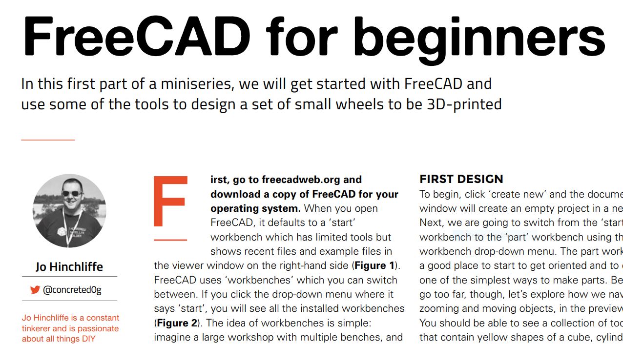
Following a Simple Tutorial
A friend writes for HackSpace magazine where he’s been contributing a FreeCAD tutorial staring in issue 37.
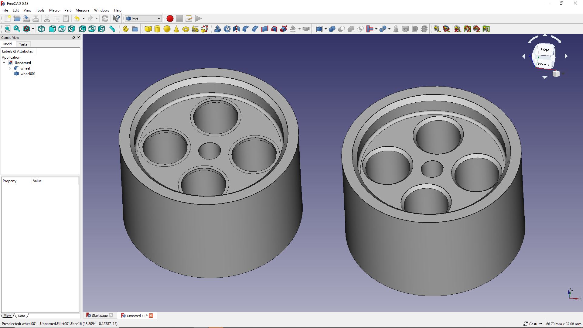
Started with creating a wheel from Boolean operations on primitives
Application of the basics to a foundational model
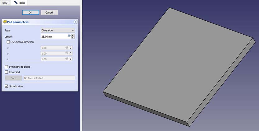
Starting a new file the first thing we do is create a Body.
This appears in our model tree, acting as the root node for a 3D object. Adding a Sketch to the Body and we begin to describe the form of the 3D object. A sketch can be thought of as a 2D projection of a 3D object. Creating the sketch uses the drawing tools and the constraints.


A fully constrained sketch, where the shape has been drawn and all dimensions defined, can be closed. Here we’ve dimensioned one side of the square, made an orthogonal side equal and constrained the square equally about the origin.
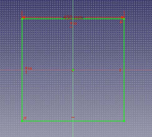
With a sketch in hand you have a few options for next step, initially we’ll ‘Pad’ our square to make up the contained volume of a shelf.
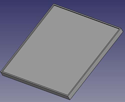
Once we have our outline shape we need to make some alterations. These are based on more sketches, describing additional aspects of our 3D form.
These new sketches can be drawn onto a surface of our initial form, but best practice suggests that we create a coincident Datum Plane where we’ll add out next sketch.

Datum Plane third tool from the left. When we have our next simple sketch, created in much the same way as our last square, instead of Pad, this time we will create a Pocket. A second deeper pocket is taken out of the reverse.
(The next action on the model was to knock some corners off with a fillet, well be describing fillets as a last step, we did the same sort of thing here.)
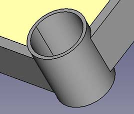
For our description of the basic tools we’ll next work towards adding some corner tubes. Starting by adding a new body to the part we created a cylinder from a sketched circle and a pad. A right click on the new body reveals a Transform option that allows us to move the body around.
![]()
Change the increment and you can place the part where you want it in one jump.
Once we have four cylinders placed on four corners we do our first Boolean operation. Next to some shaping tools we’ll find our double blue circle Boolean tool.

A Fuse will make a single Body from those listed. Leaving one node in our model tree where before there were five.
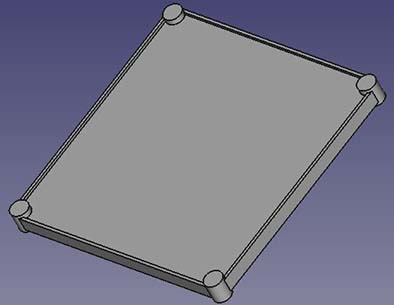
Creating slightly more slender cylinders and locating them again at the corners allows us to demonstrate another Boolean operation, that will allow us to remove material form our form.
As a last touch well Fillet some edges, first of the shaping tools above, a blue cube with rounded red edge. Selecting the tool, a number of edges and a dimension will round off those edges.
A first Assembly
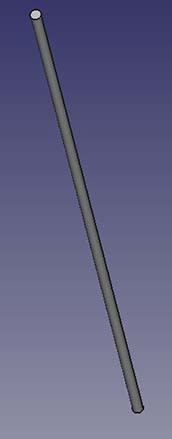
Once we have a ‘shelf’ save the file and begin again. This time a simple cylinder tall and thin acting as a leg for our model.
With some parts in-hand we need to instal a new tool box, the A2Plus workbench. Which will give us our first insight into creating Assemblies. The first tool lets us add files to our assembly, well start with a single shelf and four legs.
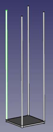
Parts are aligned by selecting features on two, and adding a constraint. We used constraints here to make the legs coaxial with the holes in the shelf corners, and the surface of the bottom of the leg coincident with the lowest face of the shelf. Additional shelves are imported, tied to one of the legs and constrained to be parallel with the first shelf, offset from the bottom to its final height.
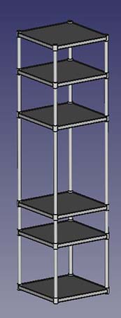
This model will allow us to test the shape and form of any additions we wish to make to the test bed.
2D
Inkscape
For examples of Inkscape being used see Electronics Design
Photoshop
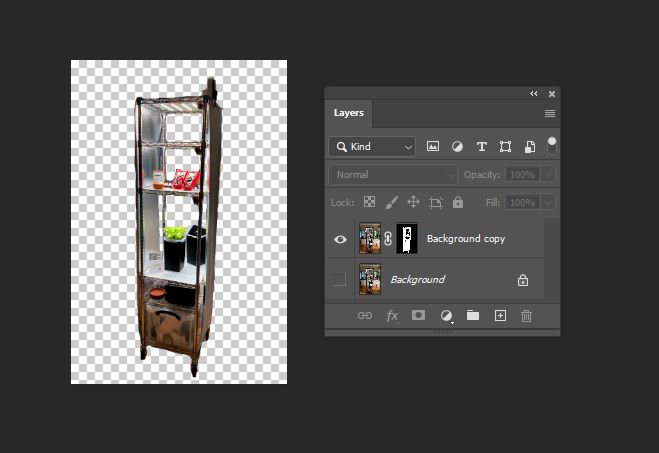
Had a go at creating a layer mask in Photoshop to remove a cluttered background from an image.
To make a mask:
- Select the layer we want to work on
- click tha add layer mask button
- make sure the mask is active, ie has white border in the layers panel
- get a brush and paint into the mask, black to cut away, white to show.
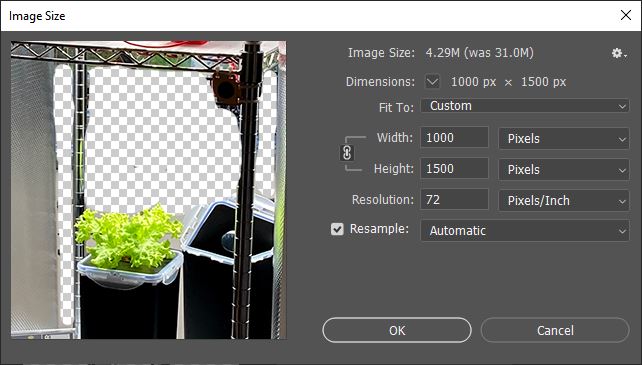
Where we’ve not used the command line, images were scaled in Photoshop
Illustrator
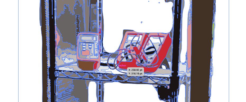
Following that we started to look at vectorising the image with Image Trace in Illustrator. Note to self, remember to select ‘Ignore White’ in the dialog.
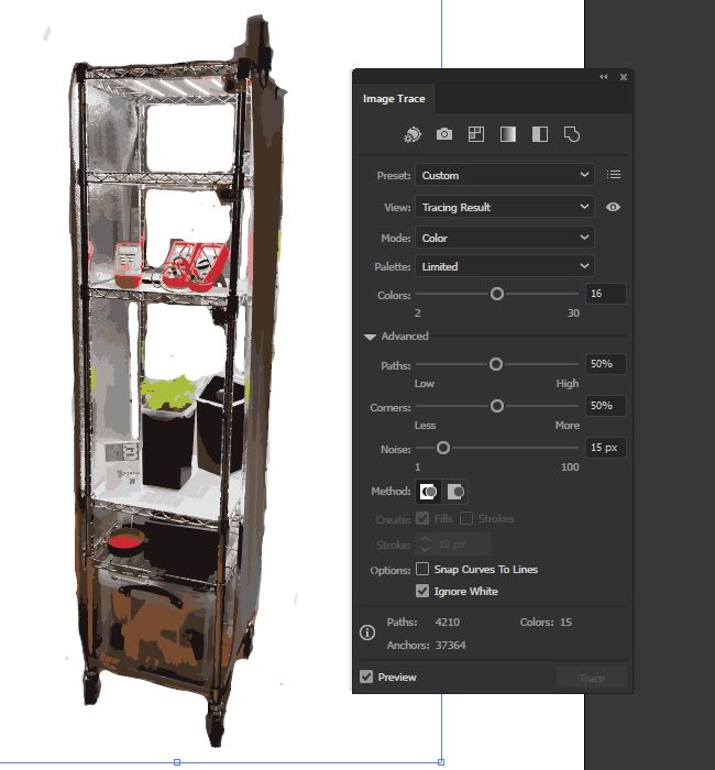
I went for a low colour fidelity
Next lets do some illustration from scratch, adding the canonical example
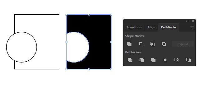
A particular example where we took the gaps out of a frame, rather than building the frame from lines.
![]()
Fill it out with some plants
![]()
More examples
For more examples of output from these tools see Project Diary - Iconography
For an example of vector graphics see the final files ready for vinyl cutting in next weeks assignment:
Tetrahedron eps - half_tetra.eps