Project diary
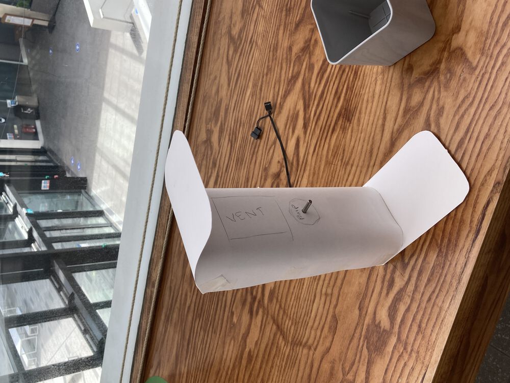
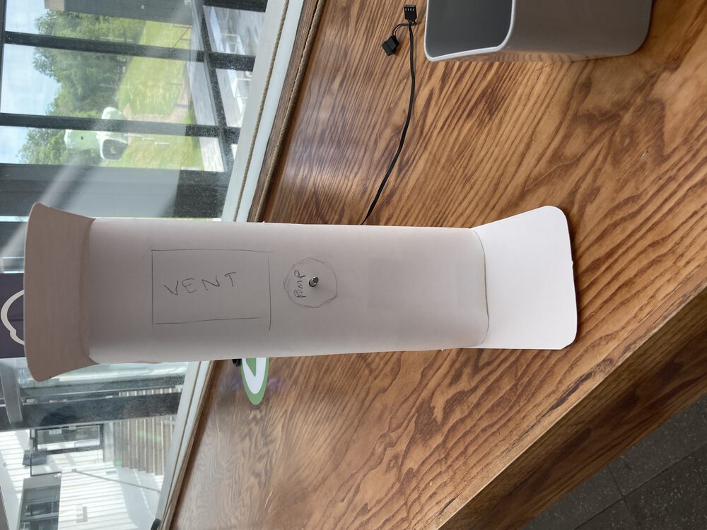
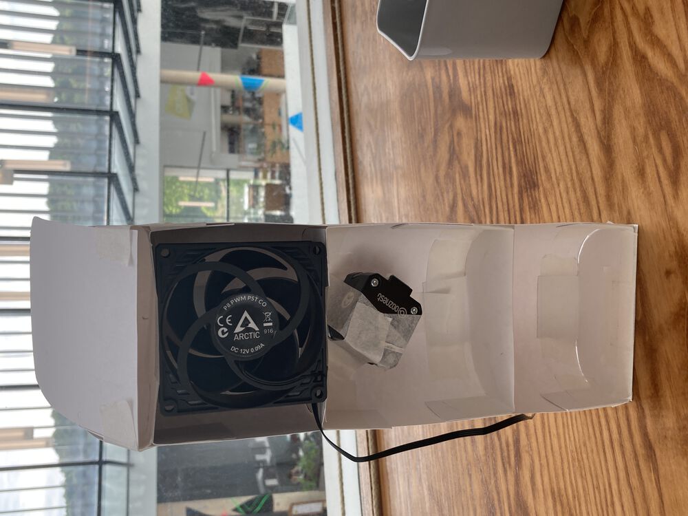
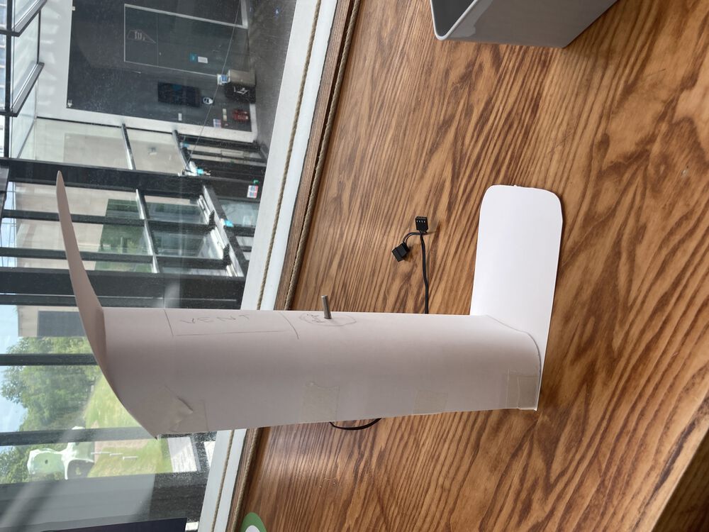
Just about there
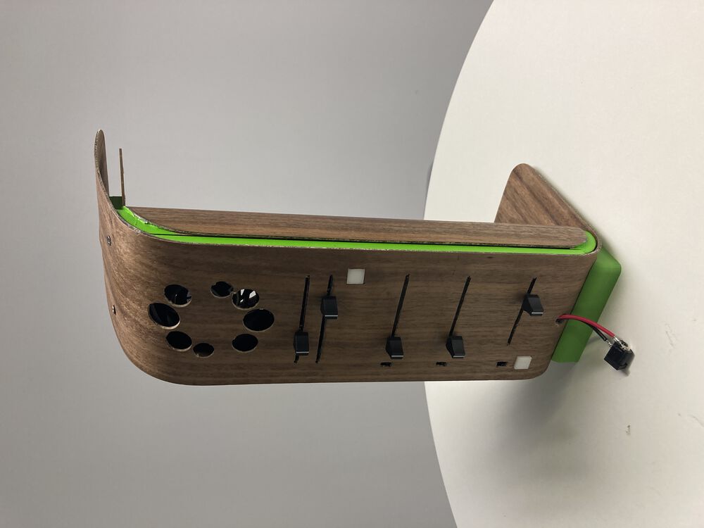
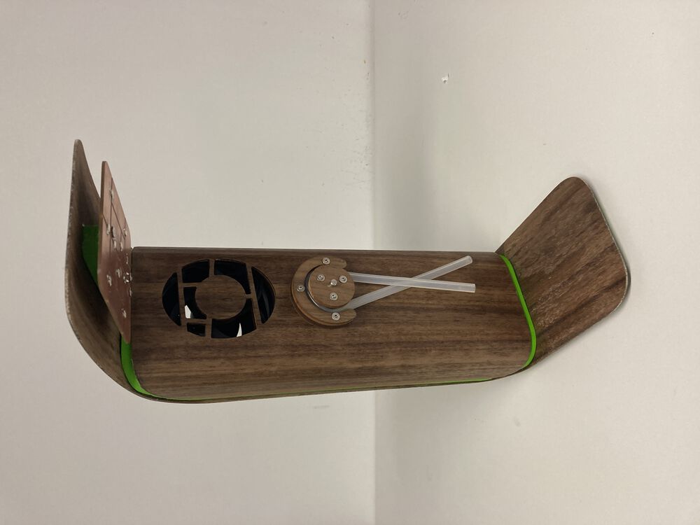
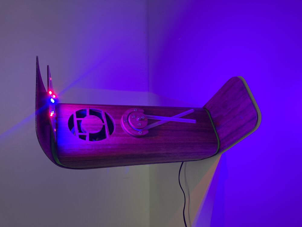
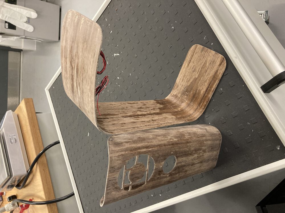
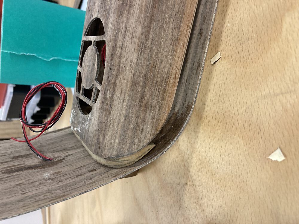
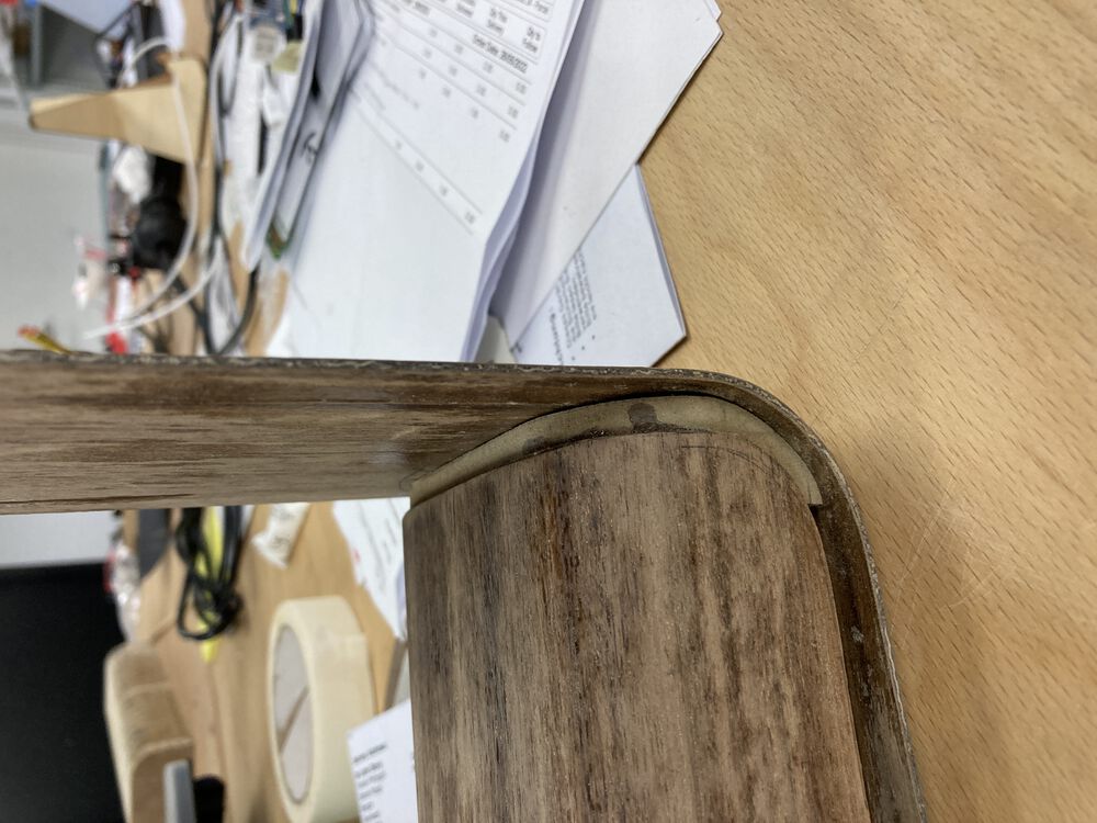
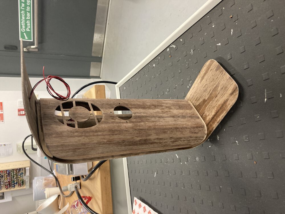
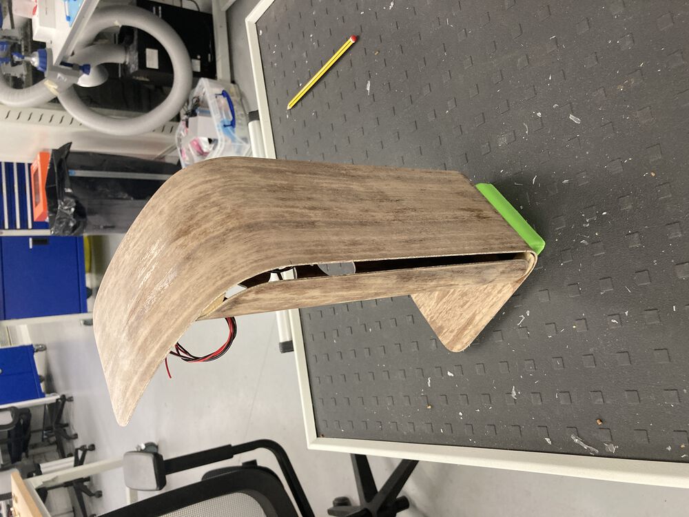
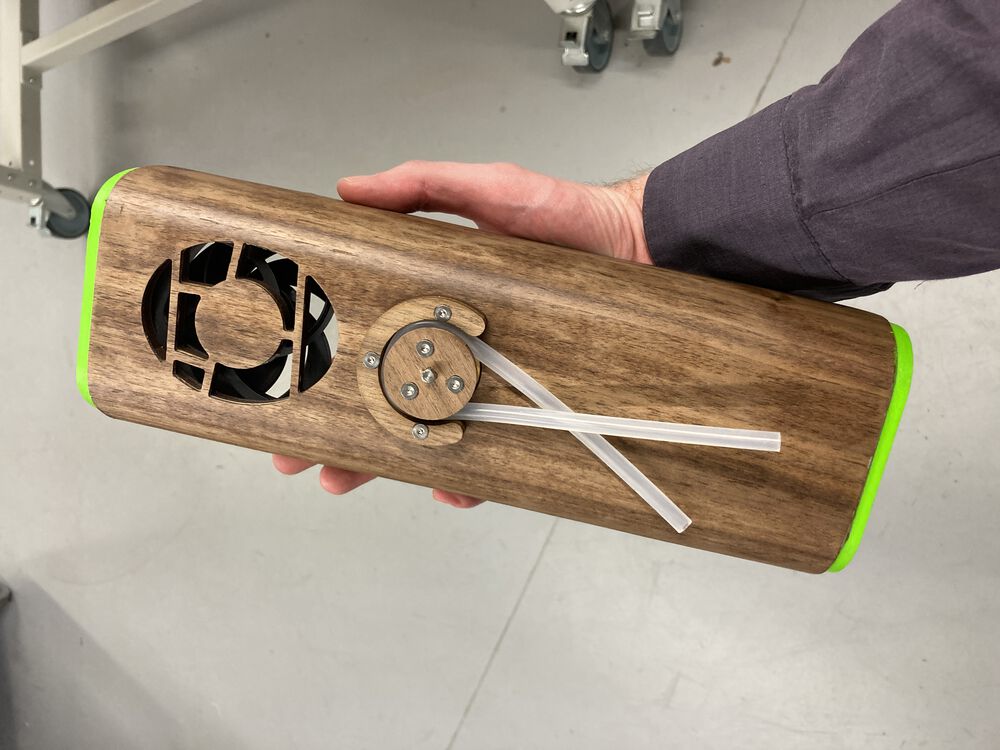
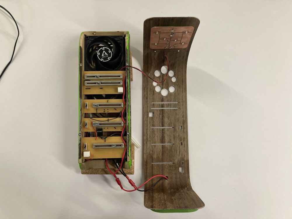
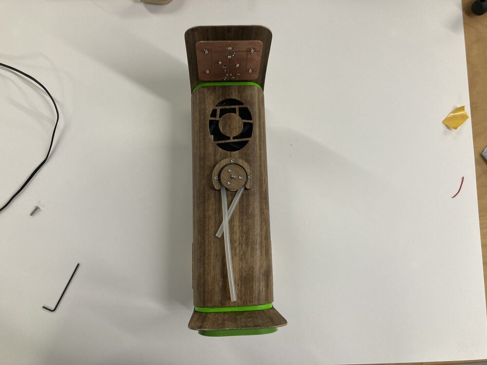
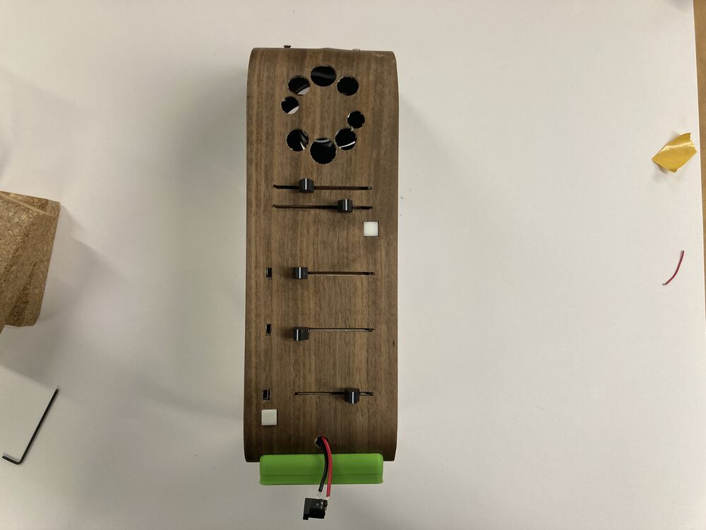
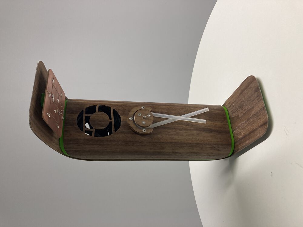
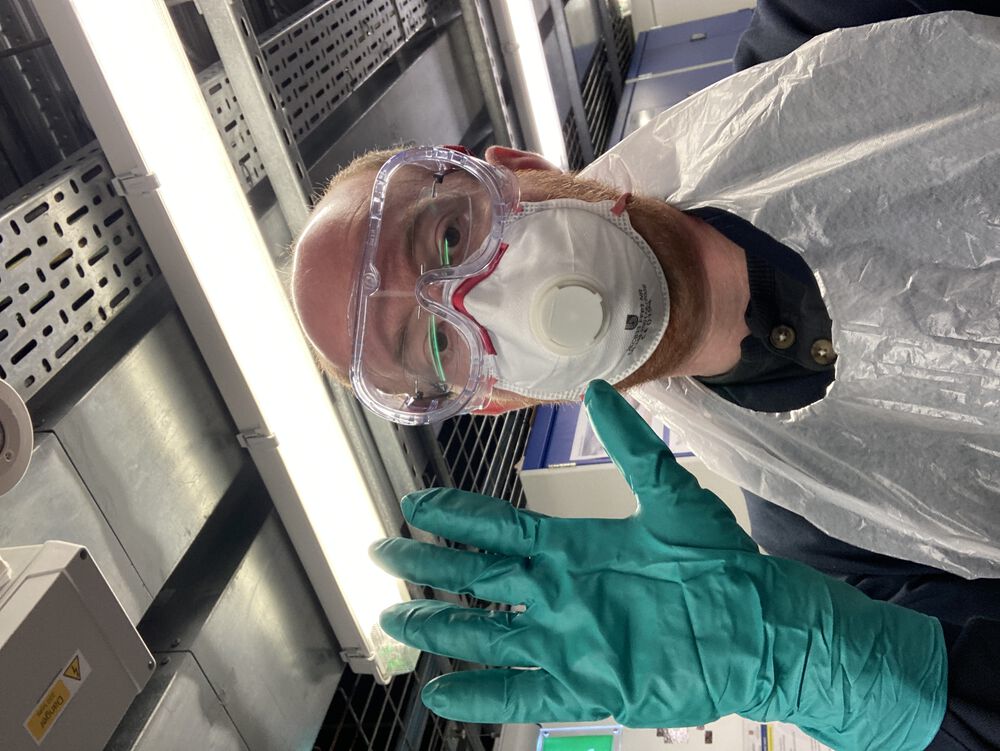
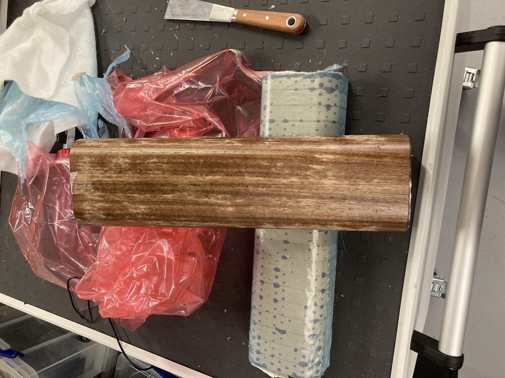
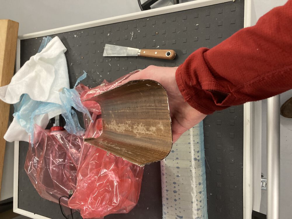
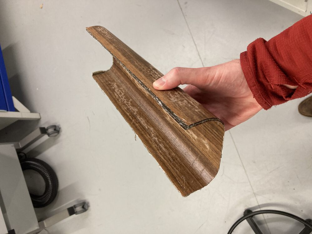
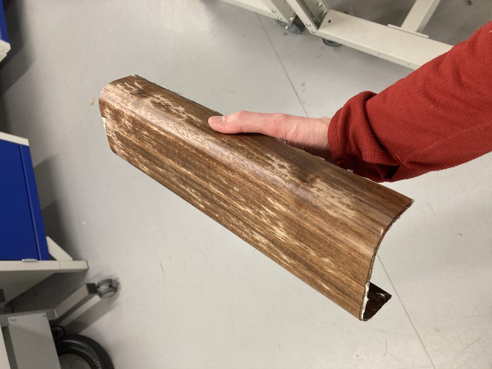
The hero shots, connector for power to be sorted out when supply chain spits one out:
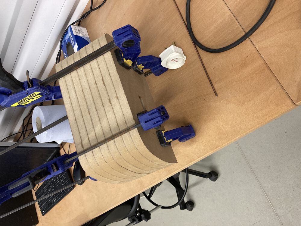
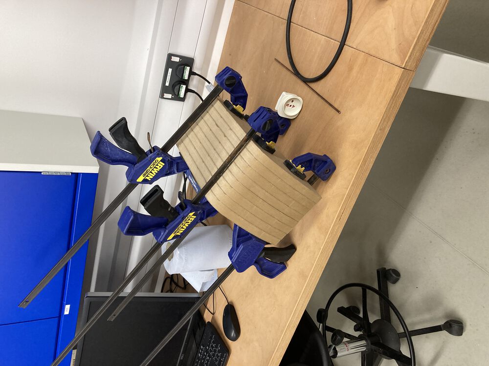
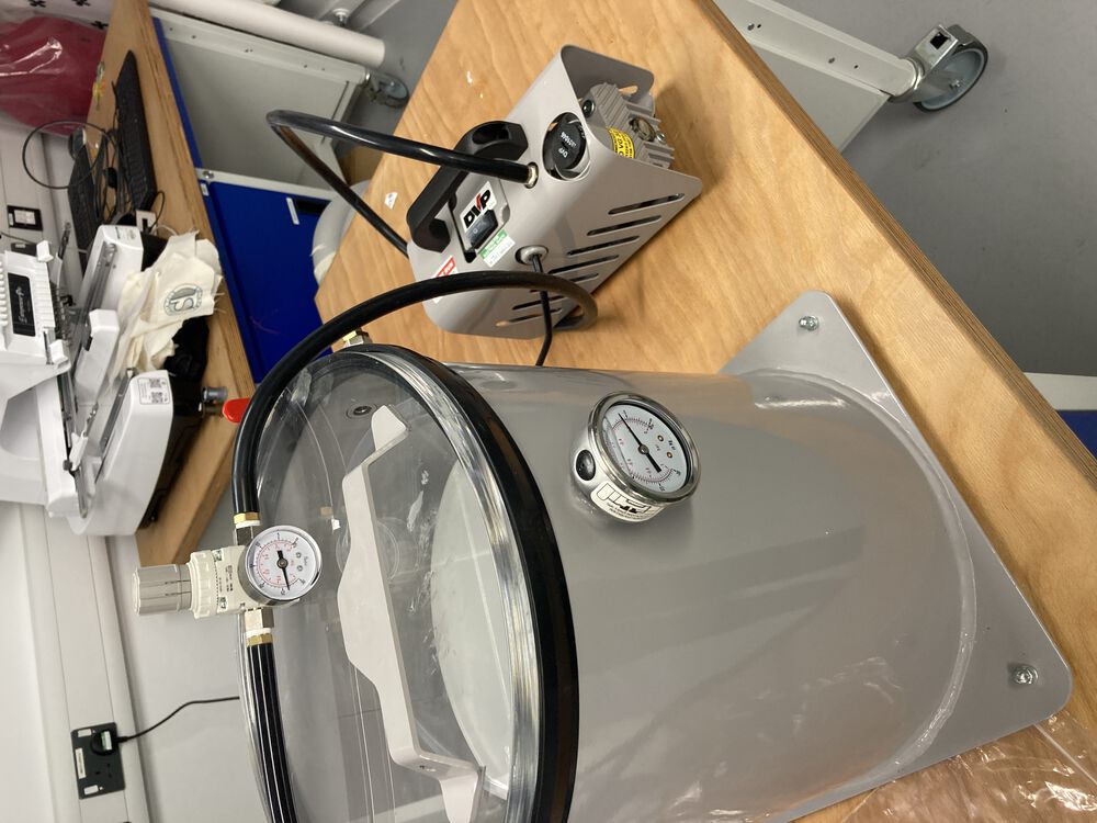
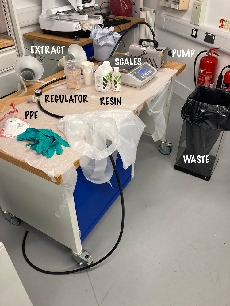
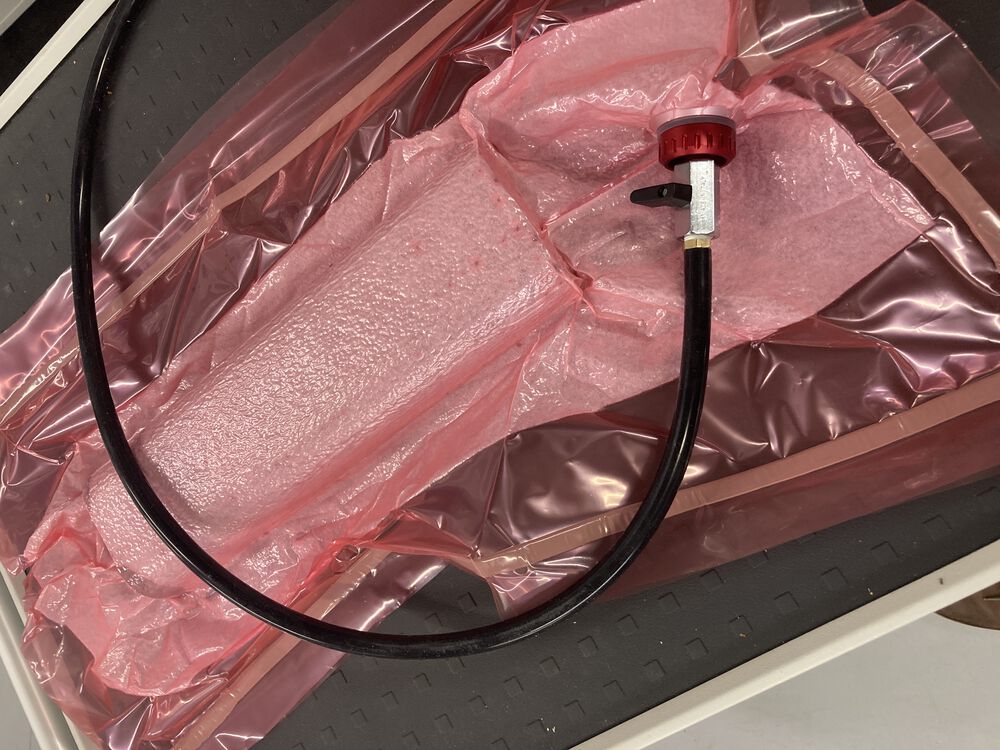
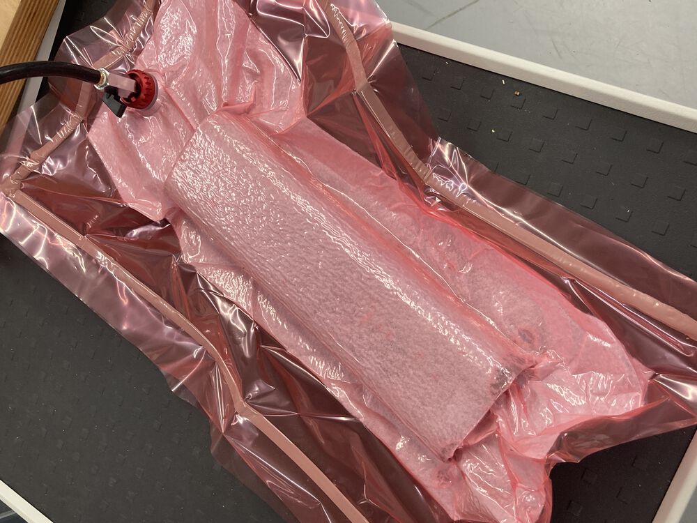
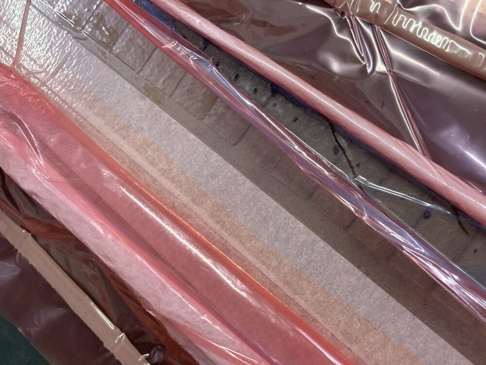
Wild Card - vaccum bagging
For a more in depth look at how the two main forms were made take a look at Wild card week
Build progress III
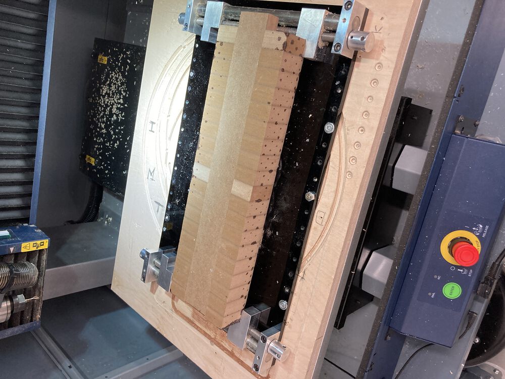
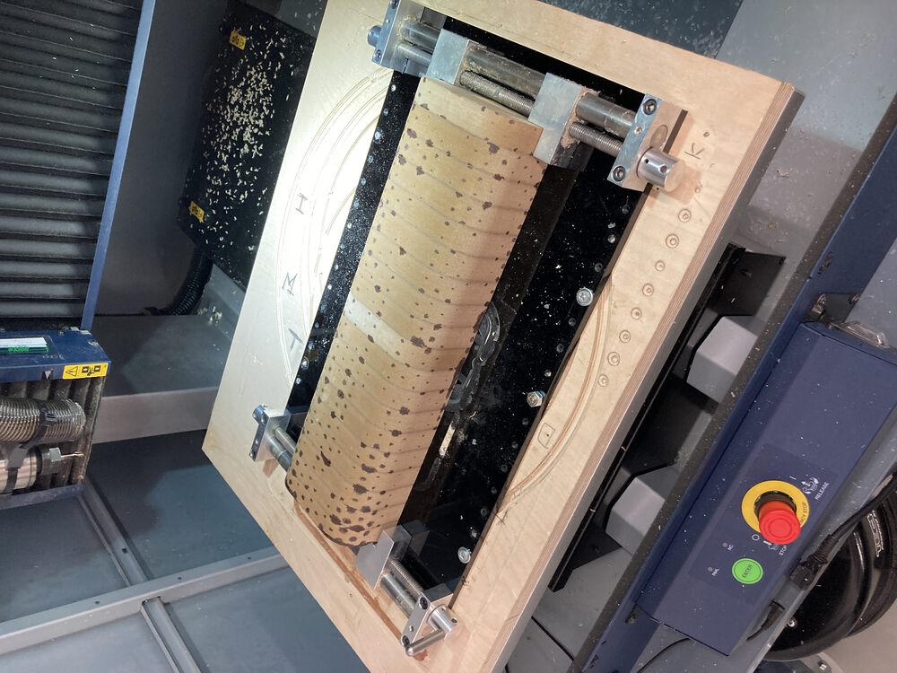
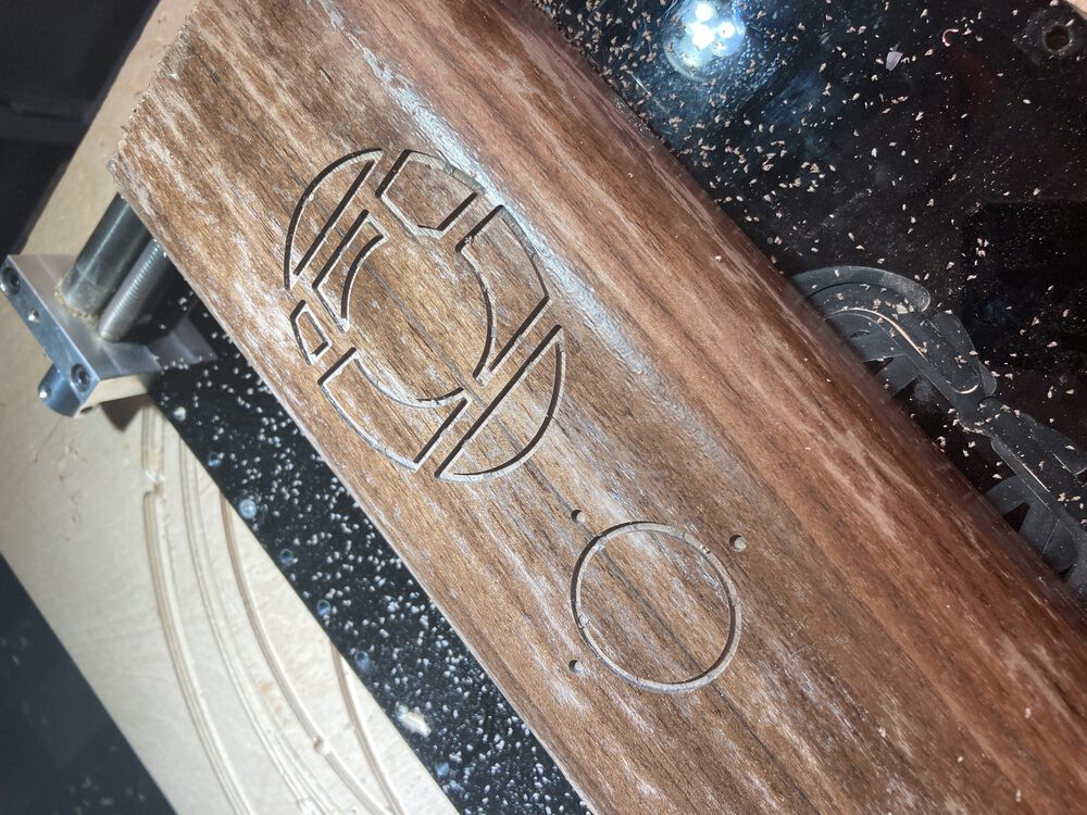
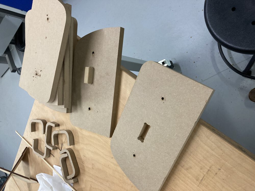
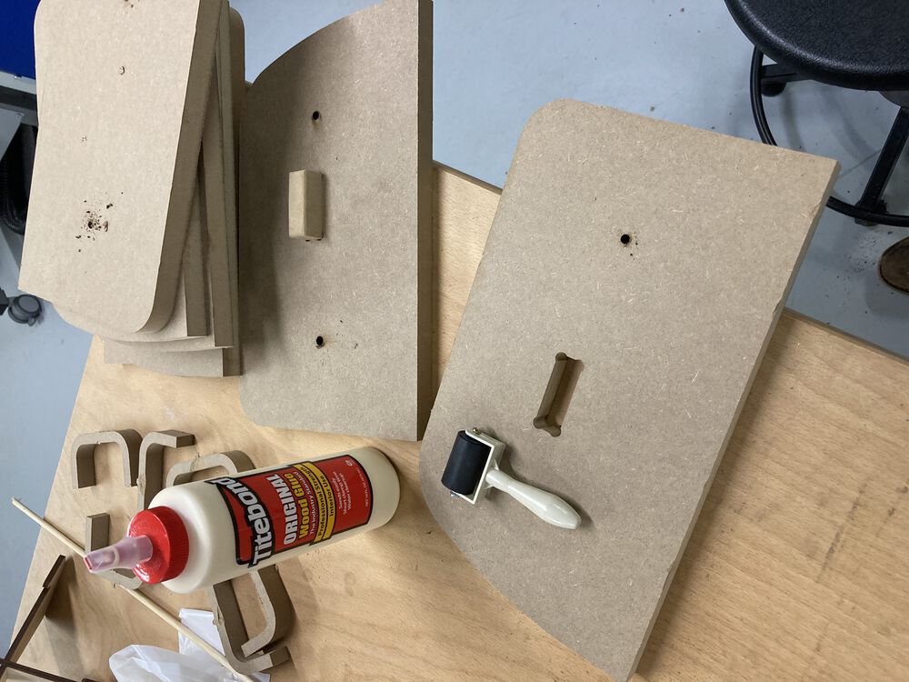
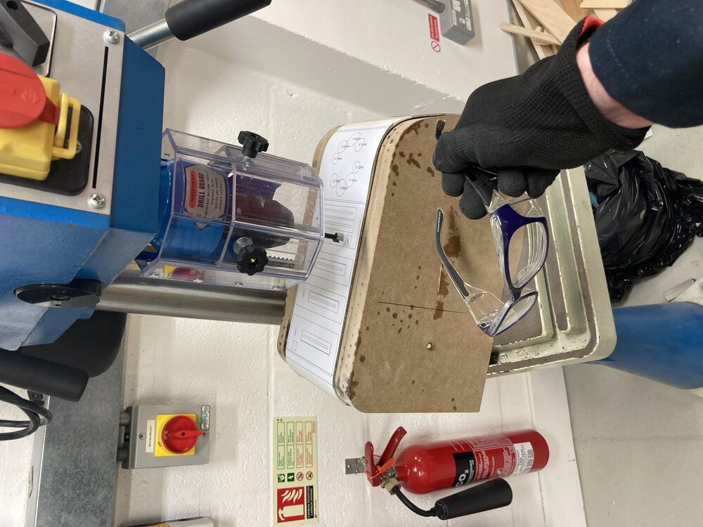
Fixturing the front form for milling out the fan grille and pump apeture:
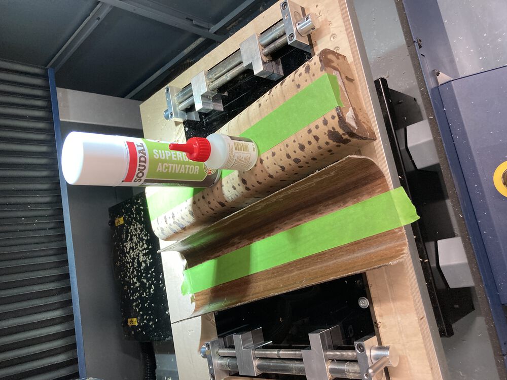
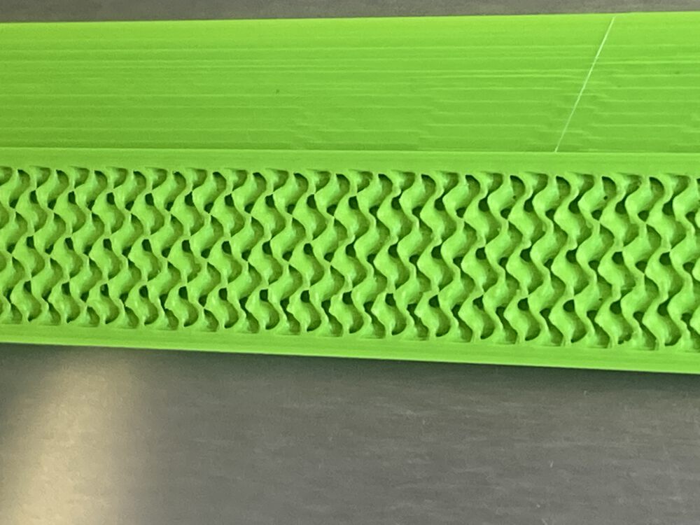
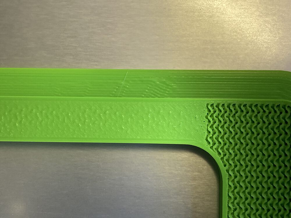
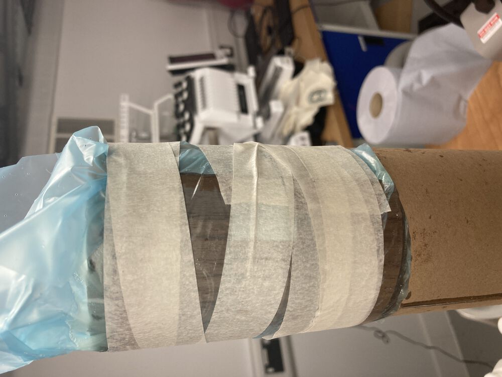
Putting together the second form for vacumm bagging:
Perfect time for an update:

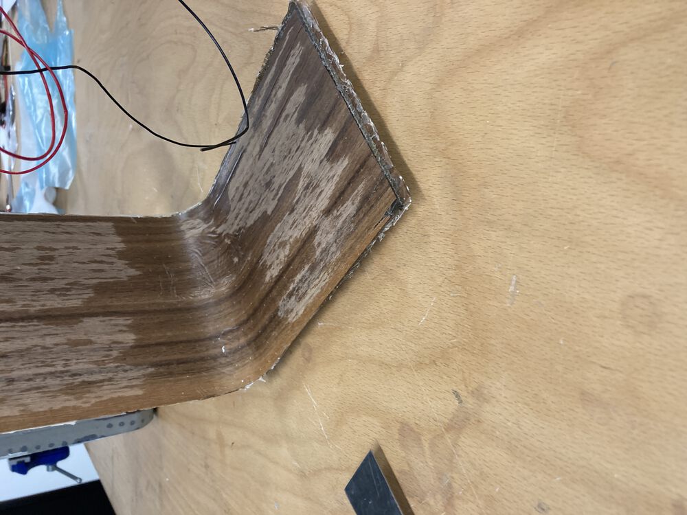
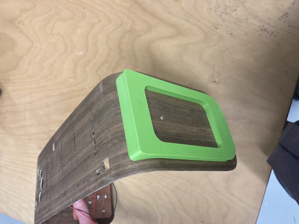
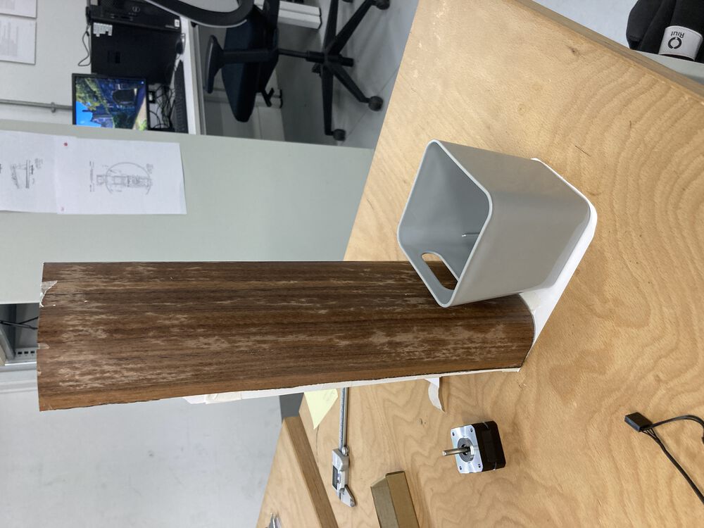
Mid print on the foot and the finished result:
Second form sits o the foot perfectly:
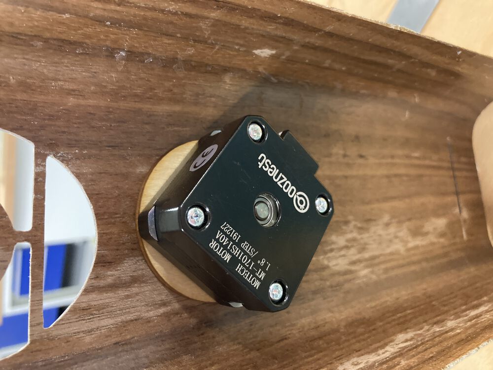
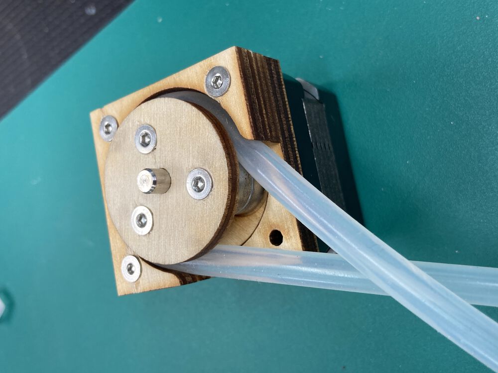
Fitting the pump:
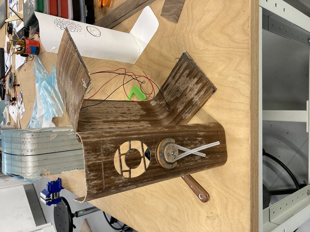
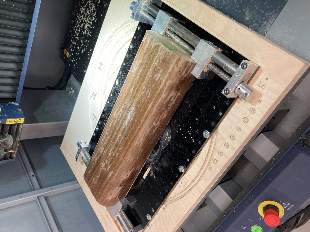
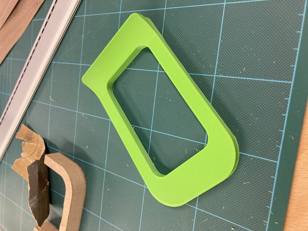
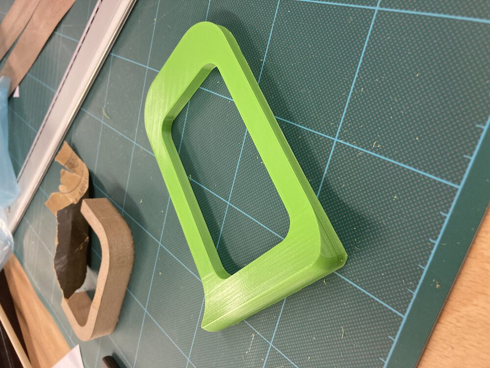
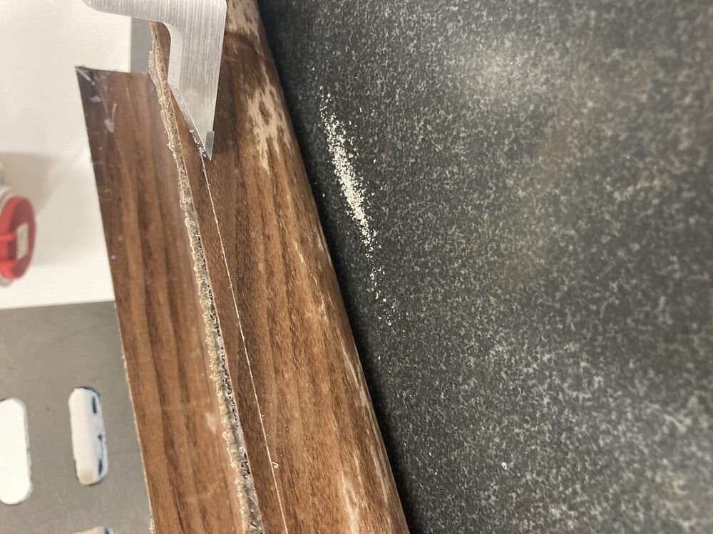
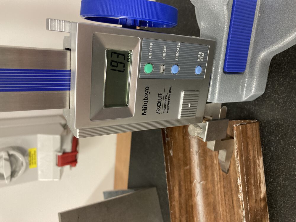
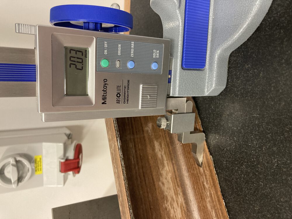
Cutting down the second form:
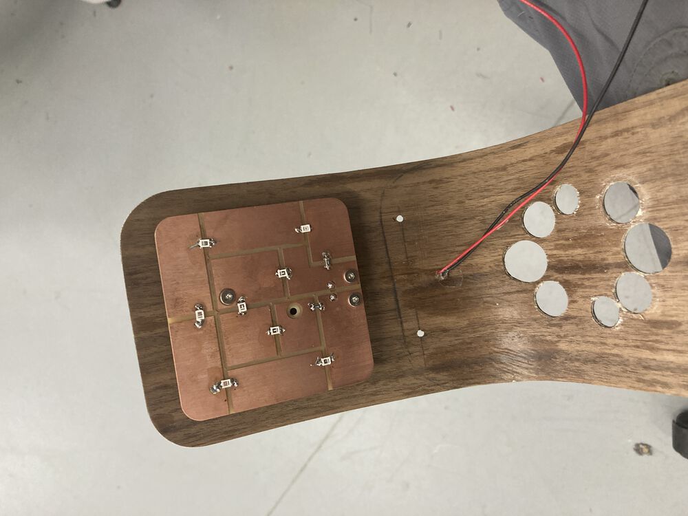
Make spacer for LED panel:
Mating parts manual fit up:
Cutting rear fan grill with Forstner bits:
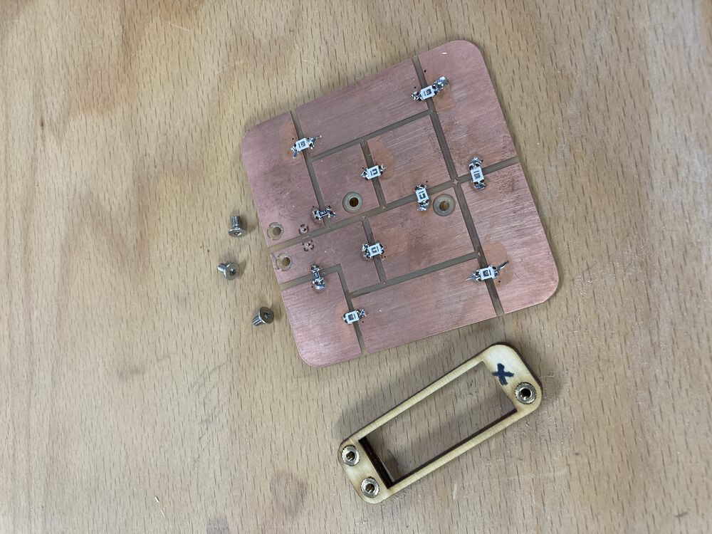
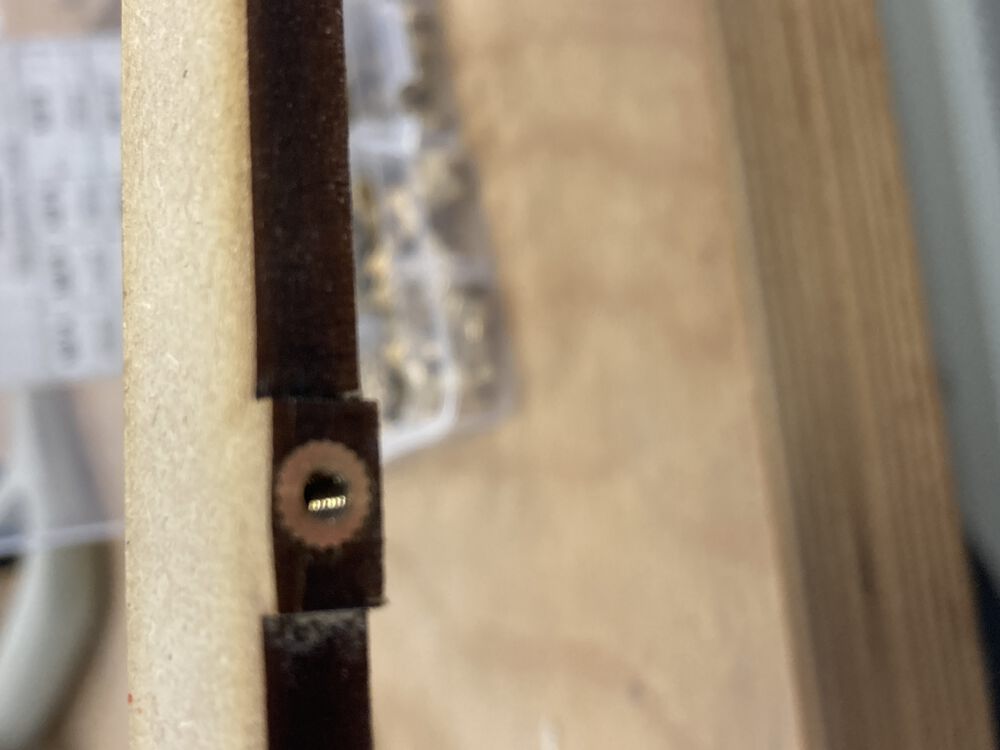
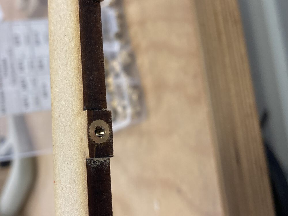
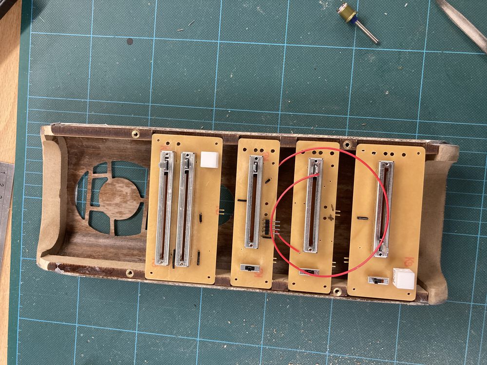
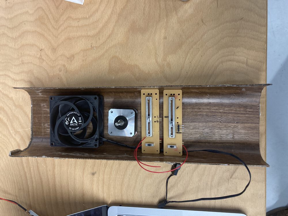
PCB retainers:
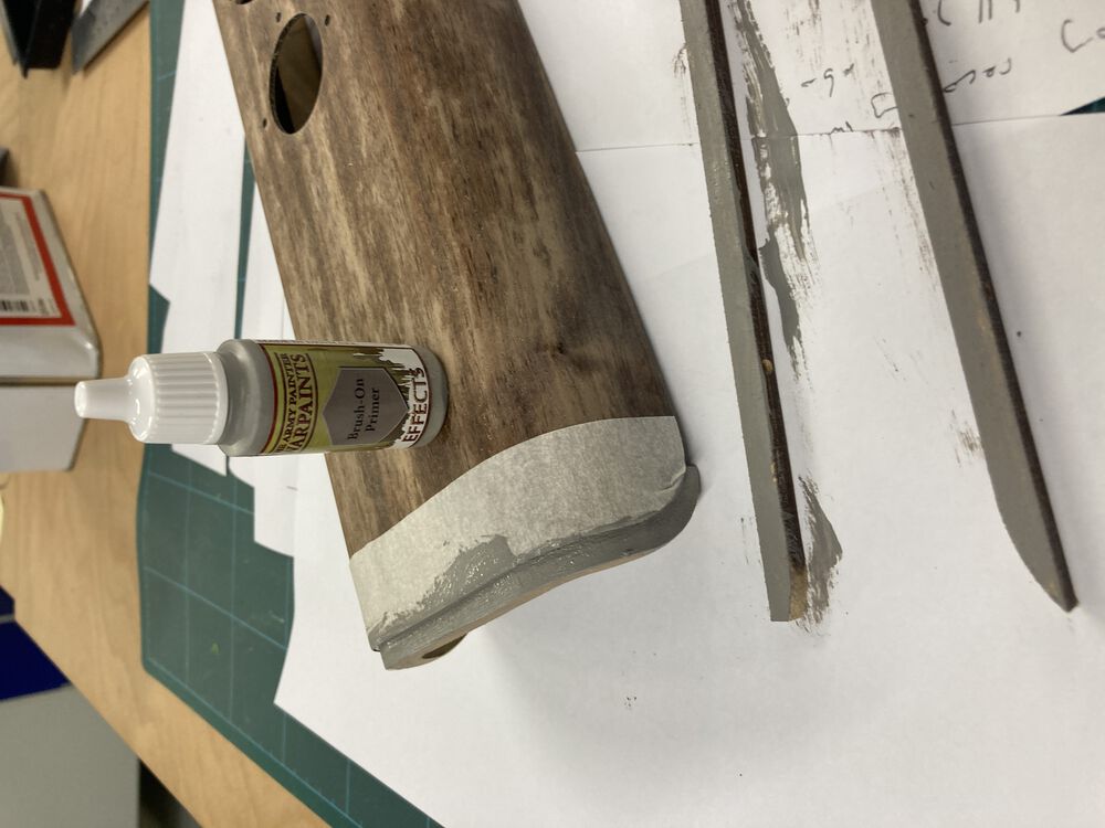
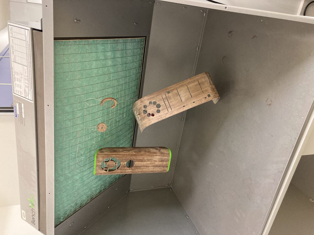
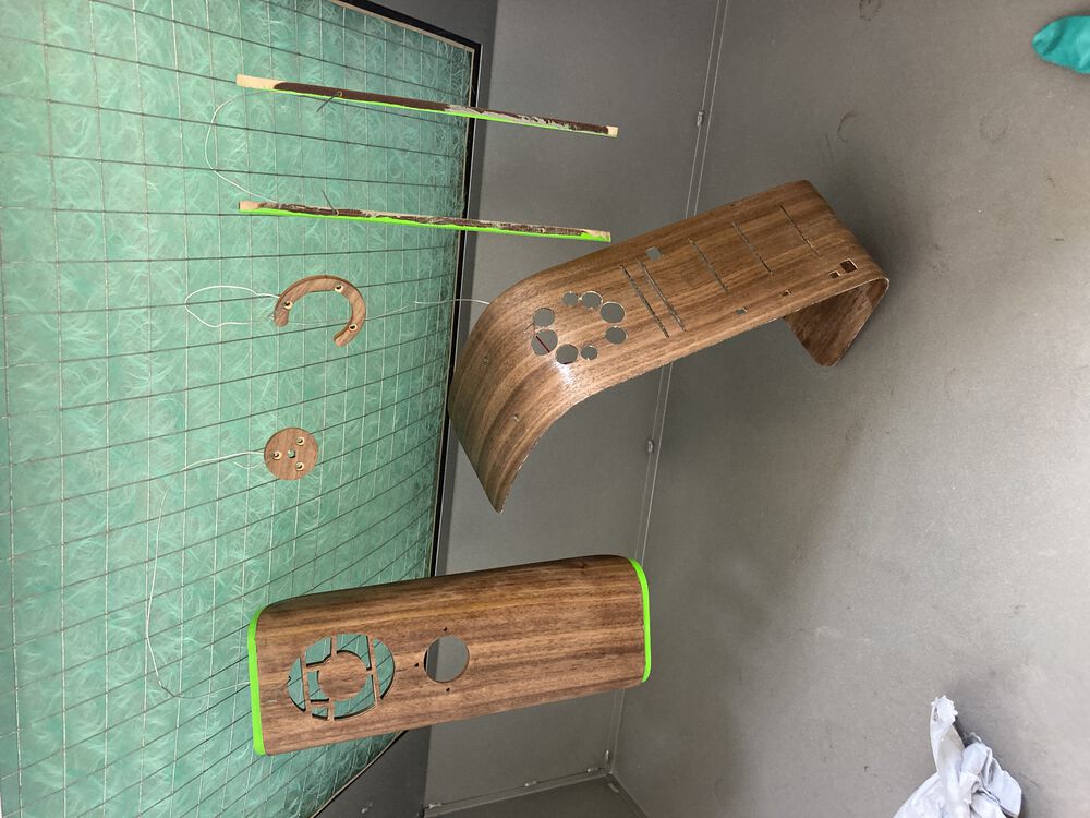
Priming the MDF:
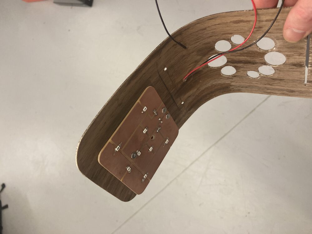
Board retainers fit into first form:
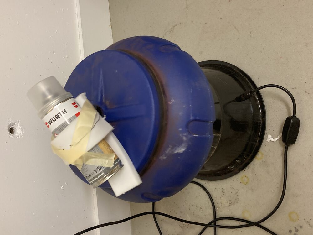
Improvised spray can rattler, couple of layers of laquer finish:
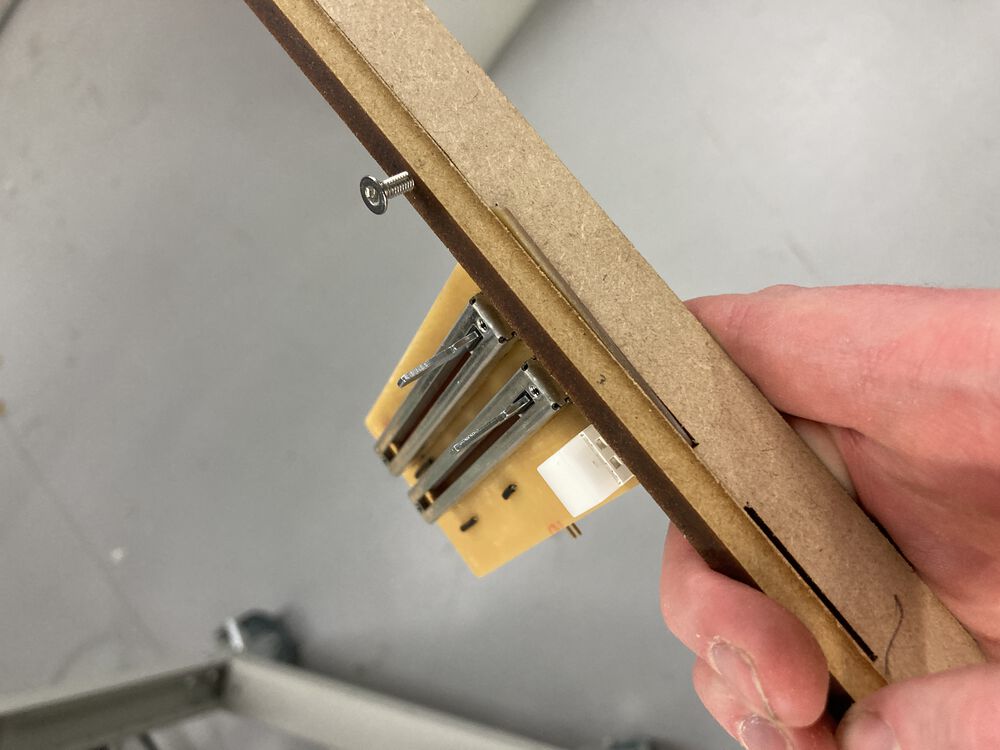
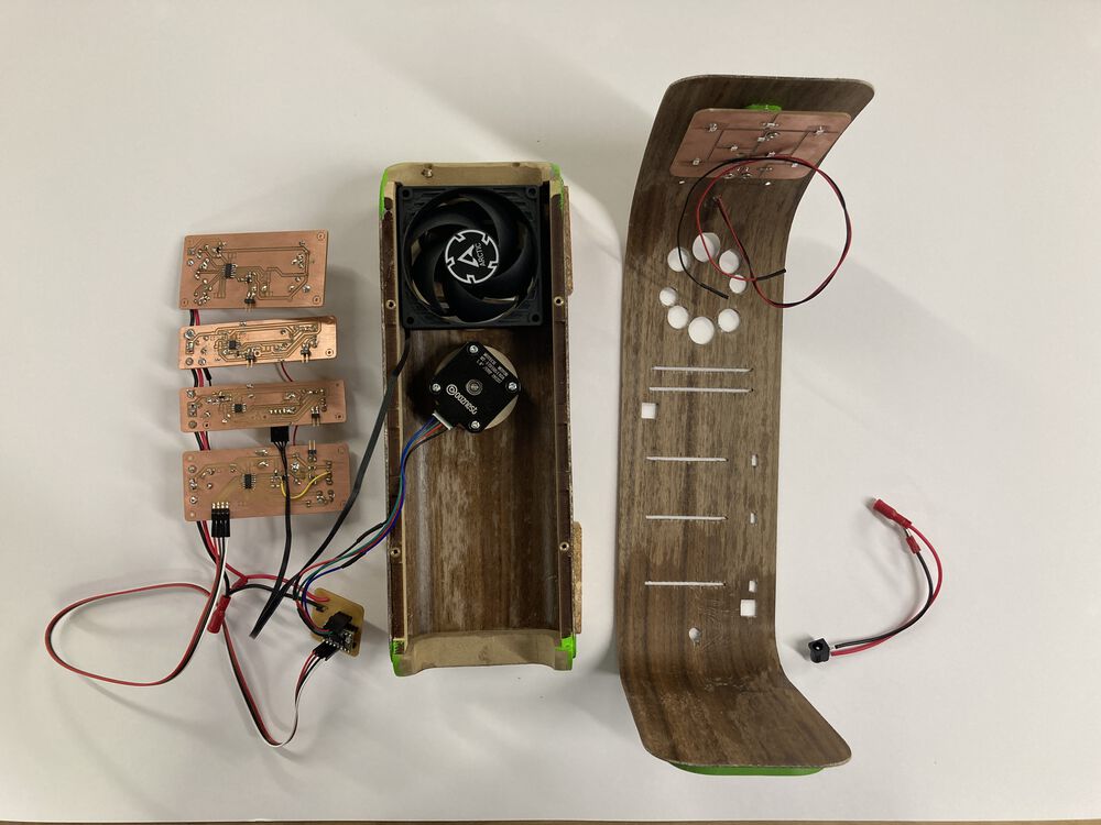
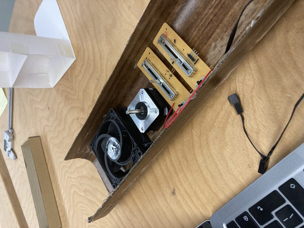
Install parts:
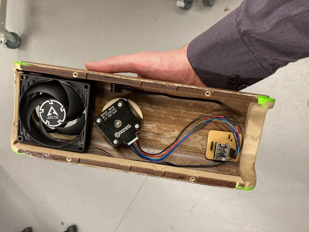
Packaging it all up:
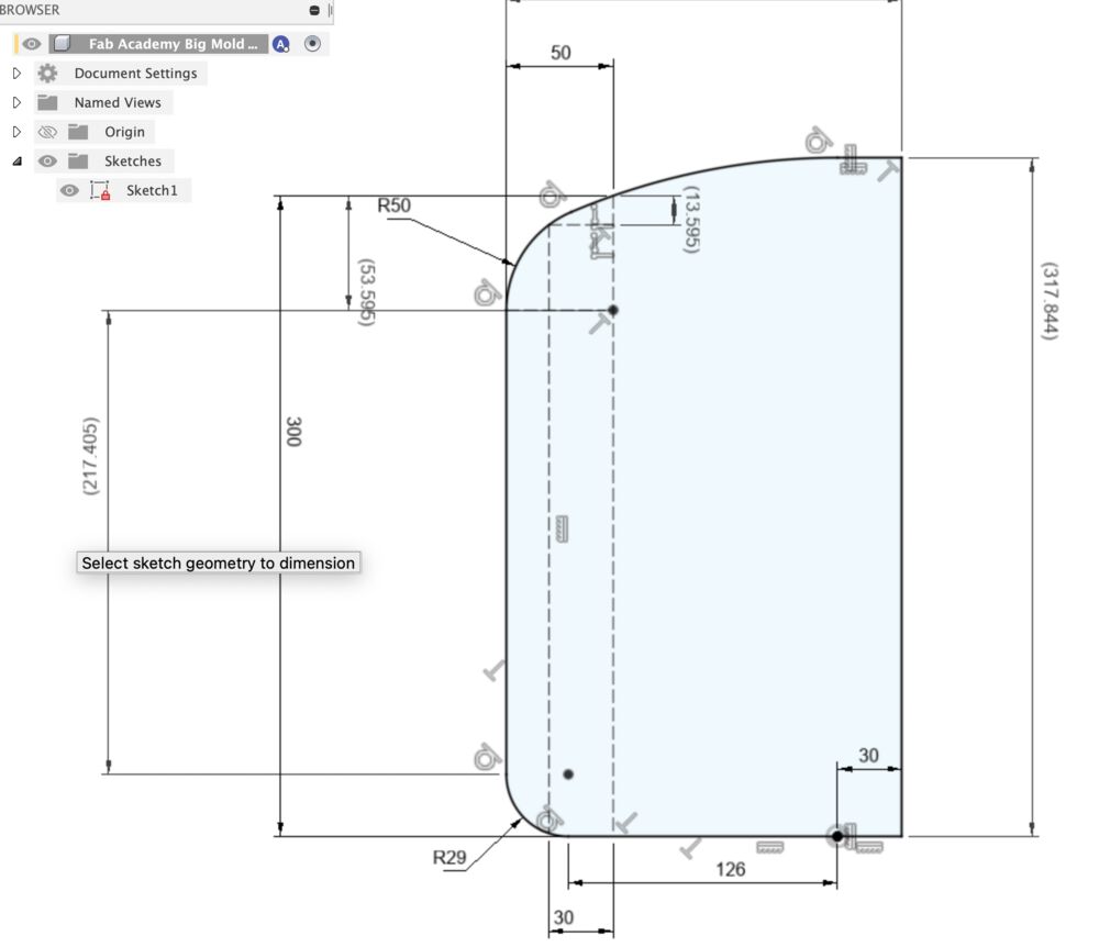
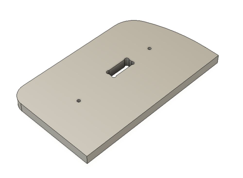
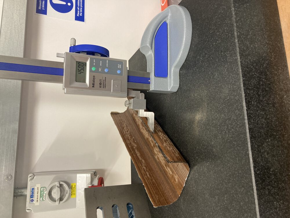
Last of the curves to be defined
Build progress II
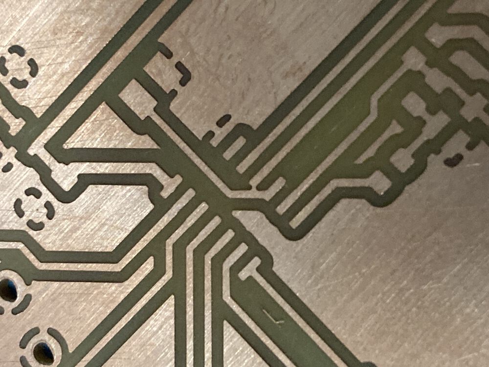
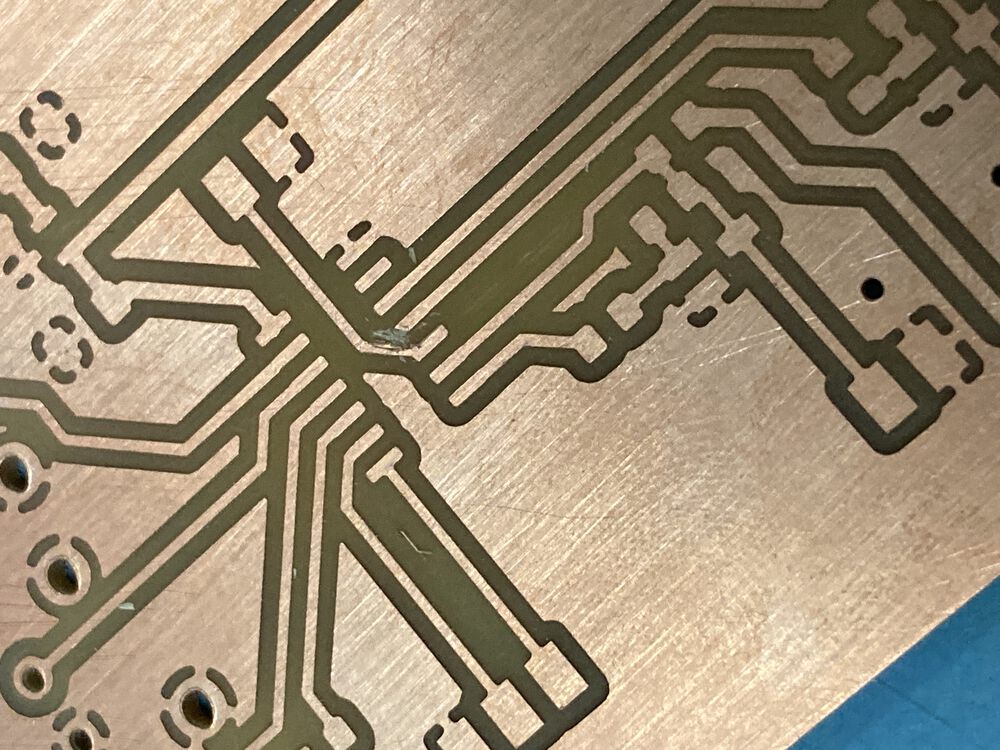
Build progress I
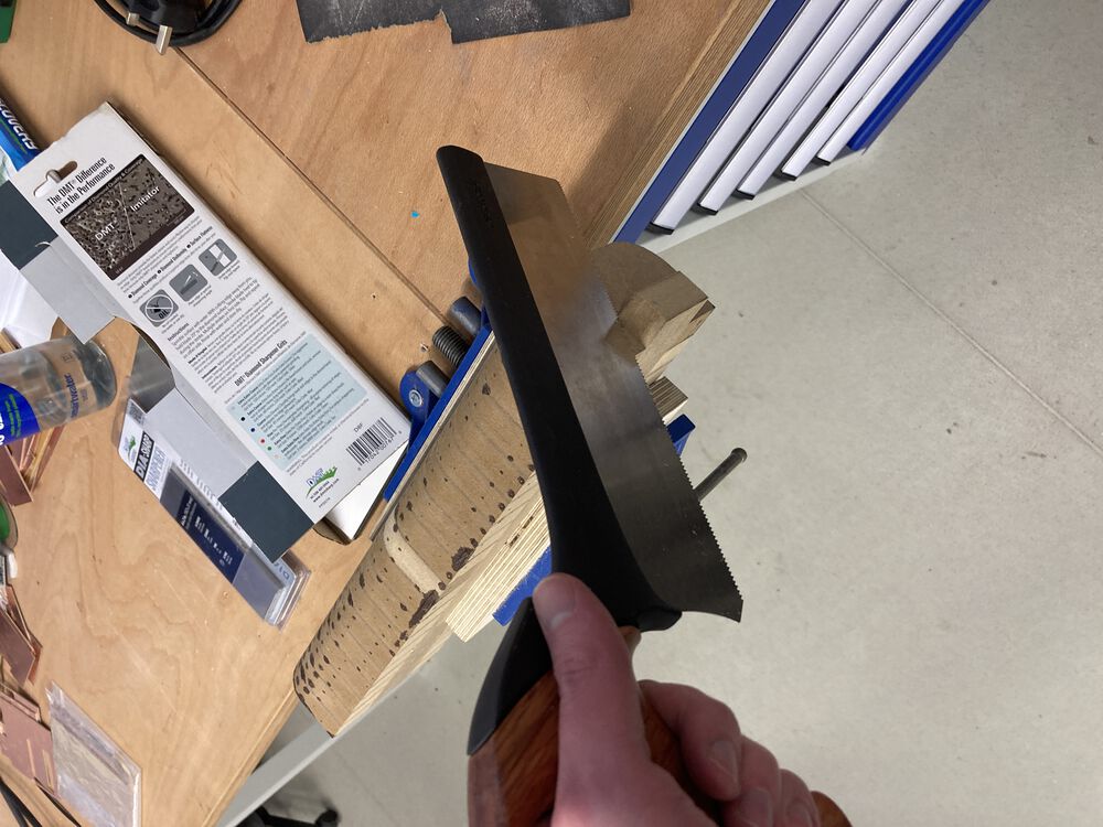
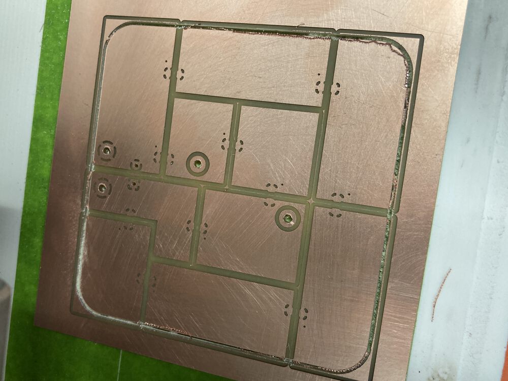
Amazing what a difference a sharp tool will make:
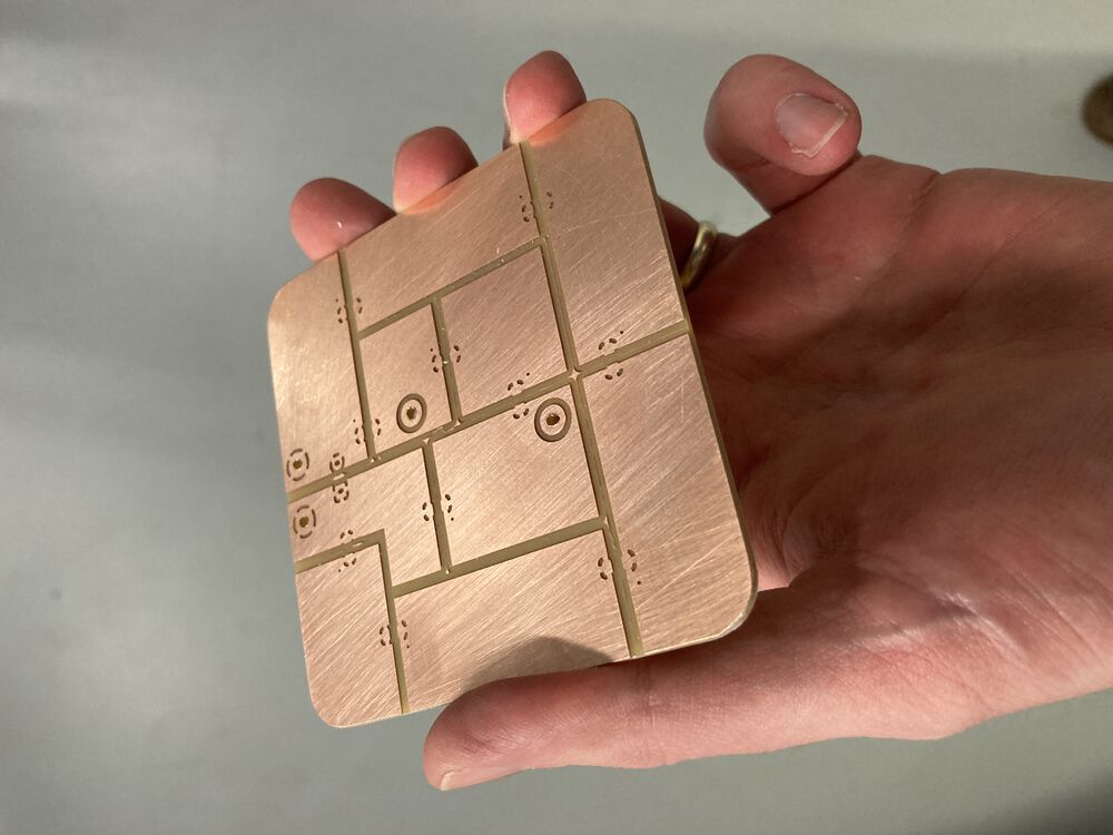
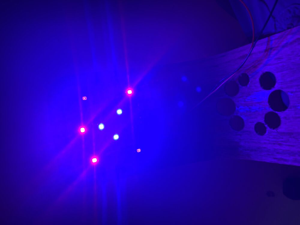
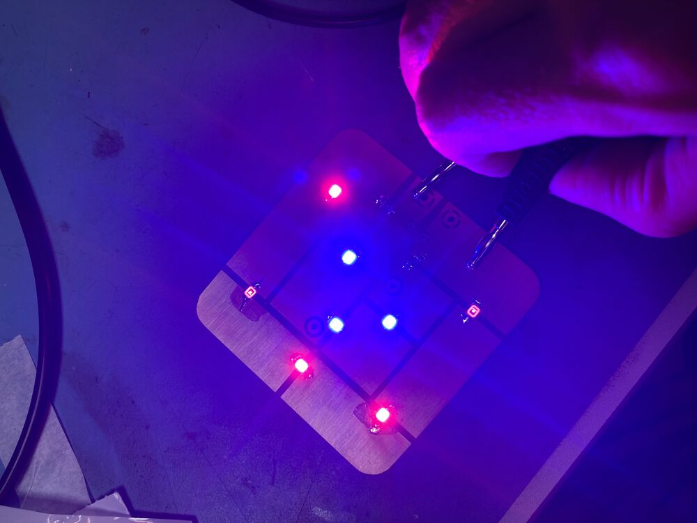
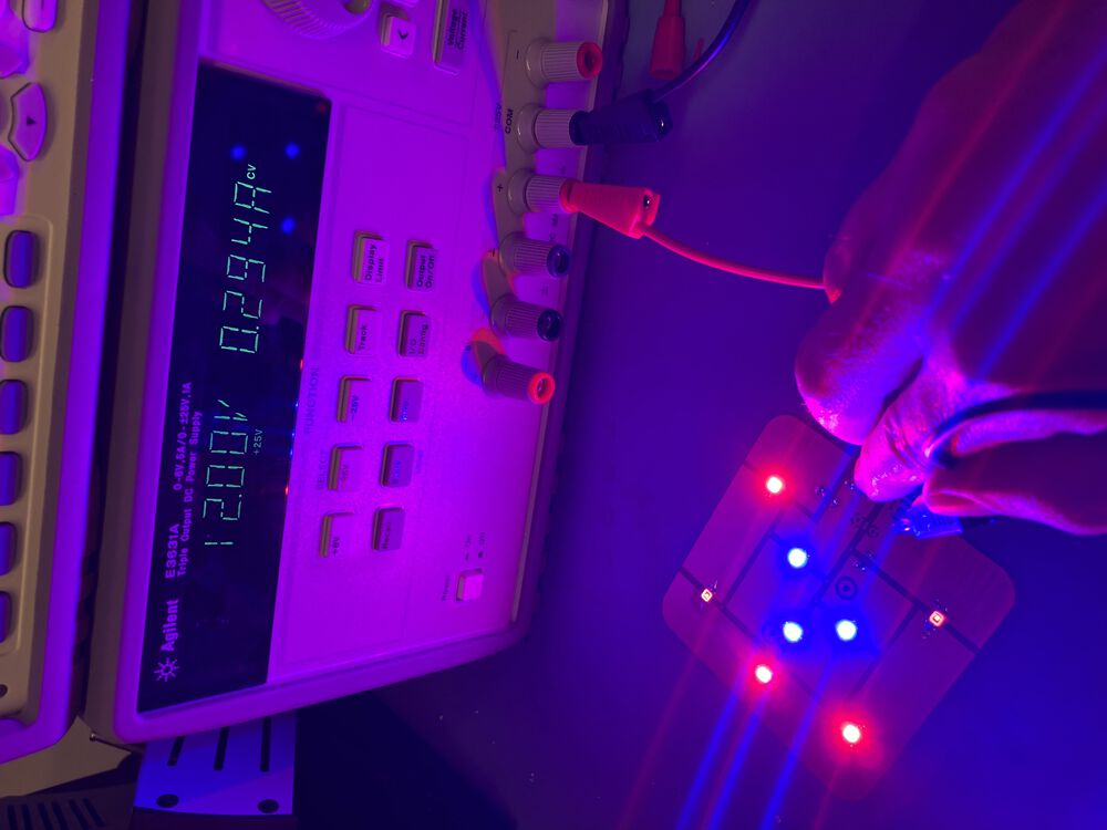
Panel works exactly as specified:
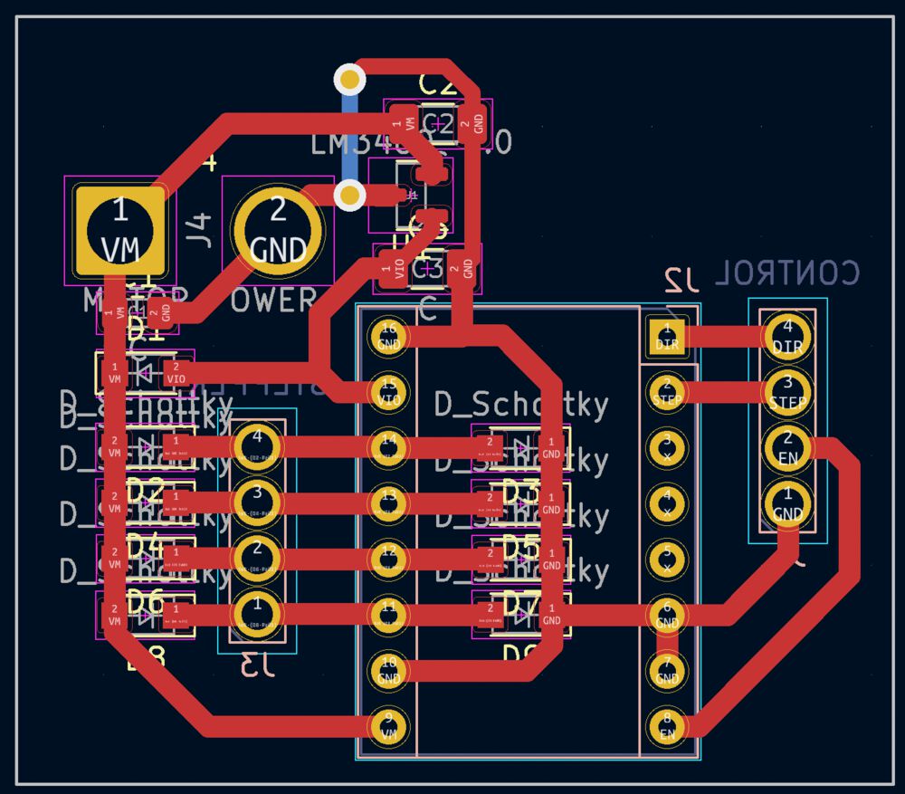
Error in pcb layout, not enough clearance here, need to set up some rules:
![]()
![]()
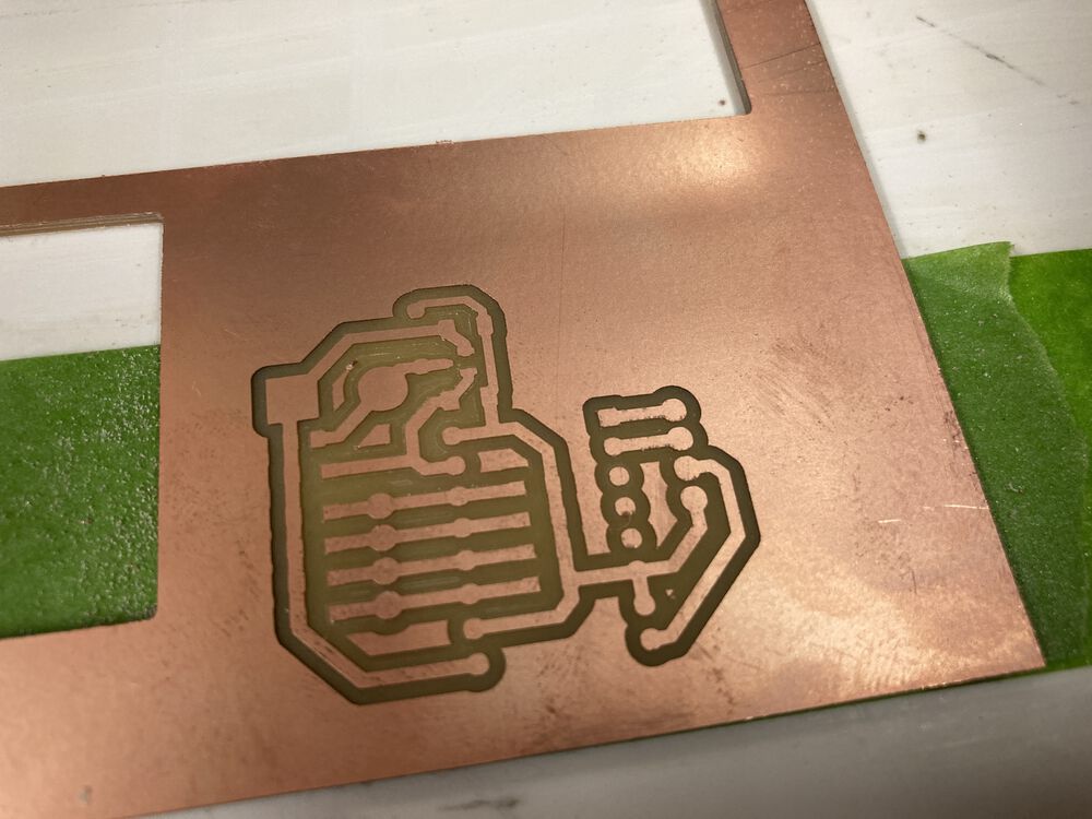
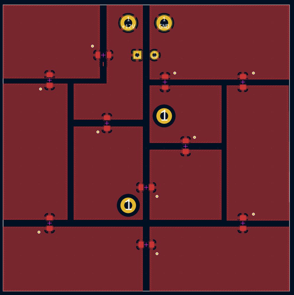
Another nice job from the mill, breakout for the stepper driver included protection cct:
Design notes, week starting 23rd May
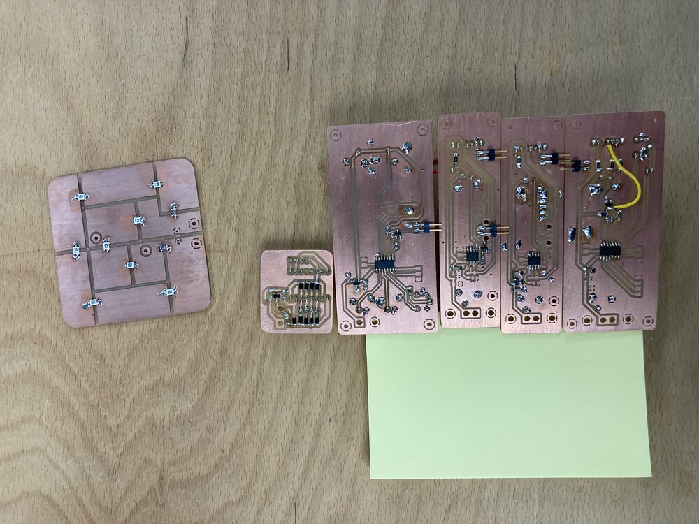
Final Circuit Designs
Pump Board:
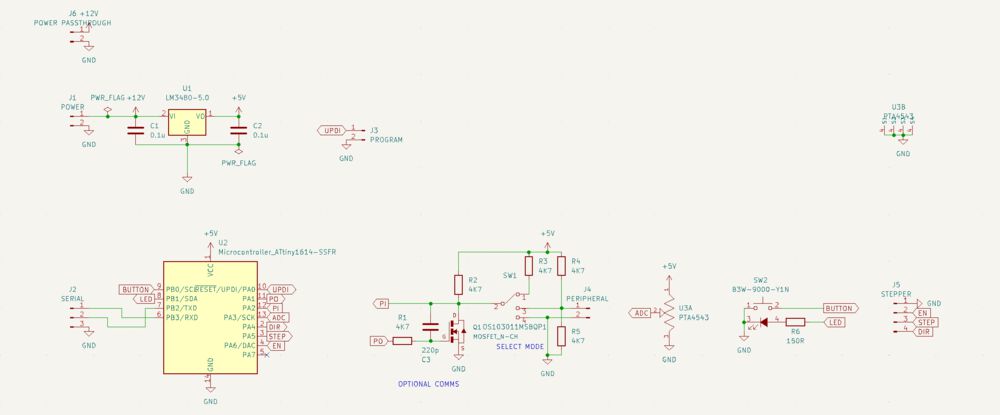
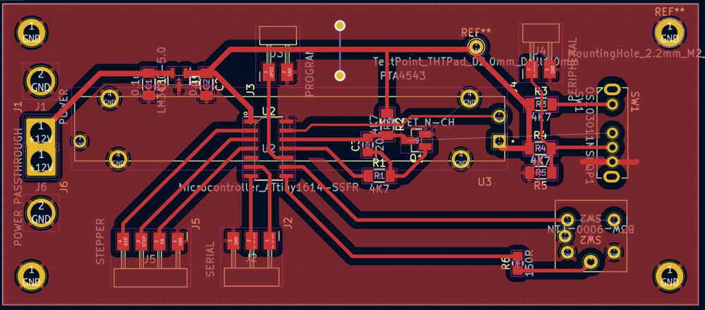
Timer Board:
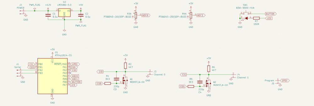
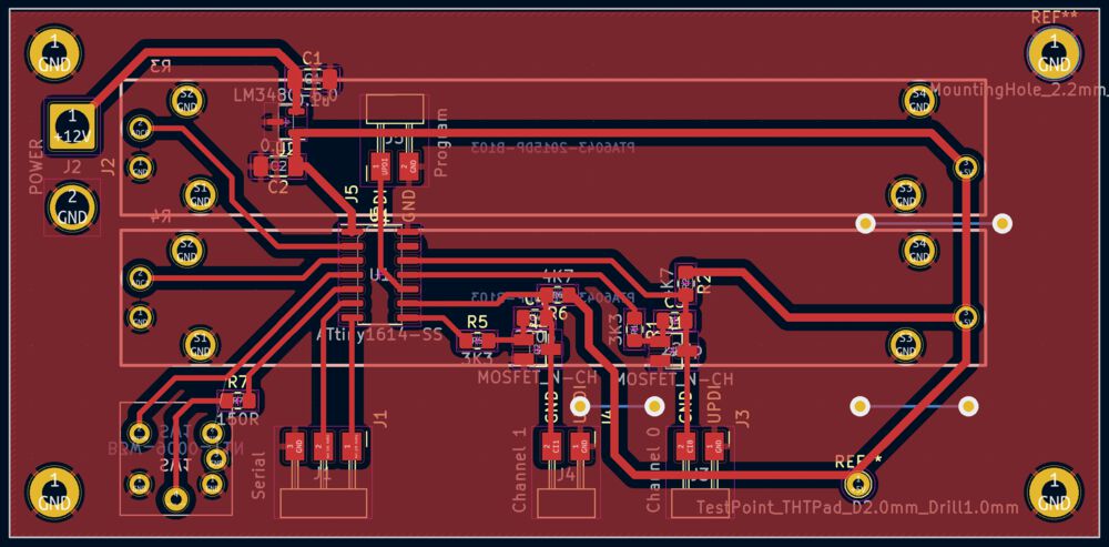
Dimmer for FAN/LED:
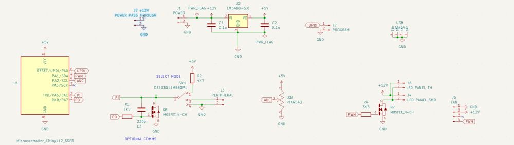
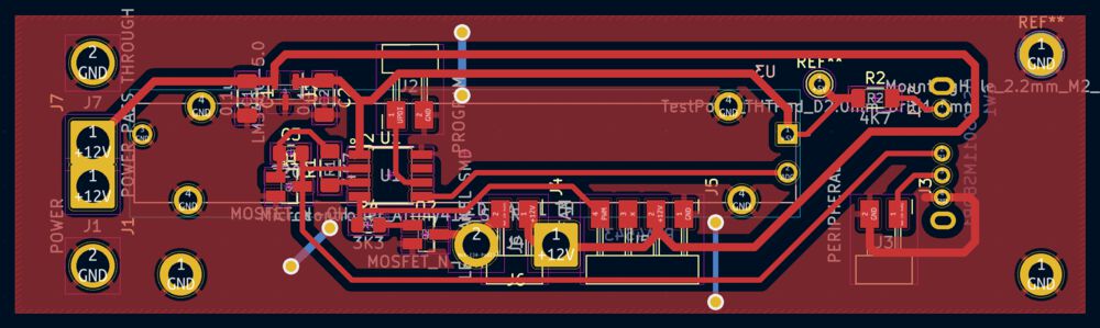
LED Panel:
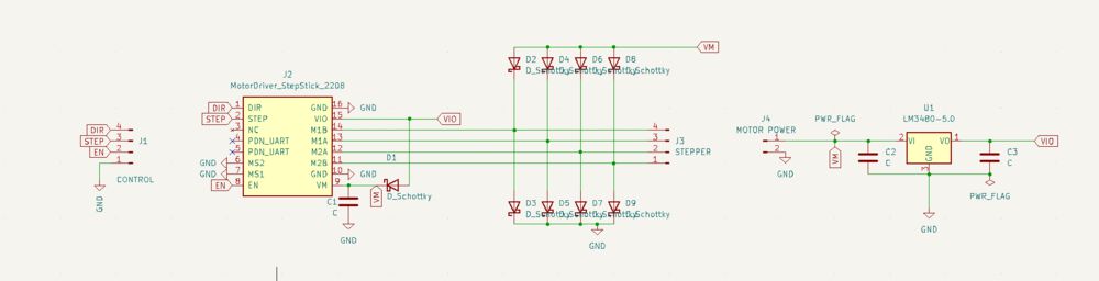
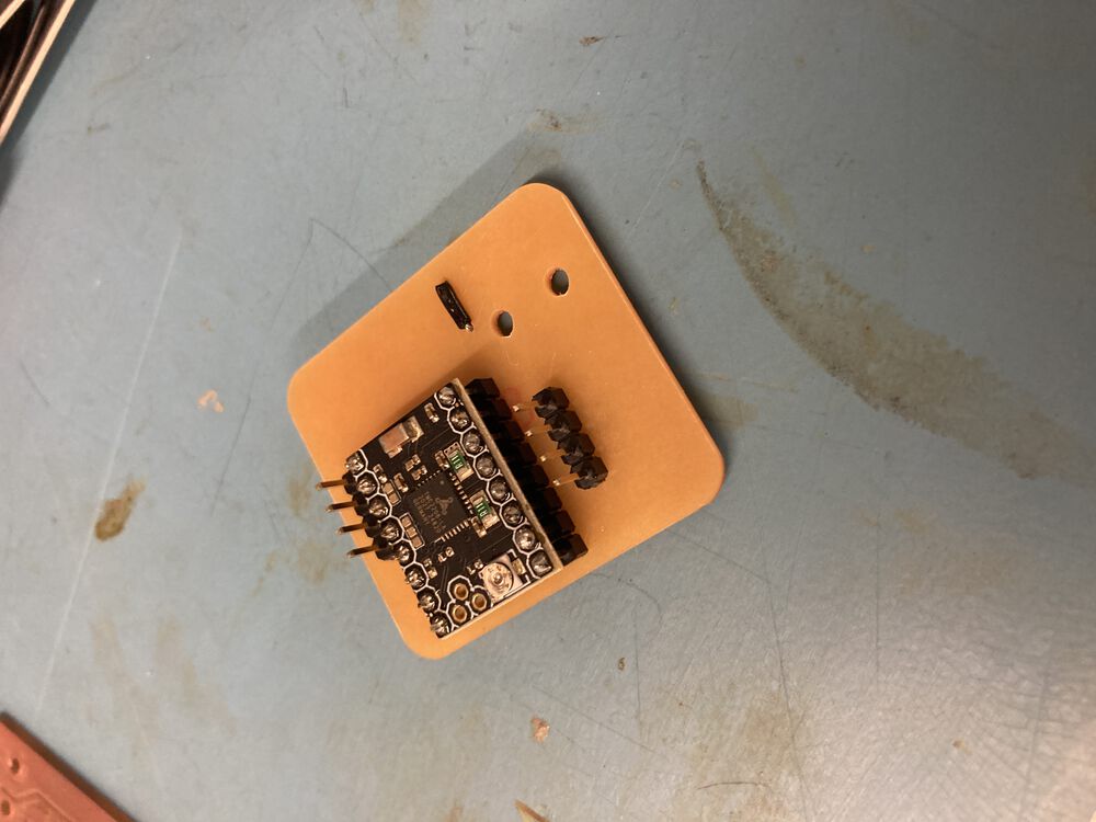
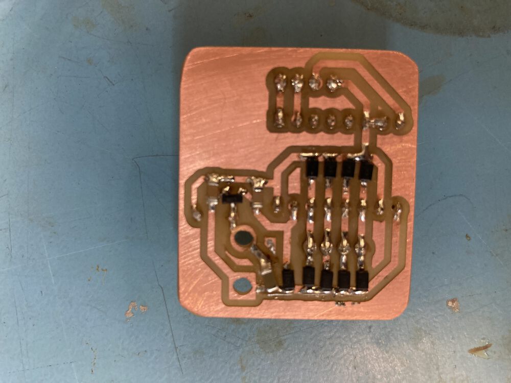
Stepper Breakout:
Some inspirations for distributed small scale.
(link working at time of writing)
reliable 1-wire littlebits Brooks Subsumption pocketQube PQ60 Interface
Design Inspiration
A walk in the park and further afield
Mock-up
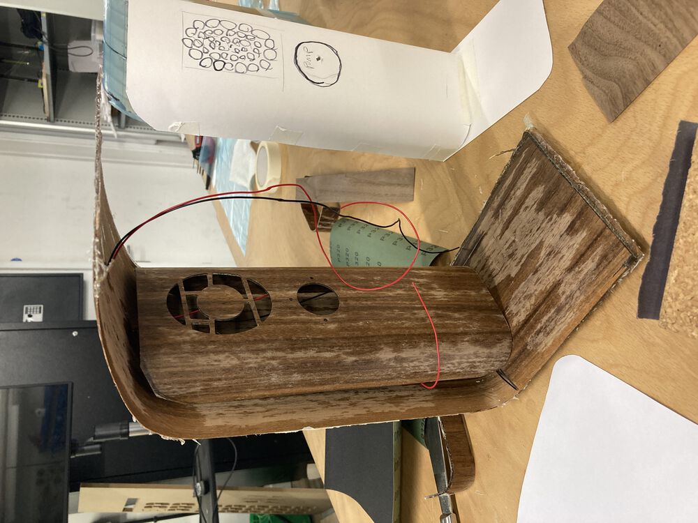
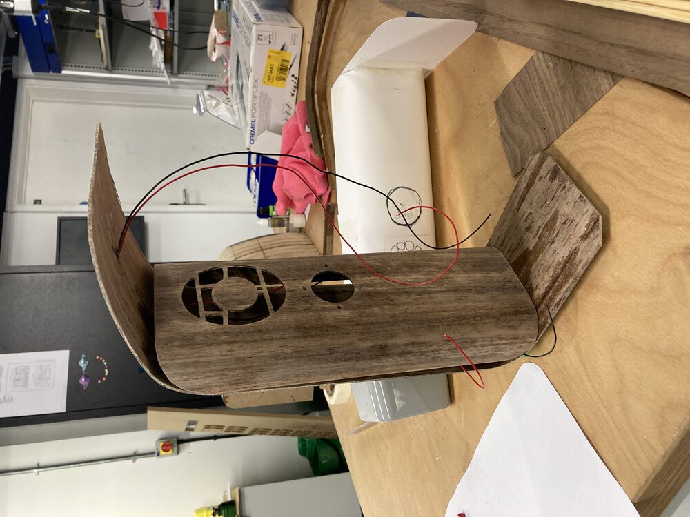
Profile of the curve is a mix of experimenting in card with the parts to be enclosed, then a bit of CAD for a set of consistent profiles and back to card to wrap up the fan and the pump motor.
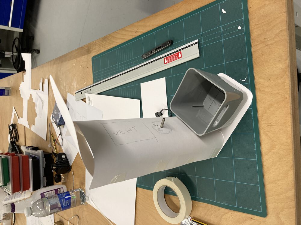
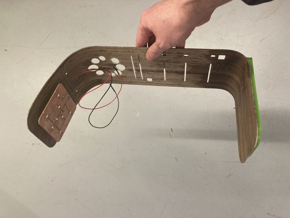
An attempt at defining the final form, plenty of room in the back for electronics. Foot so it doesn’t fall over. Sweep over the top to support the LED panel.
Architecture, some notes
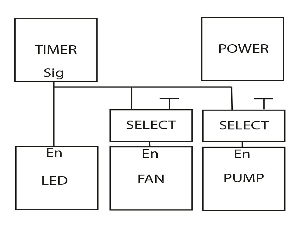
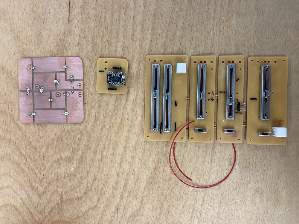
Above is the plan for the electronics. For an example of one of the completed parts see Output Devices week
As one of the goals of the project is to make a kit of parts I’ve been aiming to produce a collection of small single purpose boards. They, and their interconnections are illustrated above.
Simple signals
Inspired by little bits, I’ll be aiming to combine parts with very simple signals, in most cases a HIGH/LOW will do the trick.
In the example illustrated, the timer unit has a simple on/off signal that will directly drive the enable pin on the LED panel. The other drivers will have the ability to selectively get in sync with the LEDs or act independently, where the other enable input could either be, always on or always off. A three way toggle is also an option.
Specifications
POWER:
- 12V in, master switch, distributed to all other boards.
TIMER:
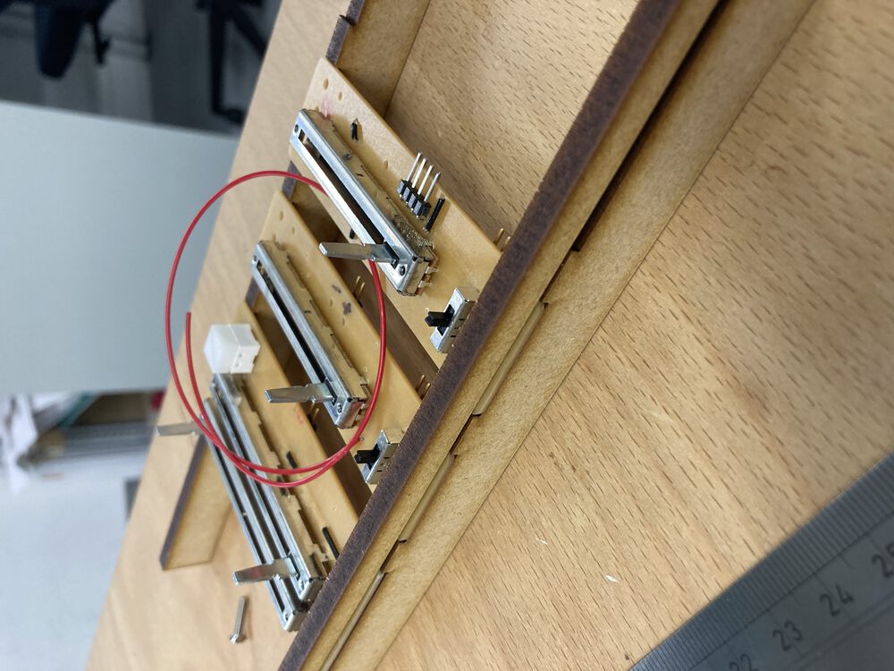
- Two slide pots, start and stop time
- Button
- Indicator LED
- Signal out
The intention is to have two sliders, one sets the on time the other the off time. They would also be used in combination with the button to set the clock, where a feedback/ack would be available with the LED. The output signal is used to drive the enable on other boards.
LED:
- Red and Blue horticulture LEDs
- 12V in
- En signal
- Slide pot for dimmer
FAN:
- 12V in
- En signal
- Slide pot to set speed
PUMP:
- 12V in
- En signal
- Slide pot to set pumping minutes/period. Water volume.
First project component complete
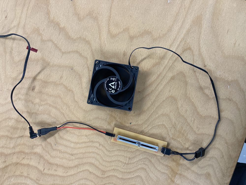
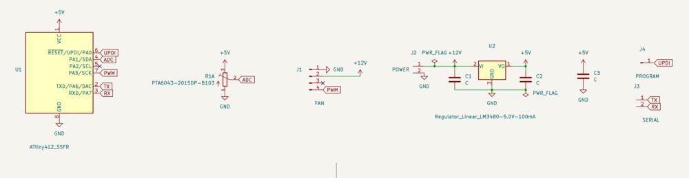
Simple fan controller
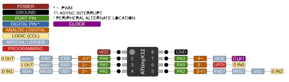
Using the ATTINY412 to read a Potentiometer and output a PWM suitable to drive a fan. 12V supply with local 5V regulation. Serial TX and RX broken out for potential use as a networked device. Probably use the megaTinyCore so check on the supported peripherals in that documentation.
This has been refined and used for Output Devices week
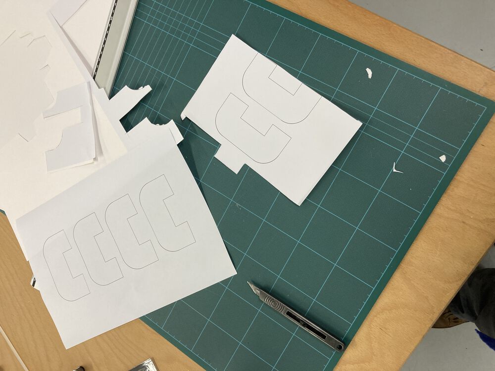
Iconography
Design some symbols that are representative of the functions of the system for language free labeling. Need symbols for light, water and air.
![]()
![]()
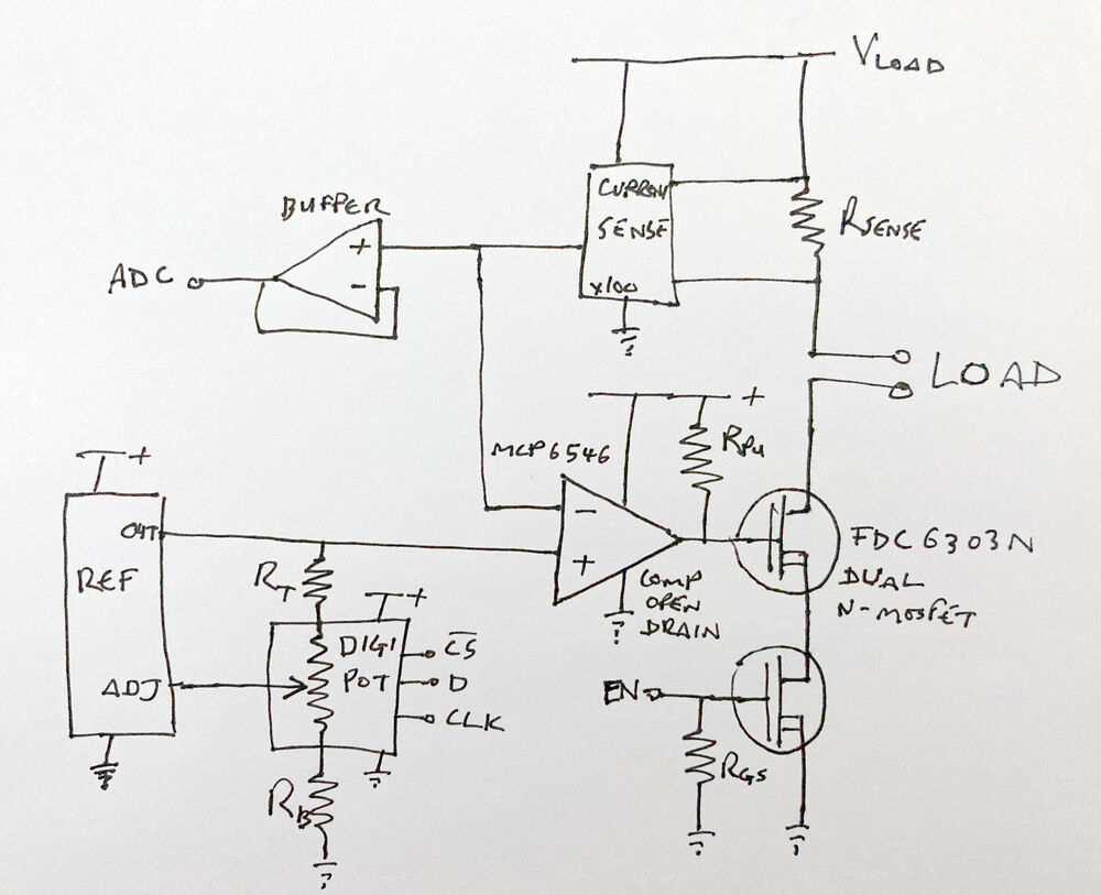
Design for a current source
It would be desirable to create a current source to drive the series chains of LED’s that will light up the plants.
Here we present an outline for a circuit that will be designed to supply a nominal 180mA at full brightness and capable of dimming the LEDs.
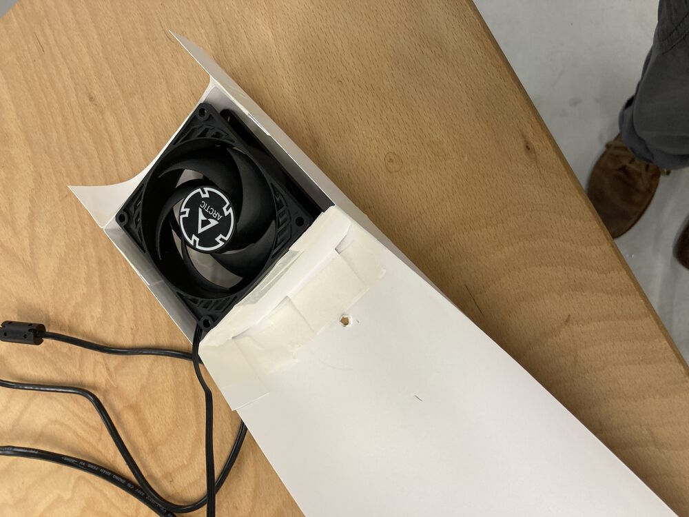
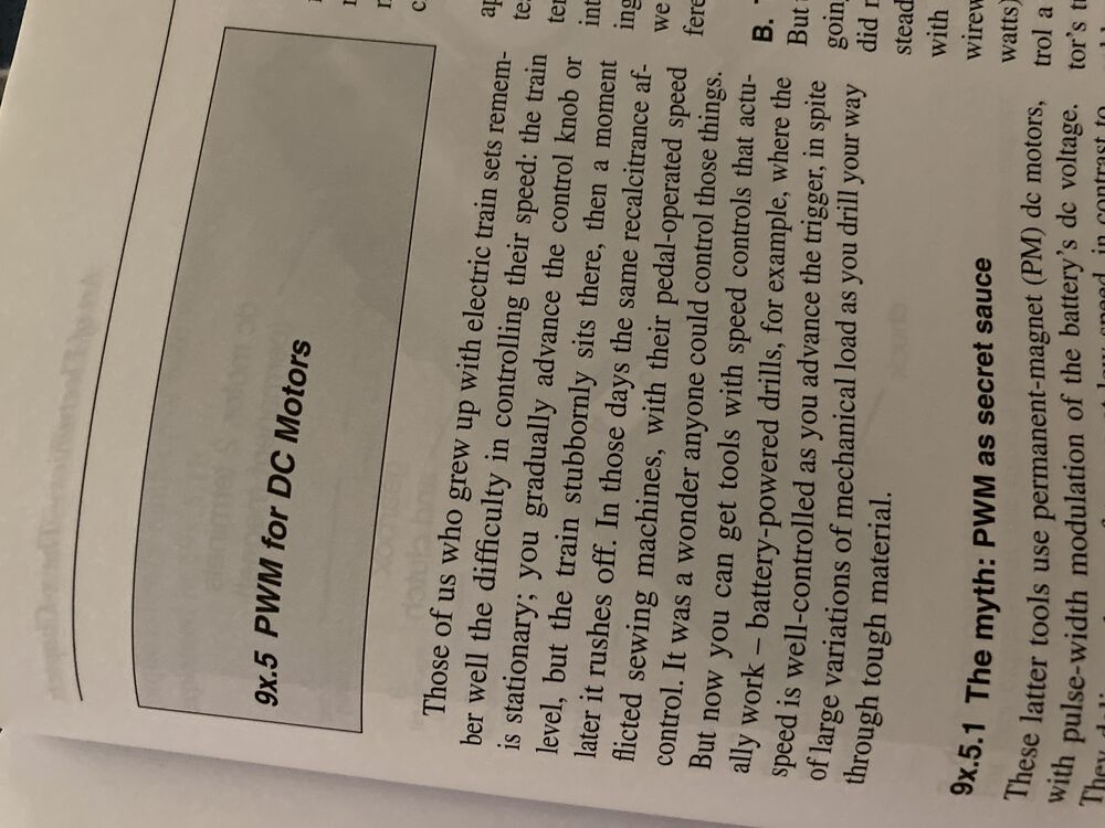
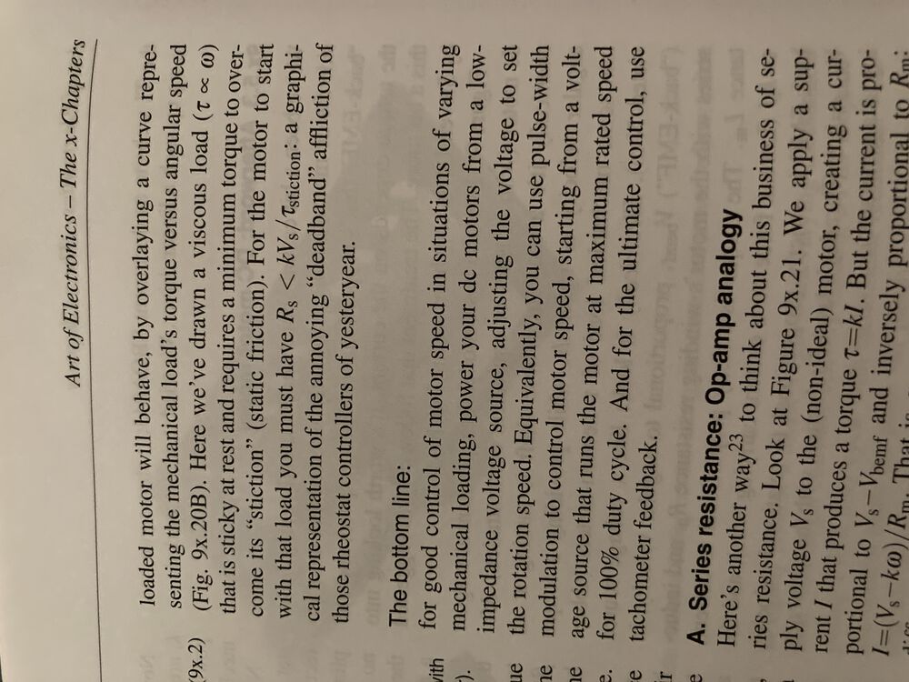
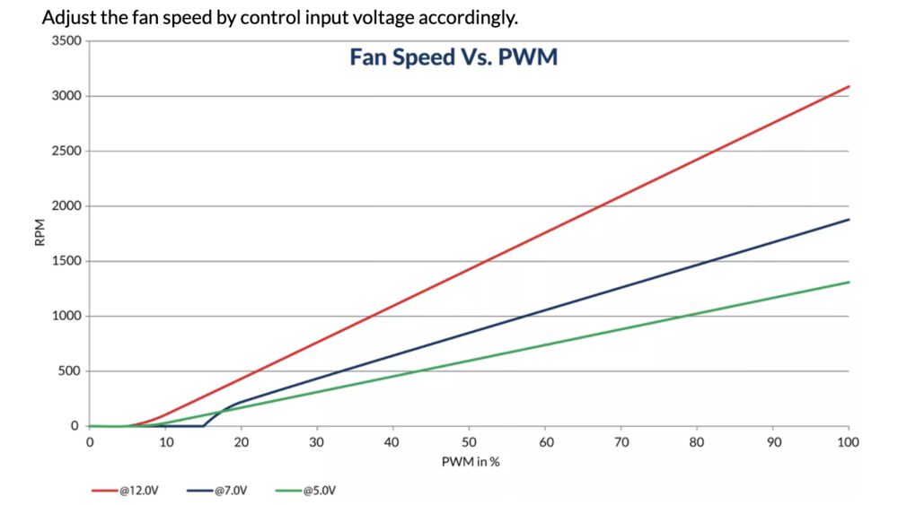
Running a FAN
For the project I started looking at how to drive the fan. With a design for a current source for the LEDs being sketched I was thinking of designing a variable voltage supply to run the fan. But reading up in the X Chapters I discovered that there was little benefit in the complexity over plain old PWM. So that’s what we’ll do.
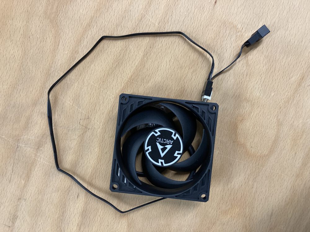

The manufacturer provides a spec for the PWM signal that the fan takes:
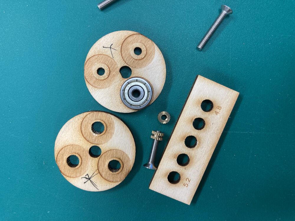
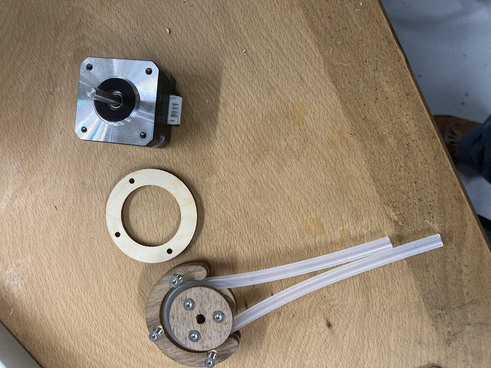
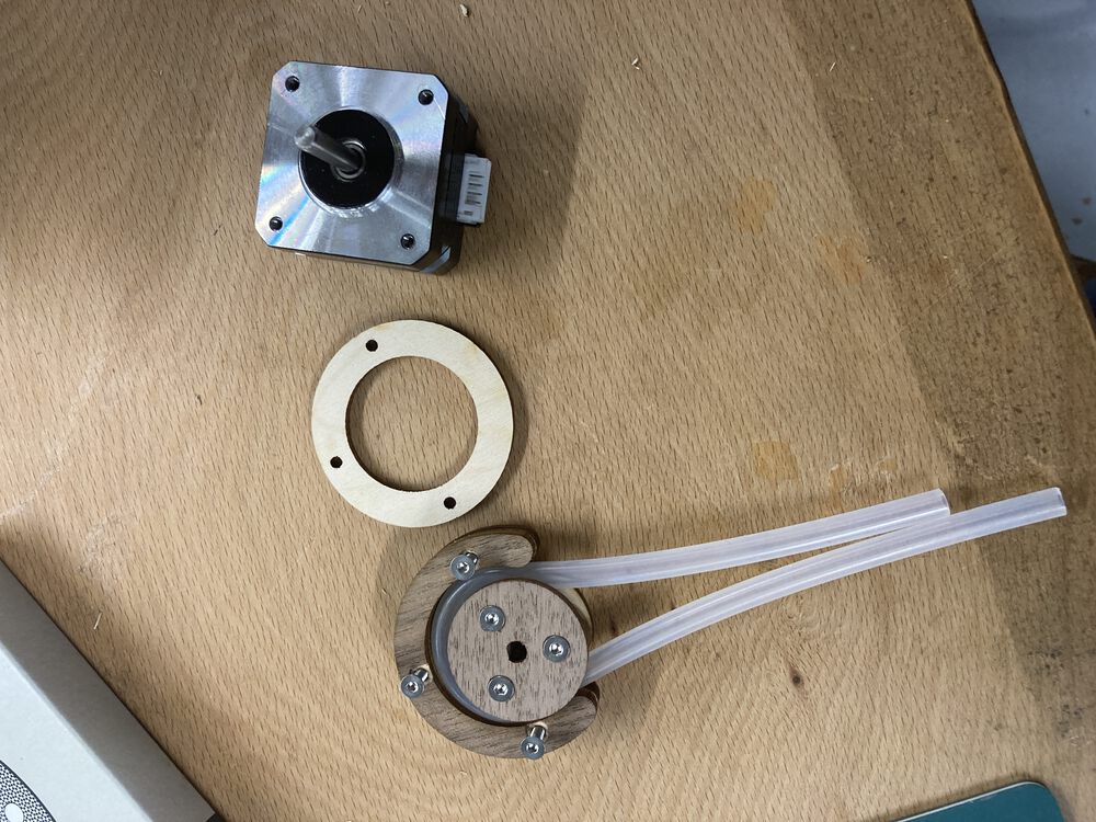
A Prototype Pump
Initial design goals. Can we use the laser rather than 3D printing the parts? Can we constrain the outline of the pump to coincide with the size of the motor?
Full disclosure I designed the pump on paper and purchased all the components. When it came to using the laser cutter I needed a task to use as a teaching exercise, so I got some students to hemp me implement the design.
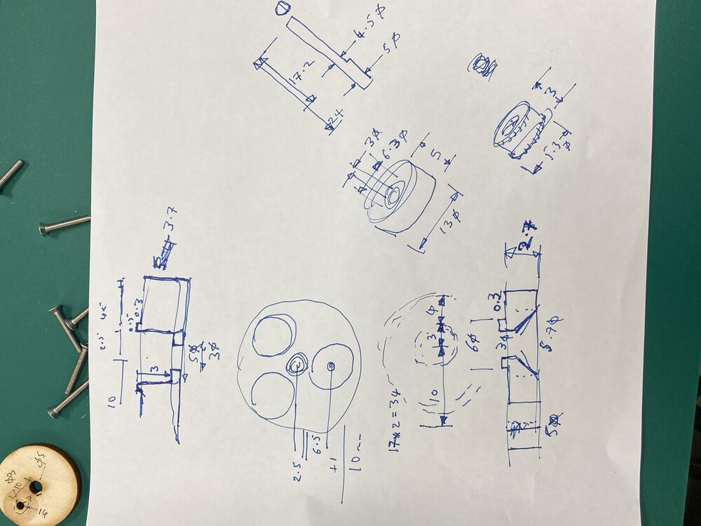
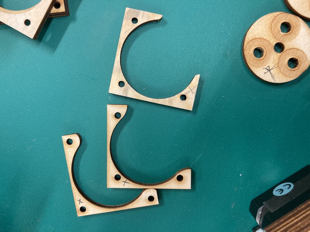
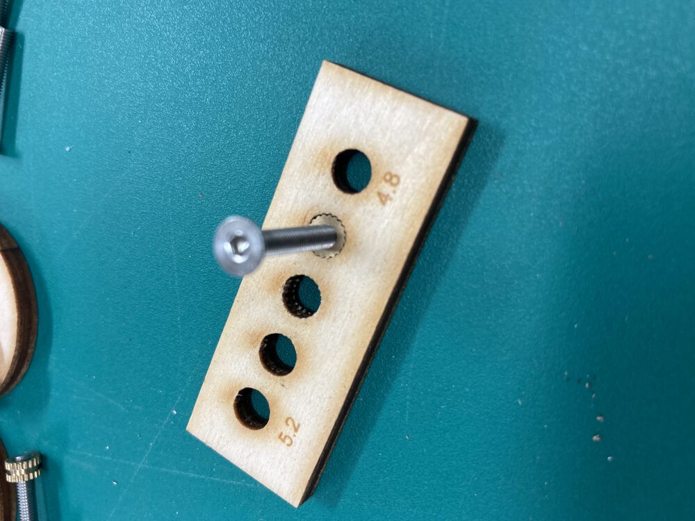
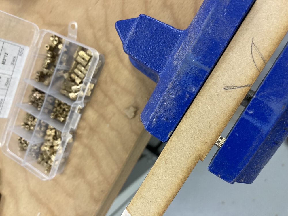
Notable features in the deign. Uses thread inserts in the bottom of the rotor assembly. Rotor assembly parts have relief engraved in to clear moving bearing surfaces.