
Individual
1. Design and produce something with a digital fabrication process (incorporating computer-aided design and manufacturing) not covered in another assignment, documenting the requirements that your assignment meets, and including everything necessary to reproduce it.
Plan for the week
I will be using ZUND for this week where i will be using it to make a cardboard furniture. My main motive is to make a one board furniture, i.e one board table which is easy to fold and unfold and would be easy to transport as well as lightweight. Thought it might not be durable as wood but is cheaper and easy to transport and light weight.
The process this cant be done by other machine that has been used in previous weeks is creasing. Here I will be using creasing to make a reference crease to fold the flaps or sides to fold it down to the table.
A 90 degree V-cut can be used in this process as well but according to my instructures, Rahul and Jogin, they recommended it might be easy to fold but strength-wise it would be weaker hence to move with the creasing tool. Then I tried to understand the general background about the machine and what it can do and how it can be used.
About the machine
Zund G-3 L-2500
Manufacturer: Zund
Model: G3 L-2500
Specifications: Repeatability +/- 0.03 mm, position accuracy +/- 0.1 mm/m, working area 1800 mm x 2500 mm, high speed router 3.6kW 50,000 rpm
Applications: A range of modules provide the capability to cut, score, crease and mill. Use cases include origami/kirigami for rapid cutting-and-folding of structures with tunable properties, two sided milling for press fit furniture and cutting of carbon fiber, fabric for composite lay ups.
The ZUND is modular cutting system that can be adapted and used to cut, route and draw on a range of materials. With interchangeable modules, tools and blades, the ZUND can be configured to cut vinyl, fabric, leather, cardboard, foam core, rubber and many more!
Software requirement
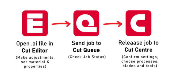
Cutter editor, Cut queue, Cut center, Cut Manager
Tools:
There are several different types of tools that can be used with the Zund Cutting System.
Cutting
1. Electric Oscillating Tool – EOT
2. Power Rotary Tool – PRT
3. Electric Oscillating Tool – EOT-250
4. Driven Rotary Tool – DRT
5. Pneumatic Oscillating Tool – POT
6. Wheel Knife Tool – WKT
7. Universal Cutting Tool – UCT
8. Passepartout Tool – PPT
9. Scoring Cutting Tool – SCT
10. Laser Module – LM 100W
11. V-Cut Tool – VCT
Kiss-Cutting
1. Kiss-Cut Module – KCM-S
2. Kiss-Cut Tool – KCT
Creasing
1. Creasing Tool Type 1 – CTT1
2. Creasing Tool Type 2 – CTT2
3. Creasing Tool Type 3 – CTT3
Perforating
1. Perforating Tool Type 1 – PTT1
Routing & engraving
1. Universal Routing Tool – URT
2. Automatic Router Bit Changer – ARC
Punching
1. Punch Modules – PUM
Marking & plotting
1. Marker Modules – MAM
2. Universal Drawing Tool – UDT
3. Raster Braille Tool – RBT
For manual please refer this link.
To know detail about each tool please follow this link.
For workflow please refer this link.
For tutorial please follow this link.
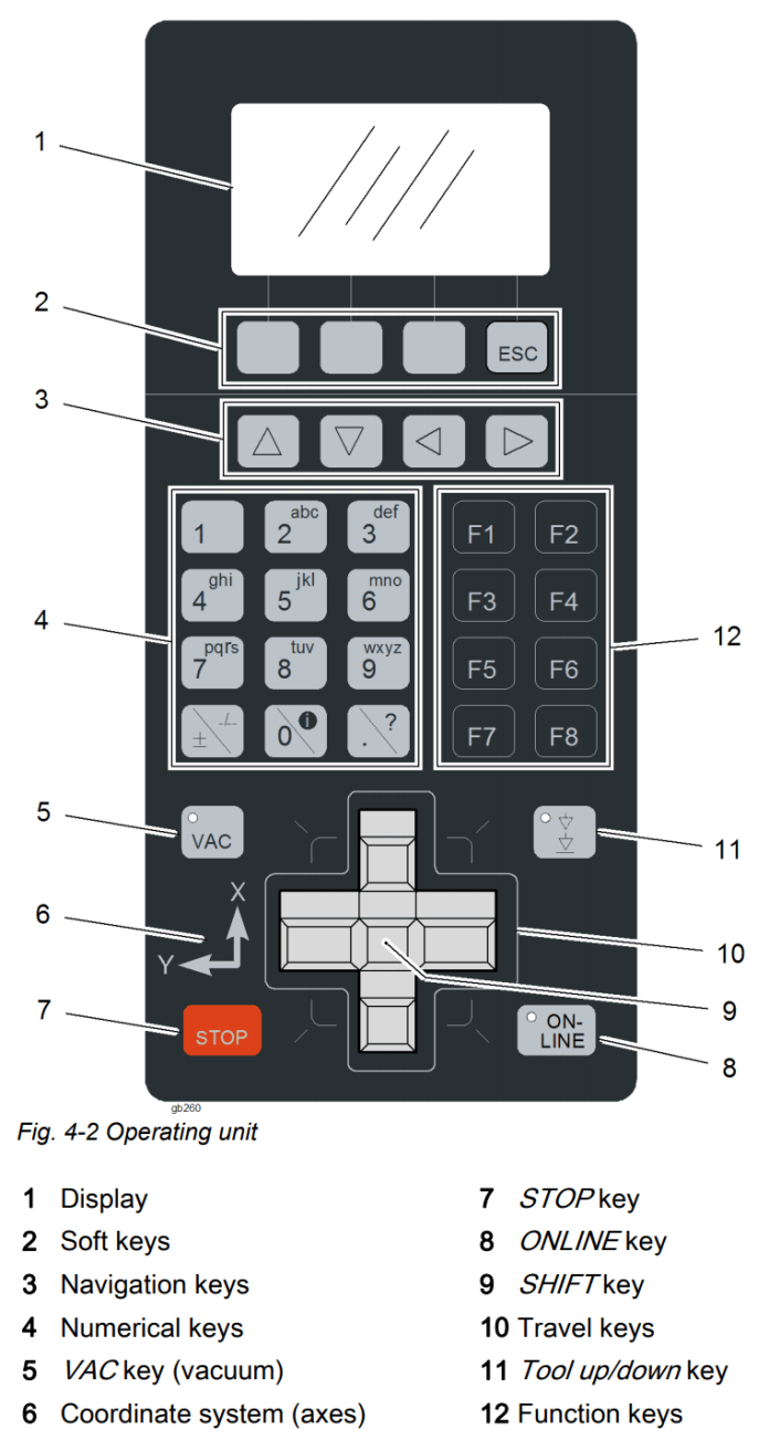
Controls
The console directly controls the cutter without going through the software. The console is used primarily for performing tool changes, turning the machine on/off and switching between online and offline mode.
The gantry can be manually controlled by the travel keys and moved rapidly by holding the 'shift' key.
The Vacuum can be toggled on and off by pressing the 'shift' key and 'VAC' key.
Pressing any of the travel keys of 'STOP' during a cutting operation will pause the job and raise the tool until the 'Online' button is pressed, resuming the job.
Light Barriers & Emergency Stop
The Zund has safety features to prevent injury during operation. The main feature is a series of 'light barriers' that are projected from one end of the gantry to the other on the front and back side of the cutter. If these beams are broken by someone reaching into the operating area, or if a piece of stock lifts up unexpectedly, the cutter will immediately stop operation. To continue the operation after everything is cleared from the table, press 'OK' then 'Online' to continue the cut from where it stopped.
While the light barriers are a soft stop, the red emergency stop buttons are a hard stop. When the emergency stop is pressed the operation immediately stops, cancels the current job and disengages the tools. To continue from an emergency stop the button must be twisted to be released, then follow the instructions on screen. The tools will re-engage and require initialisation and the job will need to be restarted from the PC.
If something begins to go wrong during the cut, such as the stock moves unexpectedly, the operation can be paused by pressing any of the grey directional buttons on the console or 'online'. The job can then be resumed by pressing 'online' once the issue is resolved.
Navigating Cut Center
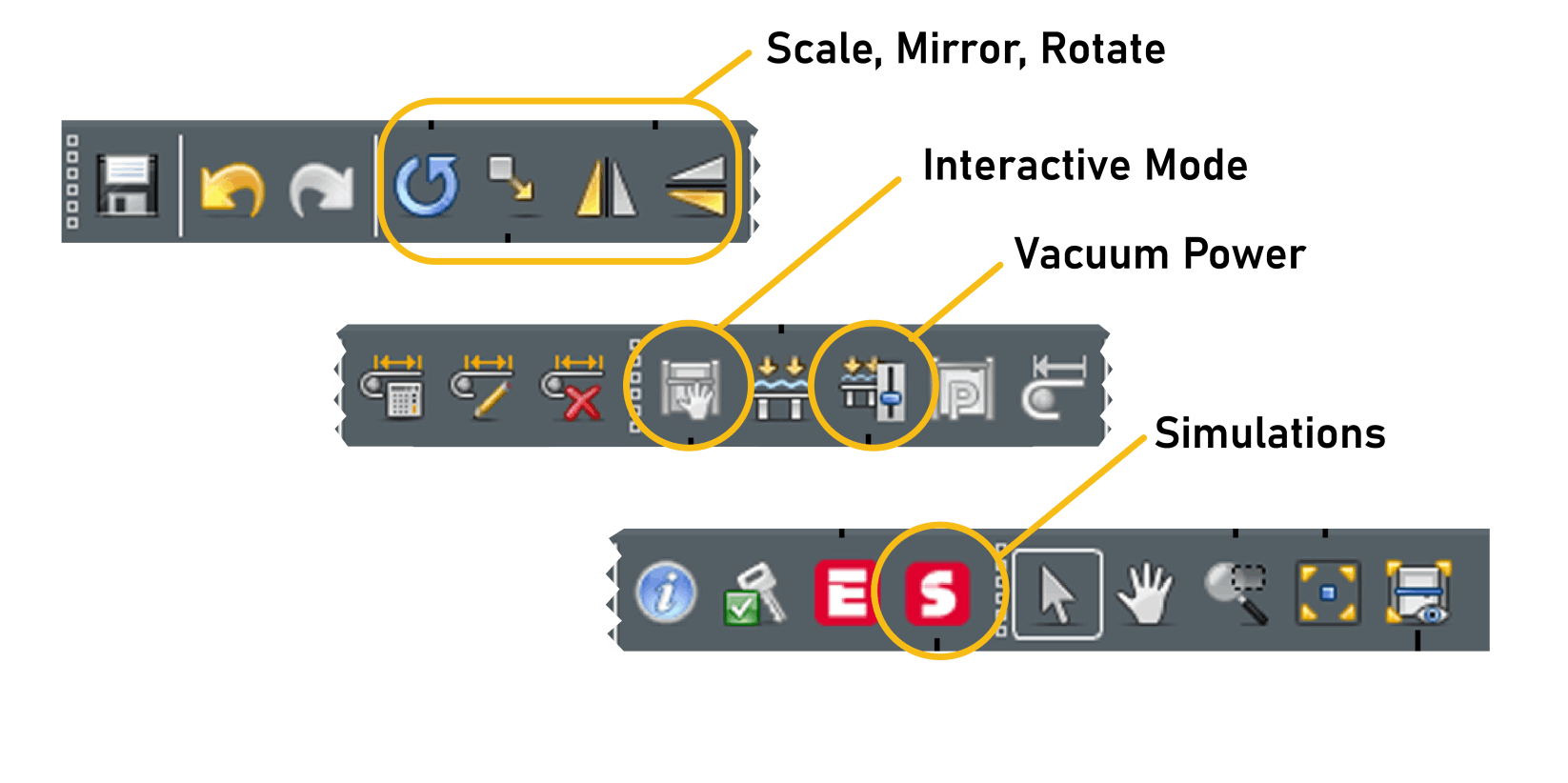
Rotate, Scale, Offset and Mirror - allows adjustments to the objects before cutting
Interactive Mode - Zund must be 'online' to activate interactive mode. Can control placement of cutters and set reference points from computer.
Vacuum Power - Adjusts vacuum strength and can turn vacuum on/off.
Simulations - Starts a simulation of job before it cuts/draws. Used to check material placement and ensure tool paths are correct
Operation Parameters within Cut Center
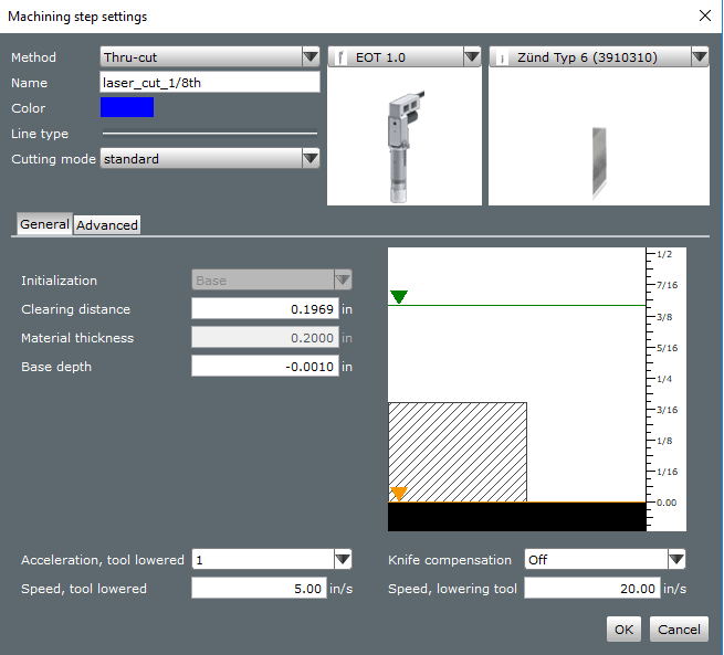
1. Method: The type of operation to be performed. Each material has a set of available operations depending on its characteristics.
2. Name: What the layer will appear as on the right hand side of the screen.
Color: The color the layer will render as on the screen.
3. Line type: Whether the operation will perform along a solid, dotted, or dashed line.
4. Cutting mode: Always set to standard.
5. Tool selection: Drop down menu will allow the selection of the tool to be used during the operation, if multiple are allowed.
6. Tool insert selection: Select the tool insert (blade or bit) to be used during the operation.
7. Initialization: Where the tool will register height from. Alway set to base.
8. Clearing distance: How high above the top of the material the tool will retract to travel. Does not need to be adjusted from default.
9. Material thickness: Current thickness of the material. Cannot be altered through this window, needs to be set in the material selection window.
10. Base depth: How deep relative to the table the material will cut. Should never be more than +/-.005. Adjust in small increments (+/-.002) if blade is not cutting all the way through the stock.
11. Multi. pass max. depth: The most stepdown the router will perform on a single layer. Should not exceed .0500in.
12. Multi. pass last depth: The depth of the final routing layer. If using bridges, should be at least .0200in, as bridges are formed from this layer.
13. Machining depth: The specified depth for engraving operations.
14. Score depth: The specified depth of a score, either in inches or percentage of material thickness.
15. Acceleration, tool lowered: The maximum acceleration the tool will travel while cutting the material, from 1-4.
Speed, tool lowered: The maximum speed the tool will travel while cutting the material. Slow down for a cleaner cut in most materials.
3D design
I am designing the table can be assembled on site easily, it should very easy to move it unfolded. I am aiming for reduced weight and satisfactory strength for my product. This was it will be easy to transport as well as light weight and also have the functionality to it.
The table that I am aiming is 3 ft (L) X 2.5ft (B) X 2.5ft (H) but but depend upon the material available. I will make it parametric which i can tune it after i unfold it in the CAD and checking material size.
[Update]: the final table will be of dimension 2 ft (L) X 1.5ft (B) X 2.3ft (H)
Modeling
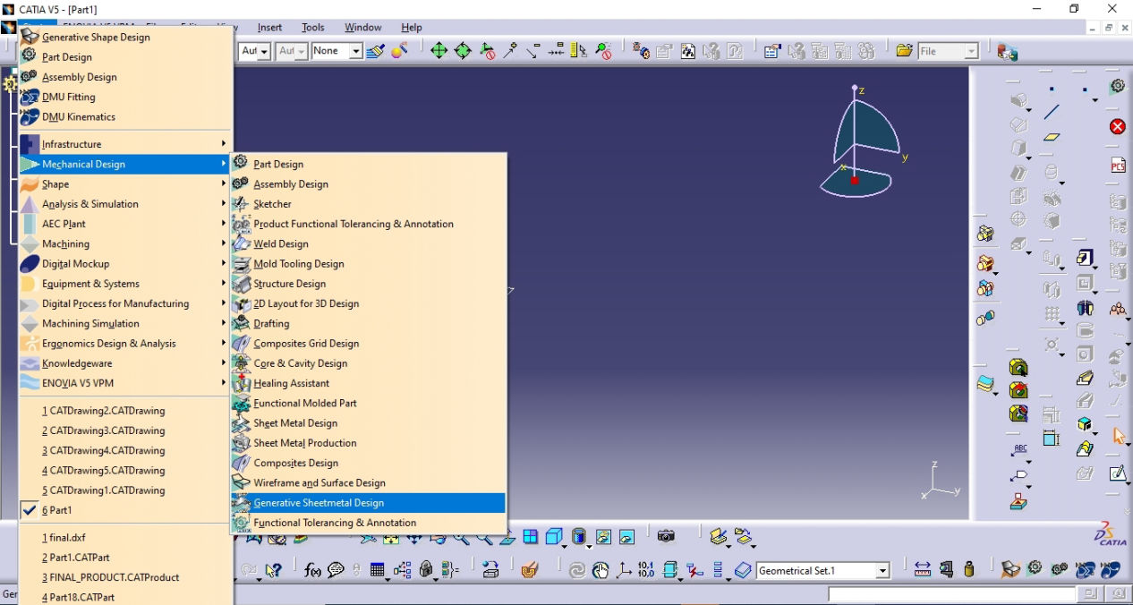
As the cardboard resembles resembles the sheet metal design, Sheet metal workbench is opened in CATIA. There are some steps which you can follow
First you have to go to the Generative sheet metal design workbench
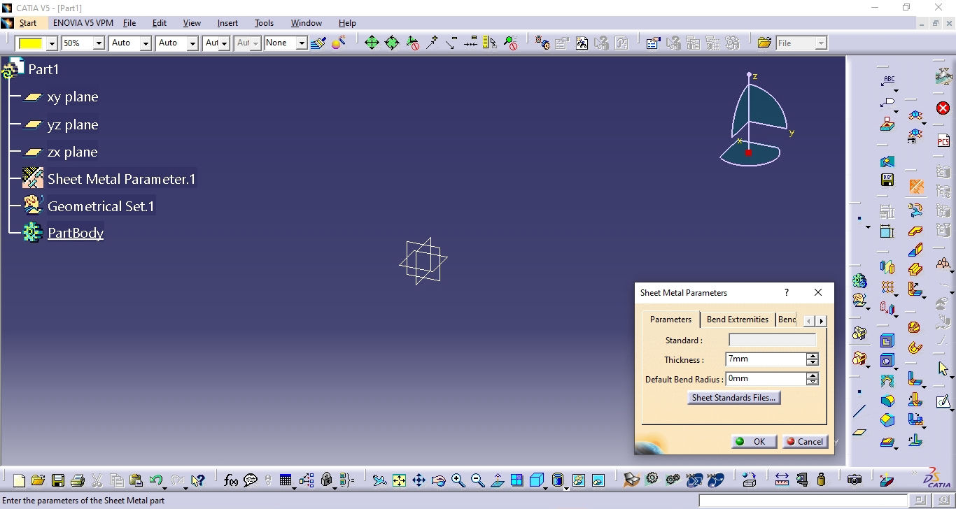
Then the first thing you need to do is set the parameters for the sheet. Here I am using 7mm thick BC flute cardboard. Since, I will be using creasing tool, I will be keeping the bending radius zero to make it as much close as possible.
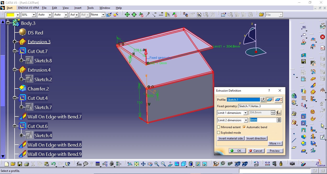
One way that will be easy while doing sheet metal design is that, you can sketch your basic main section and then use that shape to extrude. Here I have used the side section which is the basic shape for my design. As I said earlier in the parametric design in computer controlled cutting week, it is very easy for modeling and designing if you find your minimum basic shape on which boolean function can be used to make it full. Hence I did like this.
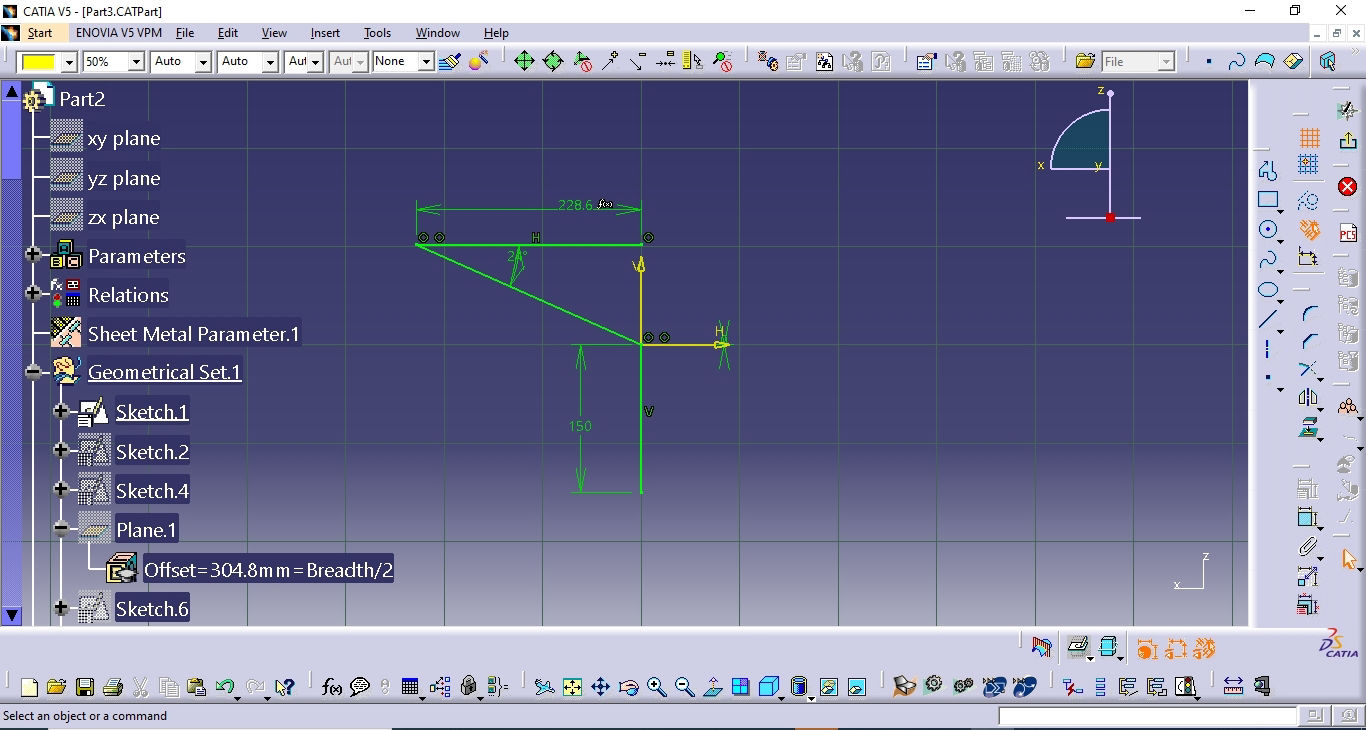
Now after applying parameters, the sketch is done and then the sketch is used to extrude to the required length. For me, it was half of the length as i will be doing symmetry to make it a full model.
After extrude, another function you often use is cut out. Is is used where you want to remove the material which will be reflected as well in the unfolded geometry at the end.
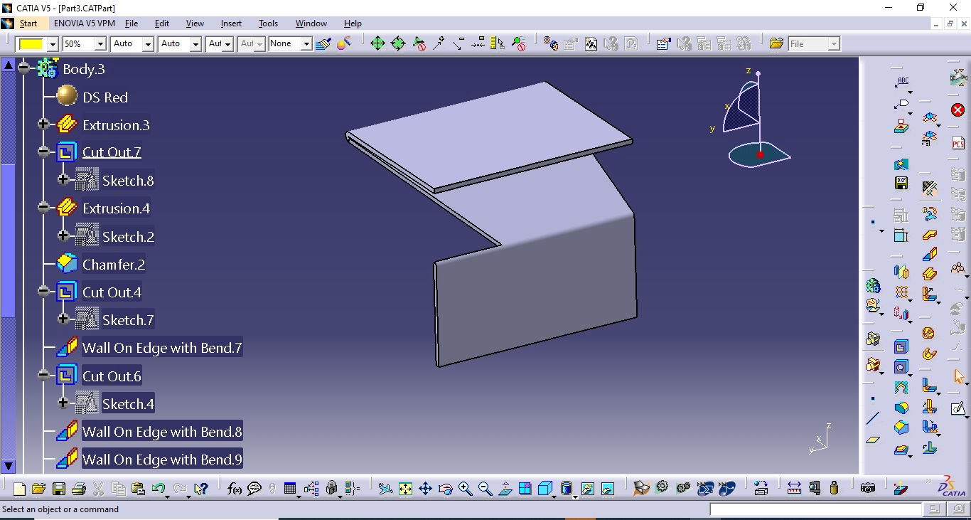
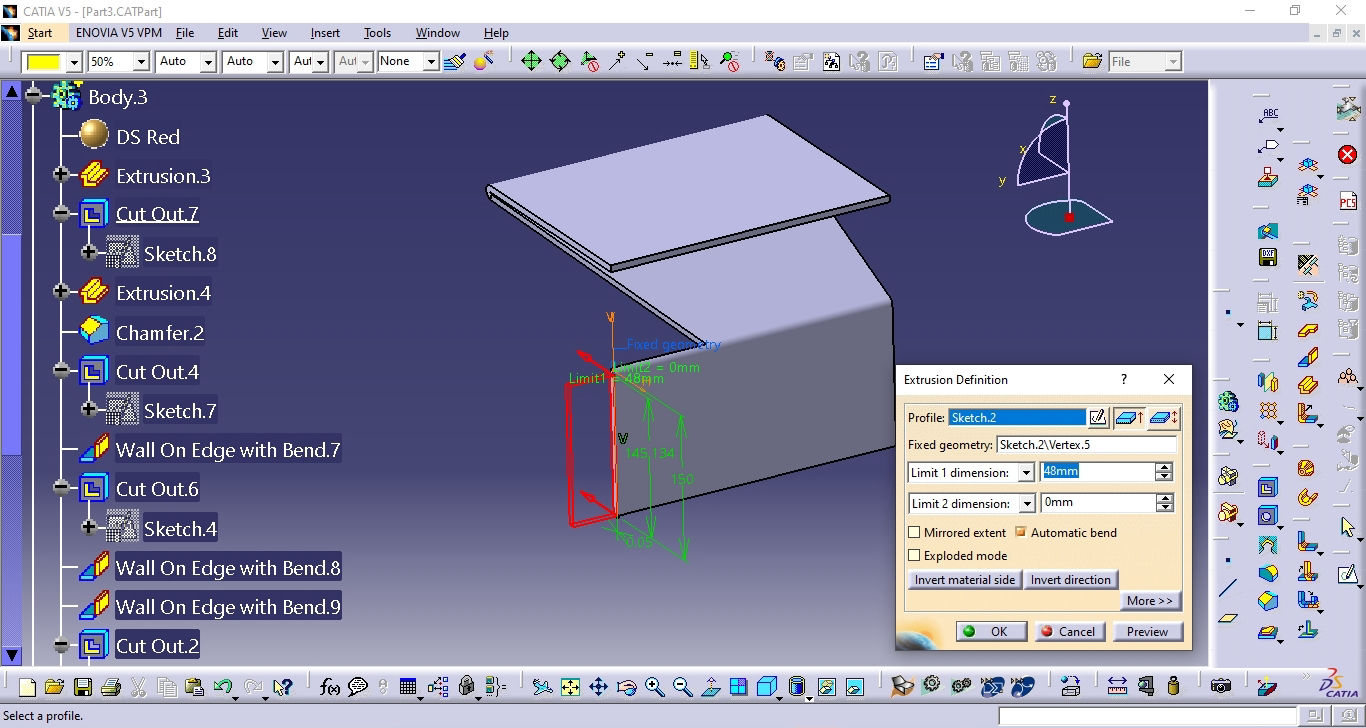
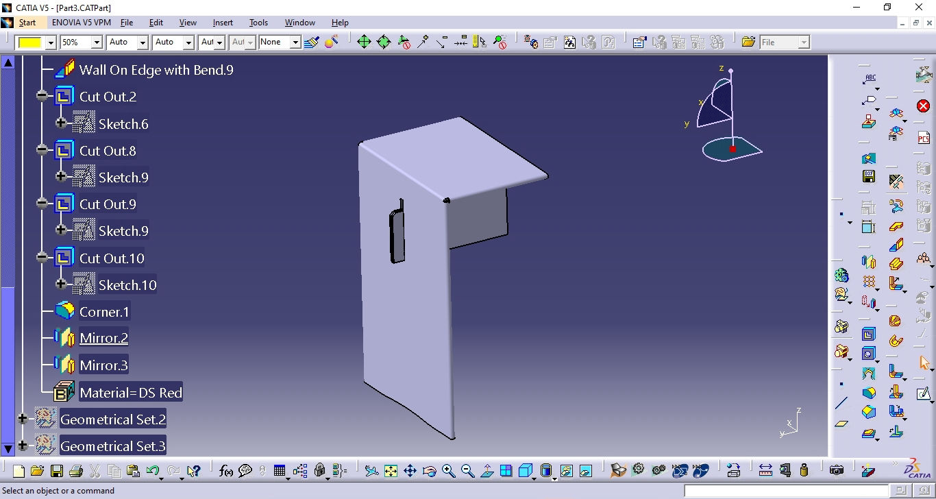
Then again I wanted to extrude some portion of it so ,I extruded from the edge that will be used as the main locking part for my design
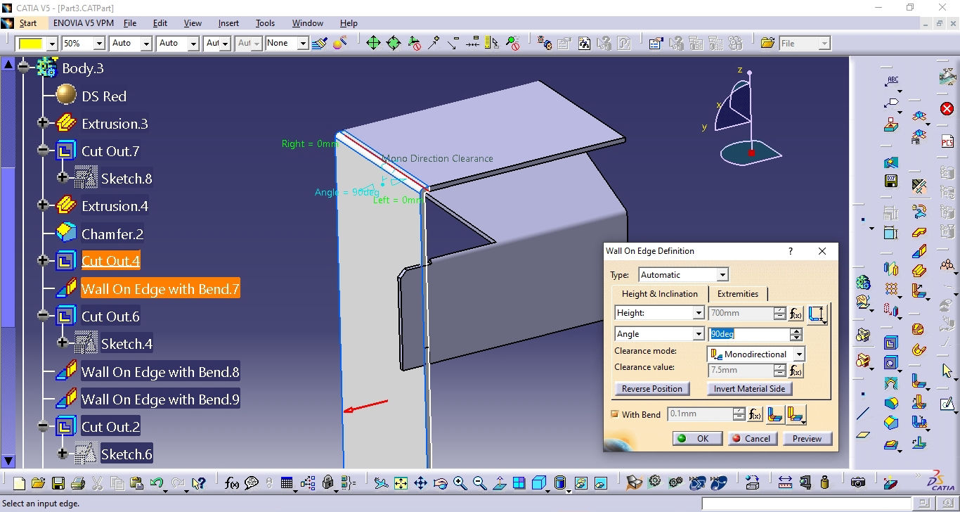
Then another important feature is wall on Edge. This tool will be used if you want to make a wall like below or bend the sheet metal to certain angle. You can choose between the angle but here I am using 90 degree as it is required as per the design.
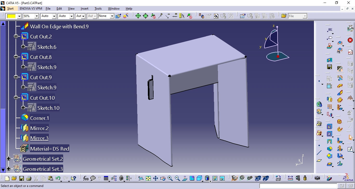
After this, Cut out is made in the overlap section with locking mechanism where the longitudinal wall underneath the table will be locked on the lateral wall of the design.
Than after the basic unit is done, symmetry is applied where the part is mirrored
After mirror is done on lateral side, again symmetry is done on the longitudinal side as well to obtain the final 3D model.
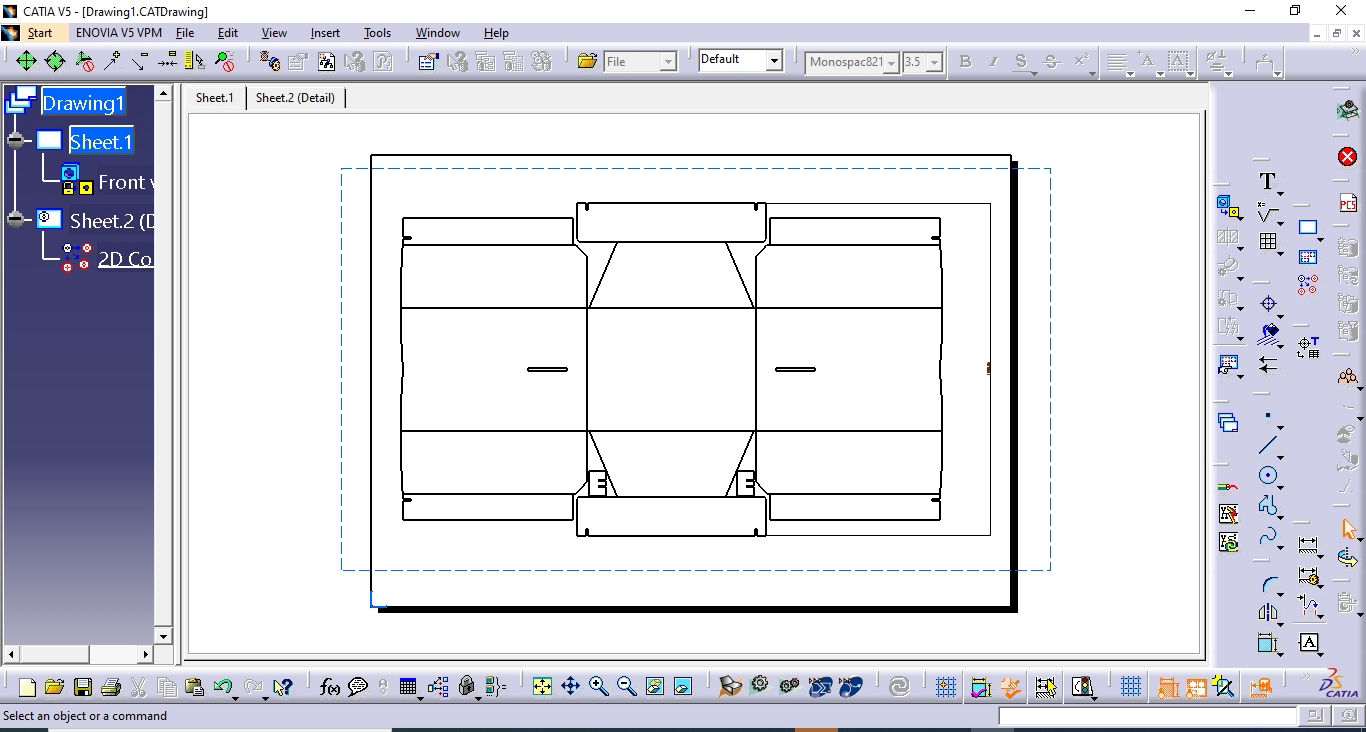
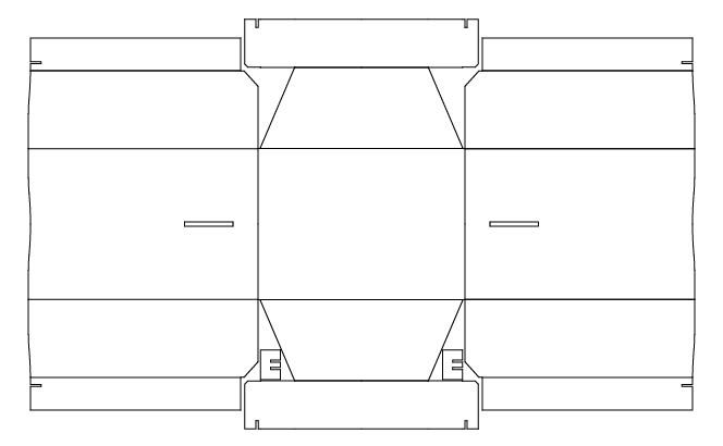
The after the 3D model is finished, you can fold or unfold the sheet so that you can see how much it occupies on the cardboard and also export dxf out for the final cut. Here the dxf dimensions will be compared as per the cardboard and the modification will be done accordingly which should fit in the available cardboard. Also while making the drawing, Take care that all the creasing line and cutting line should be present and separate from each other so that it will be easy to define the line attributes either to cut or crease or mill or anything that your machine is capable of.
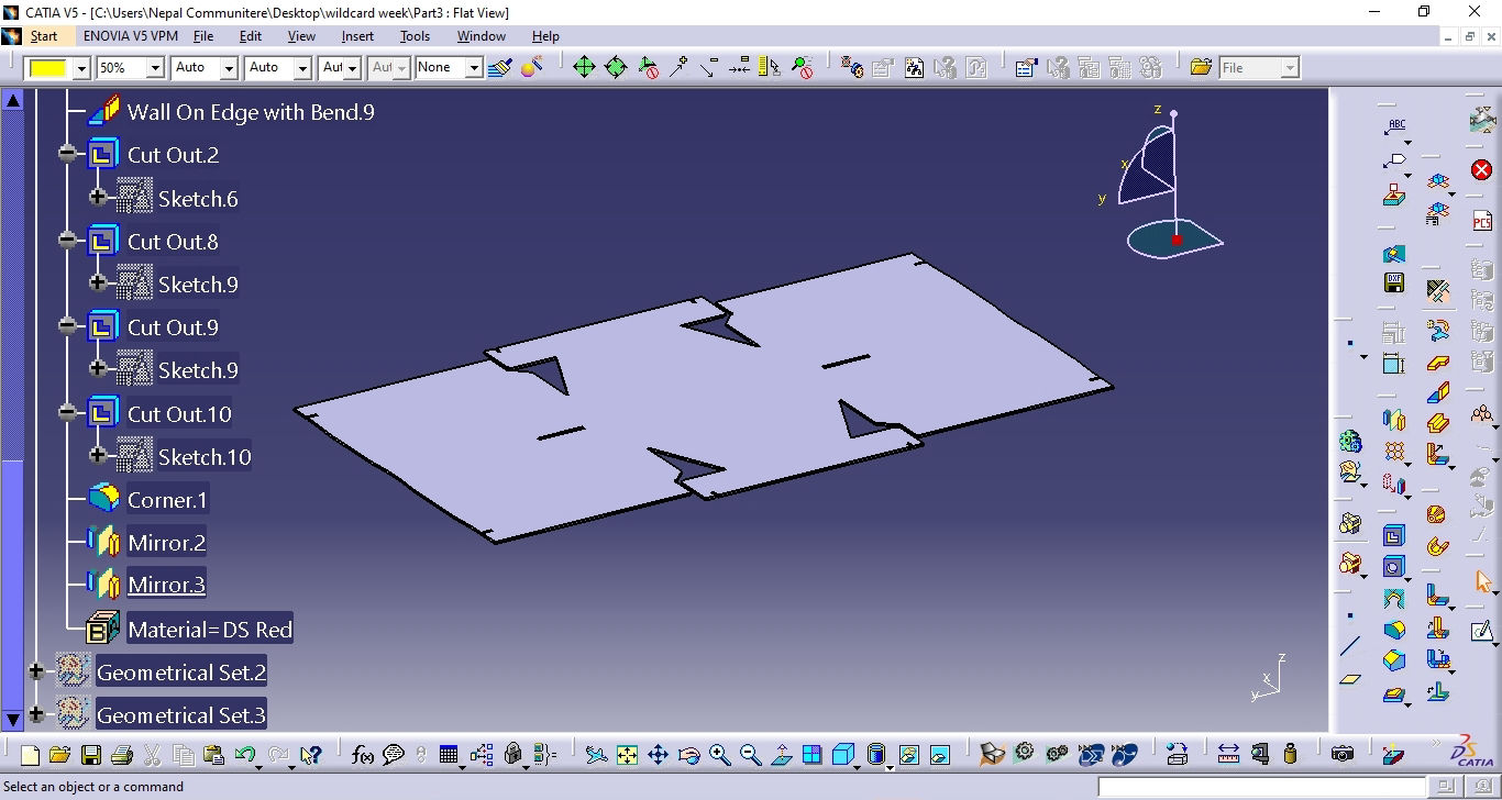
After it is unfolded, drawing is made and the DXF file is exported for fabrication
Fabrication: Software
Time for fabrication. Here after the dxf file is exported on 1:1 scale from the CAD software, It is imported in the software that zund has, i.e cut editor.
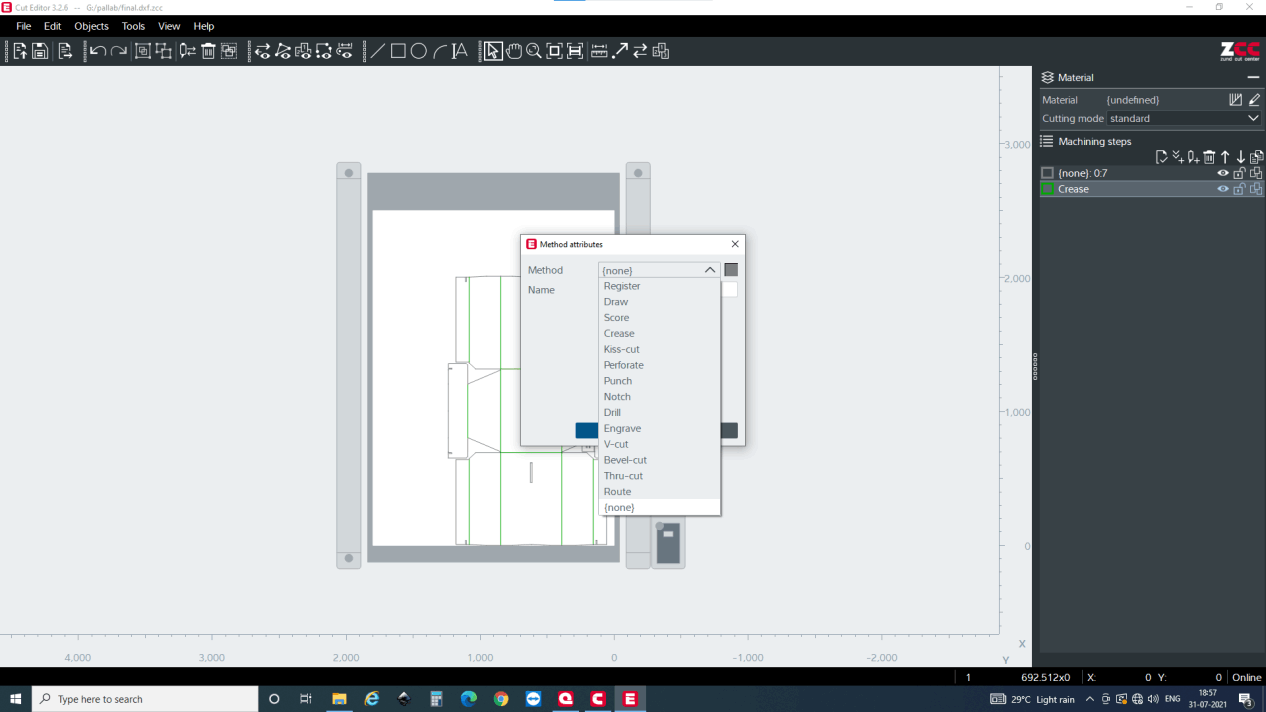
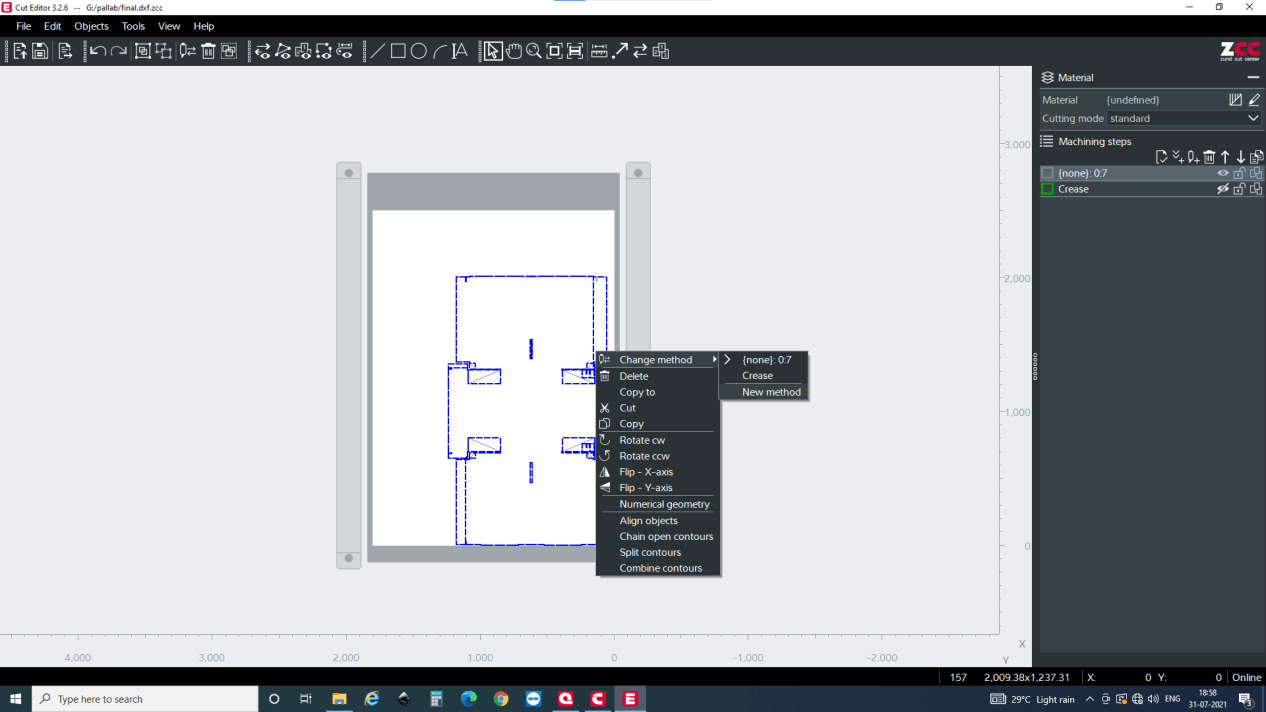
Now after you cut import the dxf file, it is great to select multiple lines and assign attribute as per you design. For me there are two main attributes for the part. i.e through cut and crease. So, first, I selected lines which is to be creased. Then after the lines are selected, you can right click , select change method >> new method and select method attributes. Here, you will have a multiple options but I need crease for now so selected crease.
One observation I had was that since it is a part body in CATIA, double lines would be there while making a drawing and then exporting it to the dxf file. Which i deleted from the cut editor itself.
You can select multiple lines and provide attributes or give attribute in groups or individually. But the lines with same attribute will be grouped together as you can see on the right part of the screen.
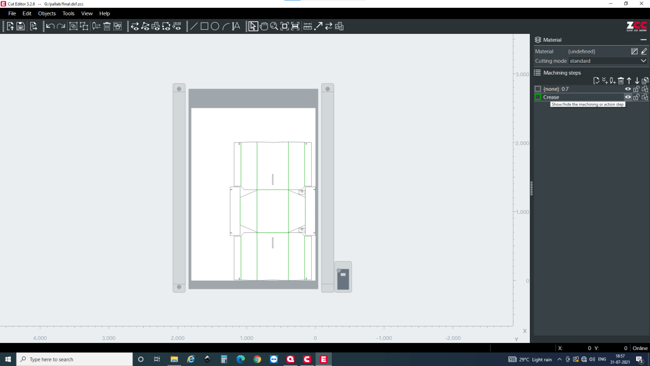
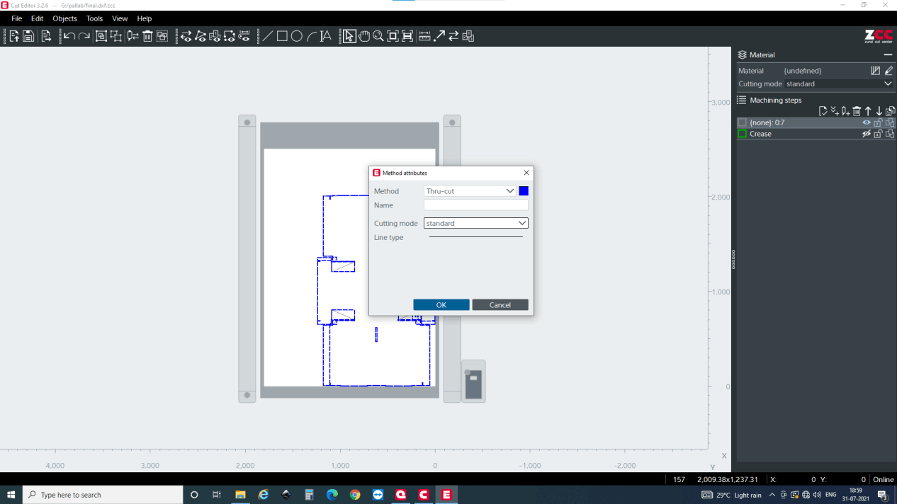
Now after all the creasing is done, i hid the creasing line and selected all the remaining lines which should be a through cut.
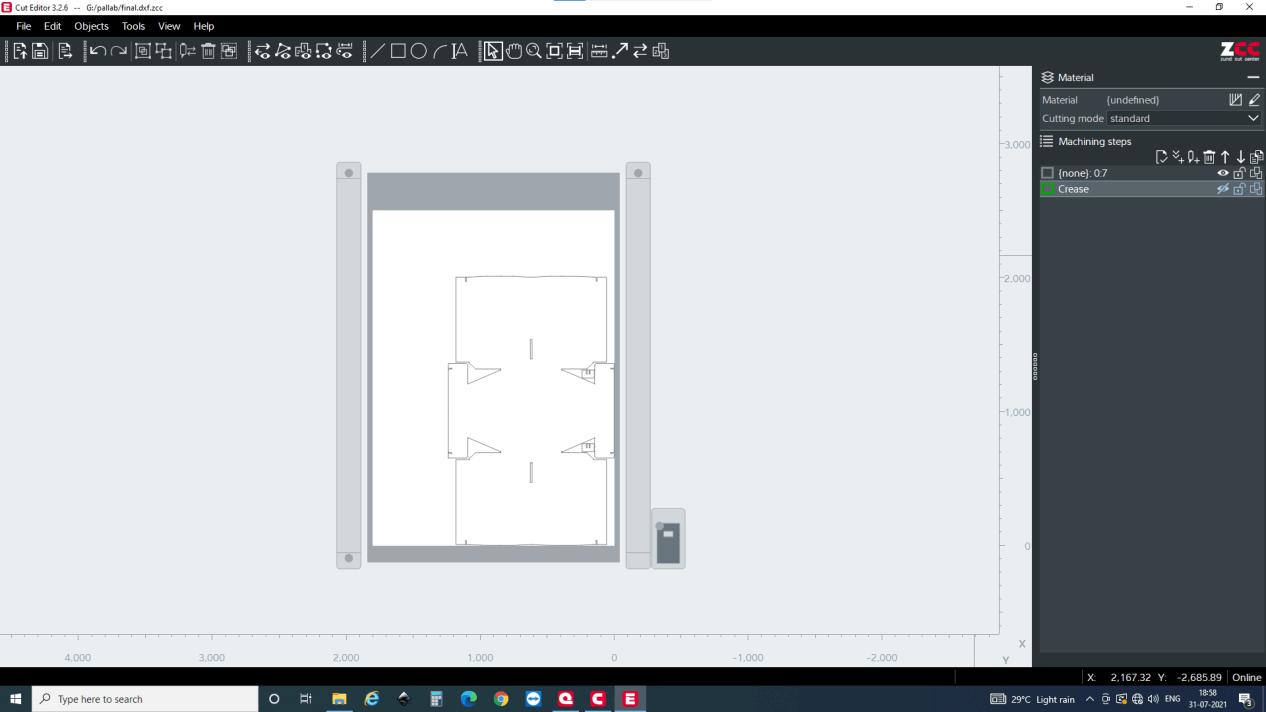
As i explained earlier, after you select all the remaining line right click, change method and and add new method and inside new method select the attribute as a standard thru-cut.
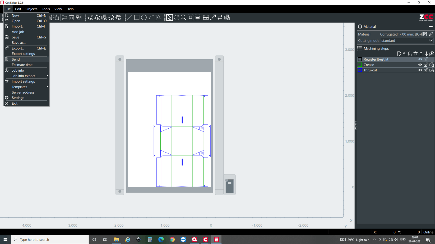
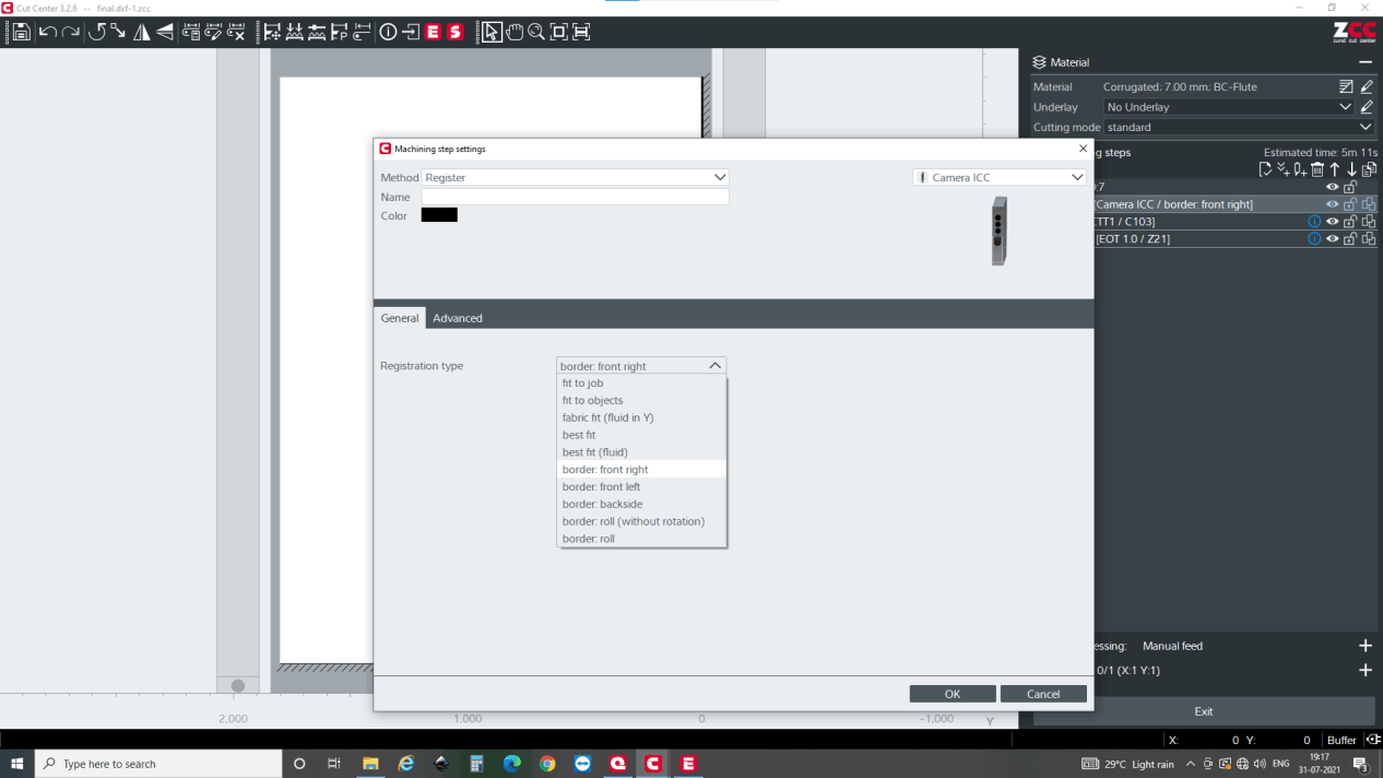
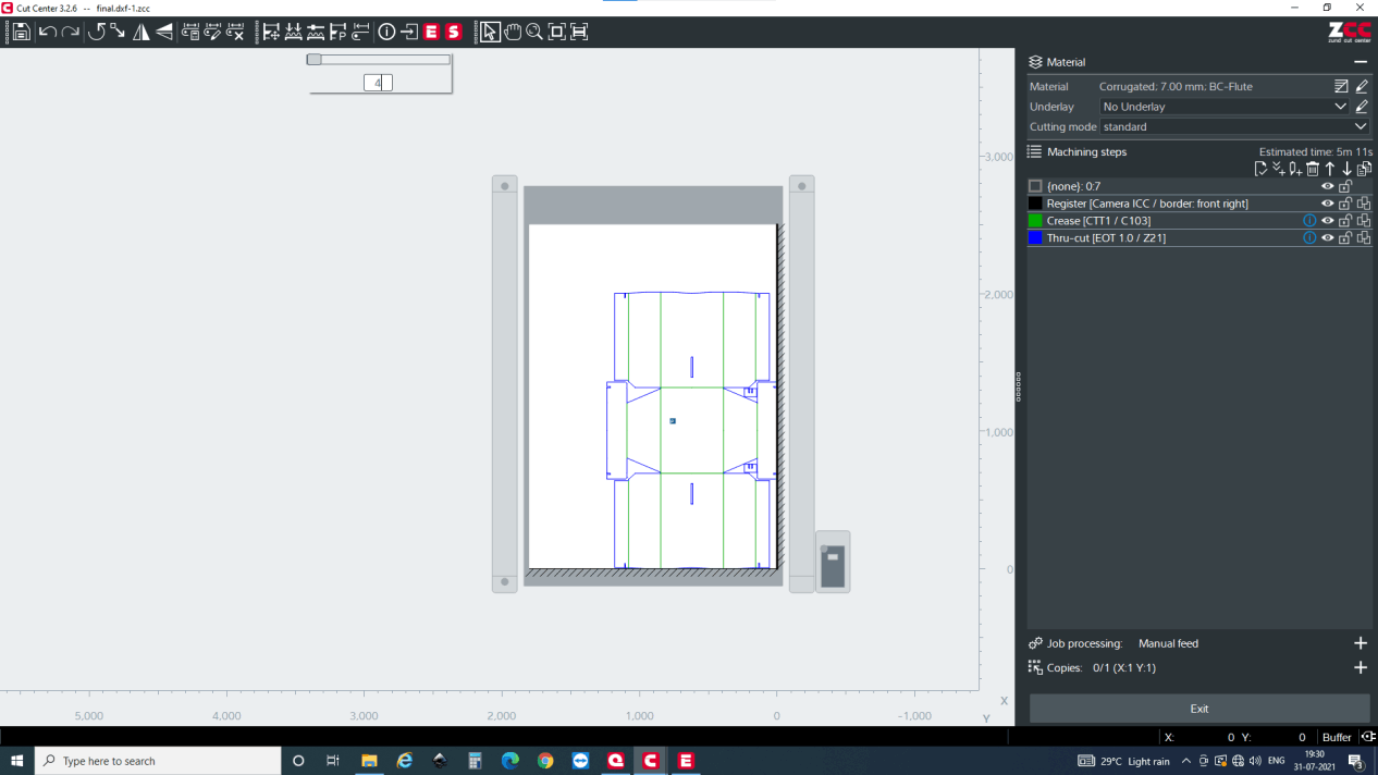
After creasing and thru-cut is added, you have to register the home position. here you have to select the option for the home positioning. I did best fit but actually it should be border front right. which I have shown you in the following images.
Now after all the attributes and camera is set, goto files and then hit the send button
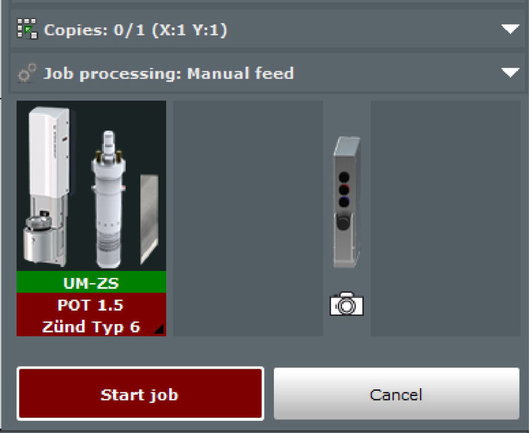
Then the software sends you to cut queue which is just a buffer app to execute the process. Double click the file you want to fabricate and it will take you to cut center and the first thing you see is it open the material selection window. For me I was using 7mm thick BC flute cardboard so selected that
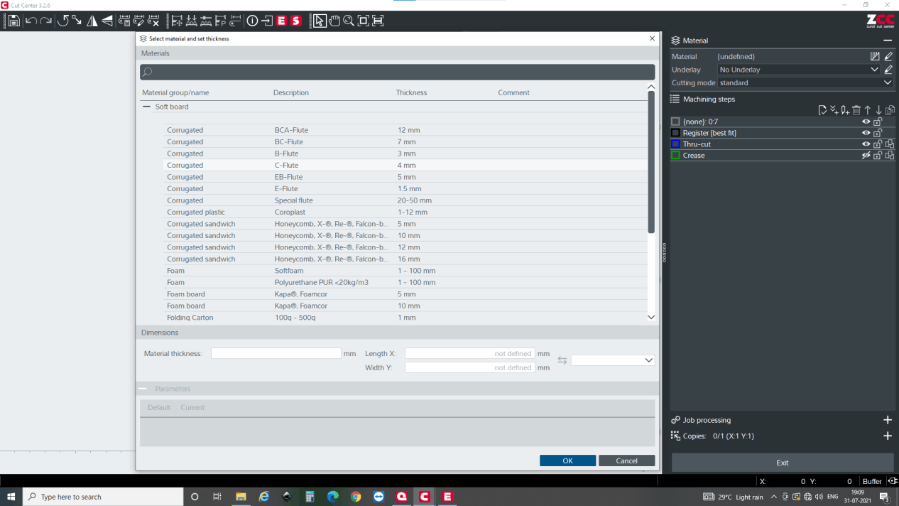
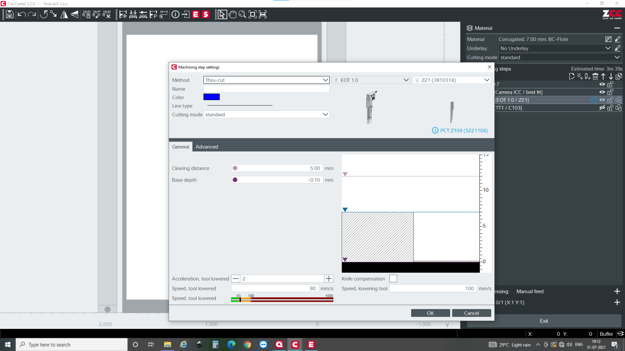
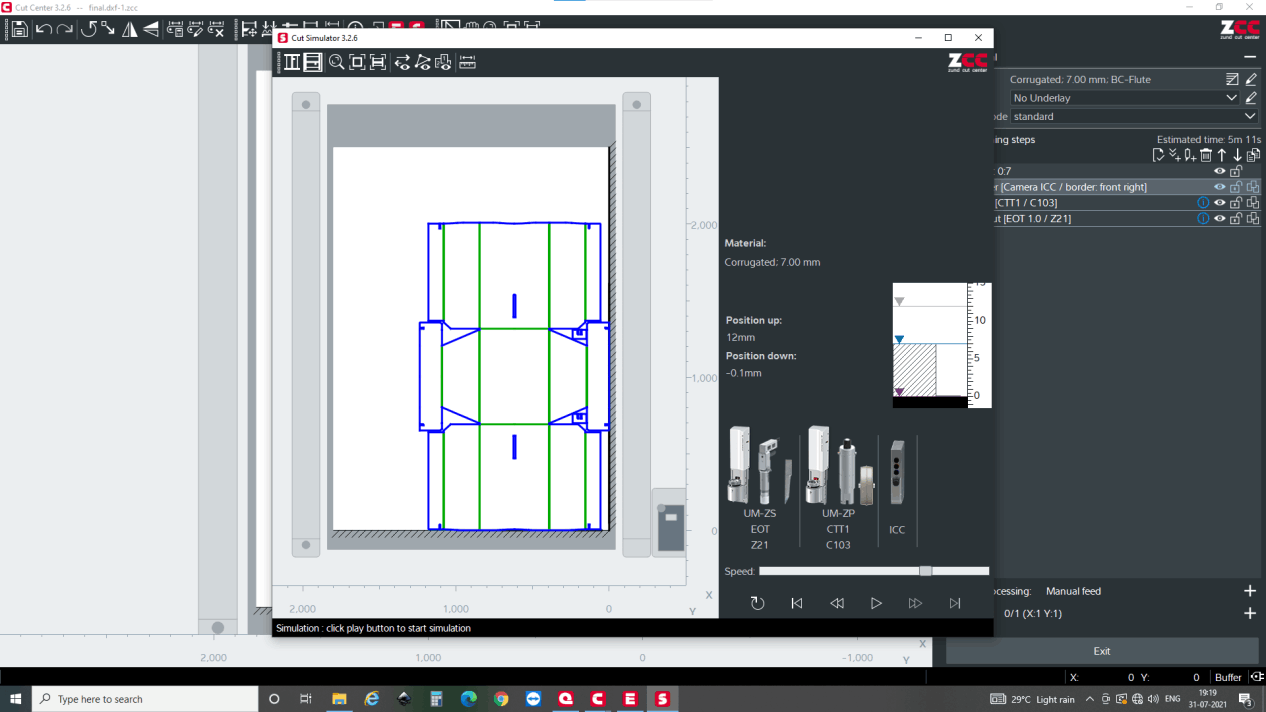
Similarly, if the material is selected, default tool is selected for the operations. Here, the Electrical Oscillating Tool (EOT) will be used ad the board is thick and drag knife cannot be used. Here software does not allow you to select drag knife which is the good thing to prevent from tool failure or ruining the material. It is set from the cut manager which I have shown in lower section. Here you must confirm that the tool must be at least 0.1 mm above the bed which you can see from the figure below.
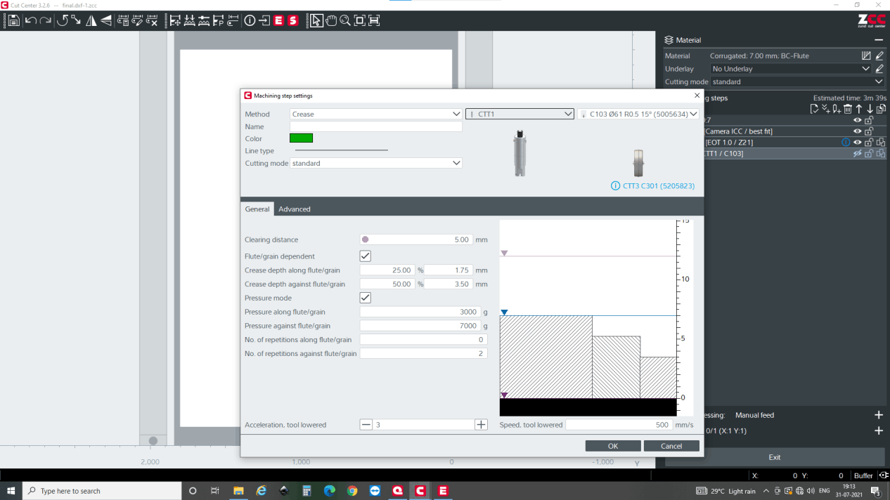
Now setting up for the creasing, first make sure creasing too; CTT has been selected. Then in the setting, the clearing distance of 5mm is kept. clearing distance is the distance of the crease wheel center from the corner. It is set up to reduce unnecessary crease.
Similarly, crease depth along flute meaning parallel to the zigzag structure is given and also crease depth against flute meaning perpendicular to the zigzag is given. Here, the depth along flute is lesser than against because, if the depth is high on along flute, it might break the outer layer of the cardboard if it falls on the down part of the flute. And if the depth against flute is less, then it might be very hard to bend the cardboard after the process is done. So currently, it is kept 25% for depth along flute and 50% for depth against the flute. You may change according to the quality of the material that you have in you facility. Similarly pressure is adjusted for both type of crease. Here it is 3000g and 7000g for along and against flute respectively.
To secure easy bending crease repetition against the flute is kept 2.
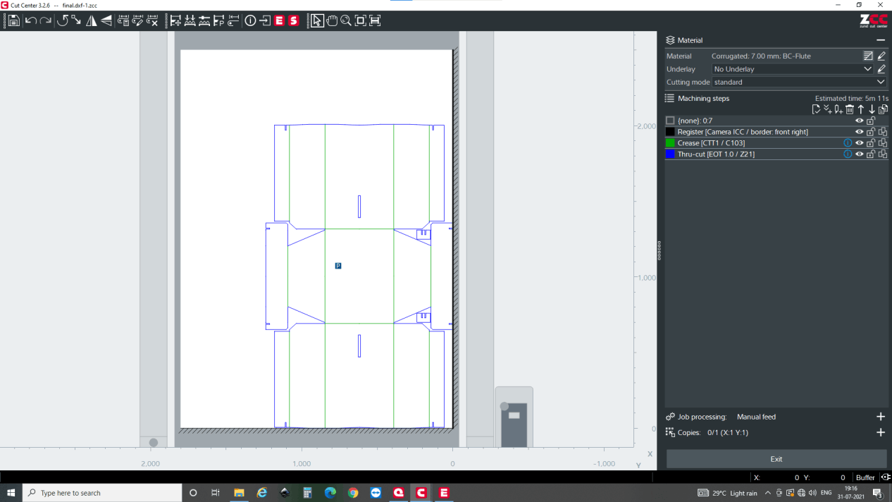
Make sure that the operation is in order meaning that first it should be register, crease and then cut.
Remember that i had mistakenly entered best fit on the section above, Here in cut editor also we can change the setting so I changed it to border front right. which would be easy to set.
Now vacuum pressure is set for your material. Please use the flat material without bulge. If there is a bulge air cannot be completely pulled out and the vacuum clamp do not work. So, either use the flat material or make it flat before use. Now the vacuum pressure is set according to the clamping force. Put the vacuum 4 for now and try to move the material. If it is not easy to move, It is ok but if it moves easily, increase the vacuum pressure
Then, after everything is done you can simulate it and aircut it as well. First of all, do the screen simulation. Click on the screen simulation as shown in the figure below.
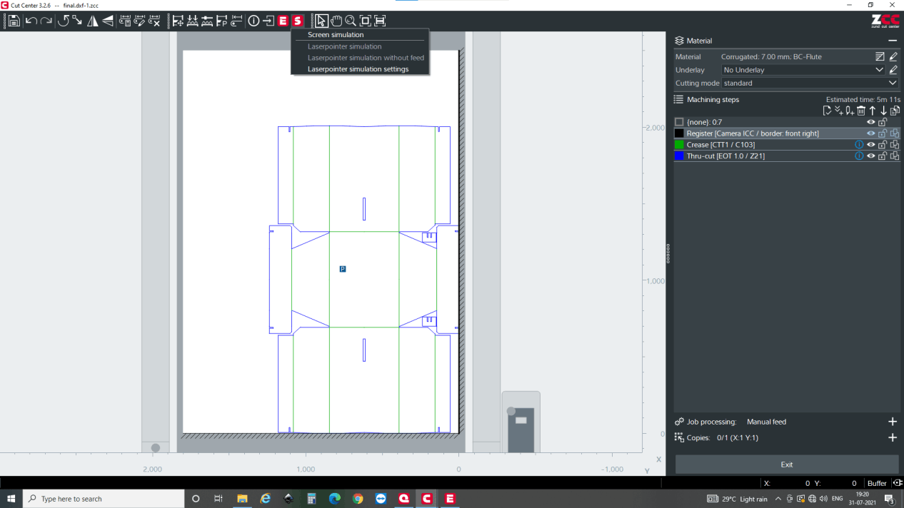
The cutting and creasing will be shown in the simulation on the screen. While simulting, it also shows you the tools that are being used in different steps. After it, you can aircut it as well. For it press laser pointer simulation.
After you press laser pointer simulation first you have to register the home position where you have to move the camera to the edge from the right/left and top/bottom arrow kwy in the main control panel of zund. then the machine will automatically trackdown the rest. After it is registered, it starts air cutting where you can confirm if your design fits on the board size that you have choose.
For me, it was 10 mm bigger, so a scaling down was done by size keeping aspect ratio same. This was insignificant for the cuts and holes because the change was 0.035 mm on the cut. and after it was rescaled, aircut was done again which assured that the design will fit in the material. After that, the process is started.
Here the speeds are as follows
1. Creasing: 600mm/s
2. Thru-cut: 80mm/s
3. Jog speed: 1000m/s
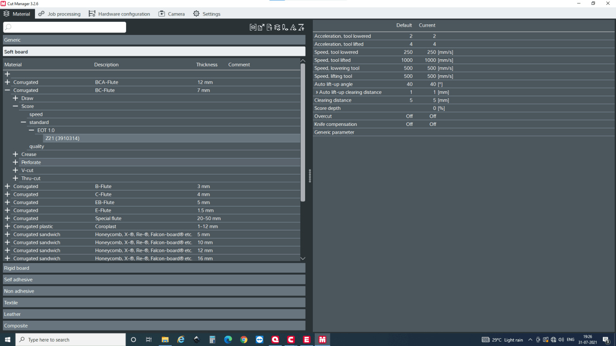
For the main operator the operations mentioned above is enough. But to set up the tools and the setting for tools, you can edit it via Cut manager. This application allows you to set different tools for different types of material and different thickness as well. Here default value is given and you can use default value or tune it according the material found in you local area. For setting a new material, you can also send the material to ZUND and they will test and send you the setting details for free. However if you want to set yourself try from safest position with less depth of cut and less pressure and then depending upon the test piece, set it.
For most of the people, first hing would be changing the unit and language setting, Hence it can be set by going into setting and general in which you can set up the units and language
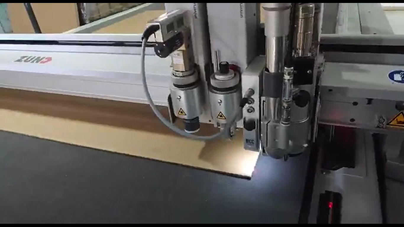
Fabrication: Cutting.
Then on the machine side, first check that you have the right tool on both creasing (CTT) and oscillating tool (EOT) on the module secured, if not set it.
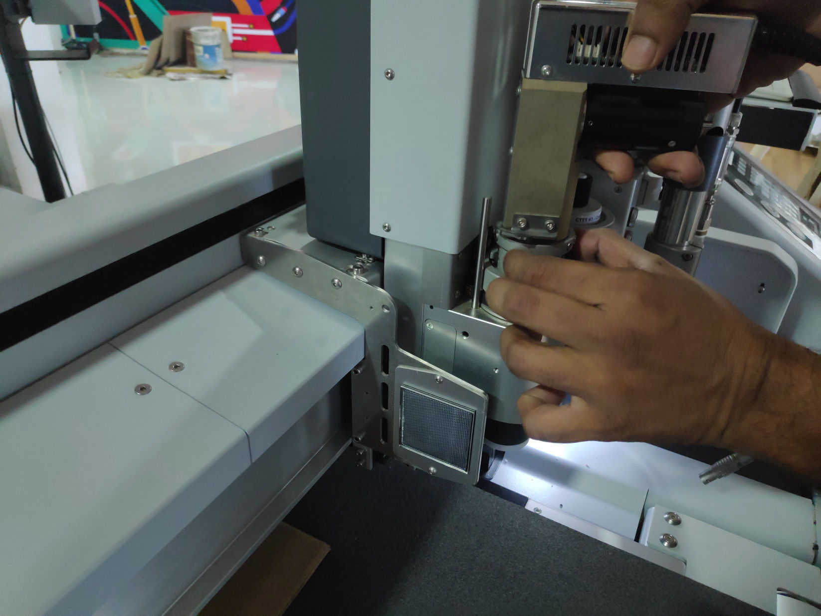
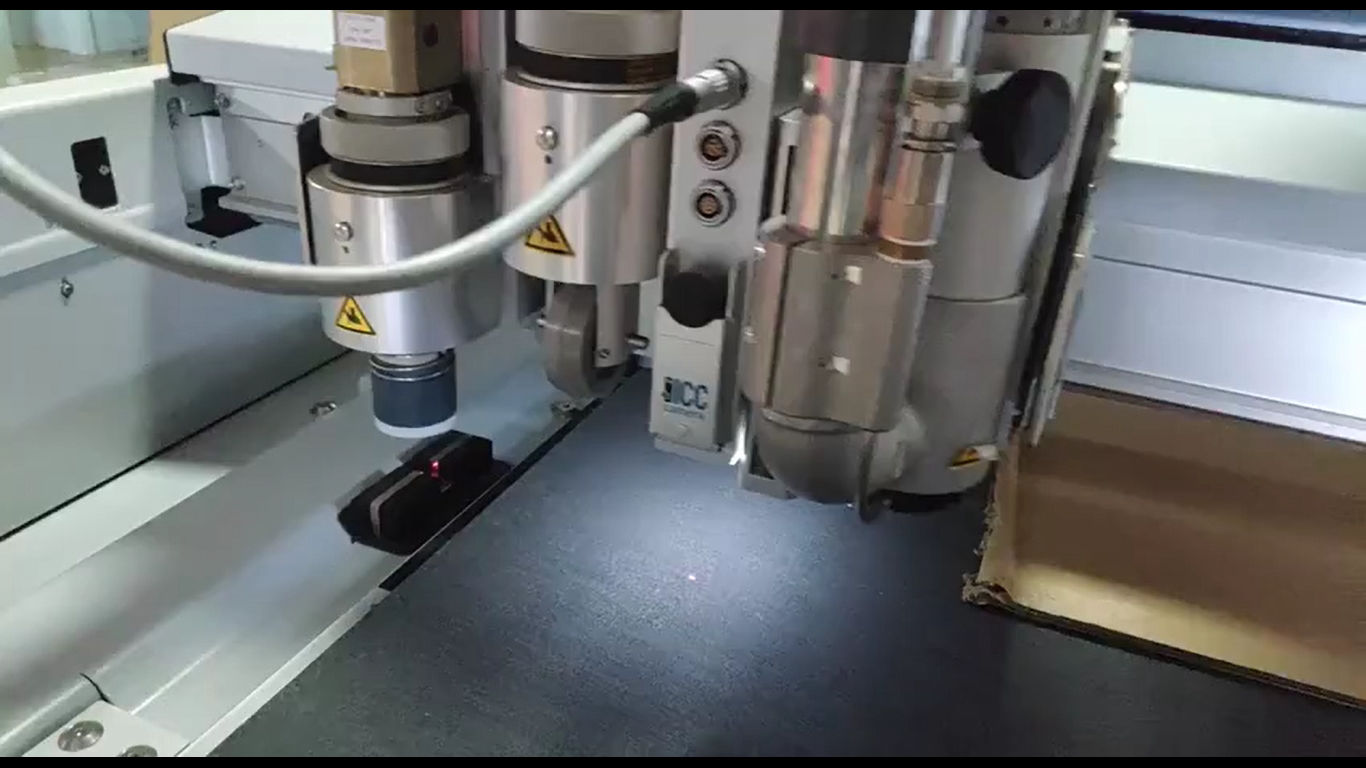
Then you again have to register the home position for X and Y axis. Then it automatically sets up the Z position by different process. For creasing, the creasing wheel is pushed against the datum and force is taken as a reference to set up Z height. How ever for the oscillating tool, the tool is reciprocated in the above laser until it crosses the laser detecting the Z-0 height.Please click the image for the video
Air cut is done for the confirmation
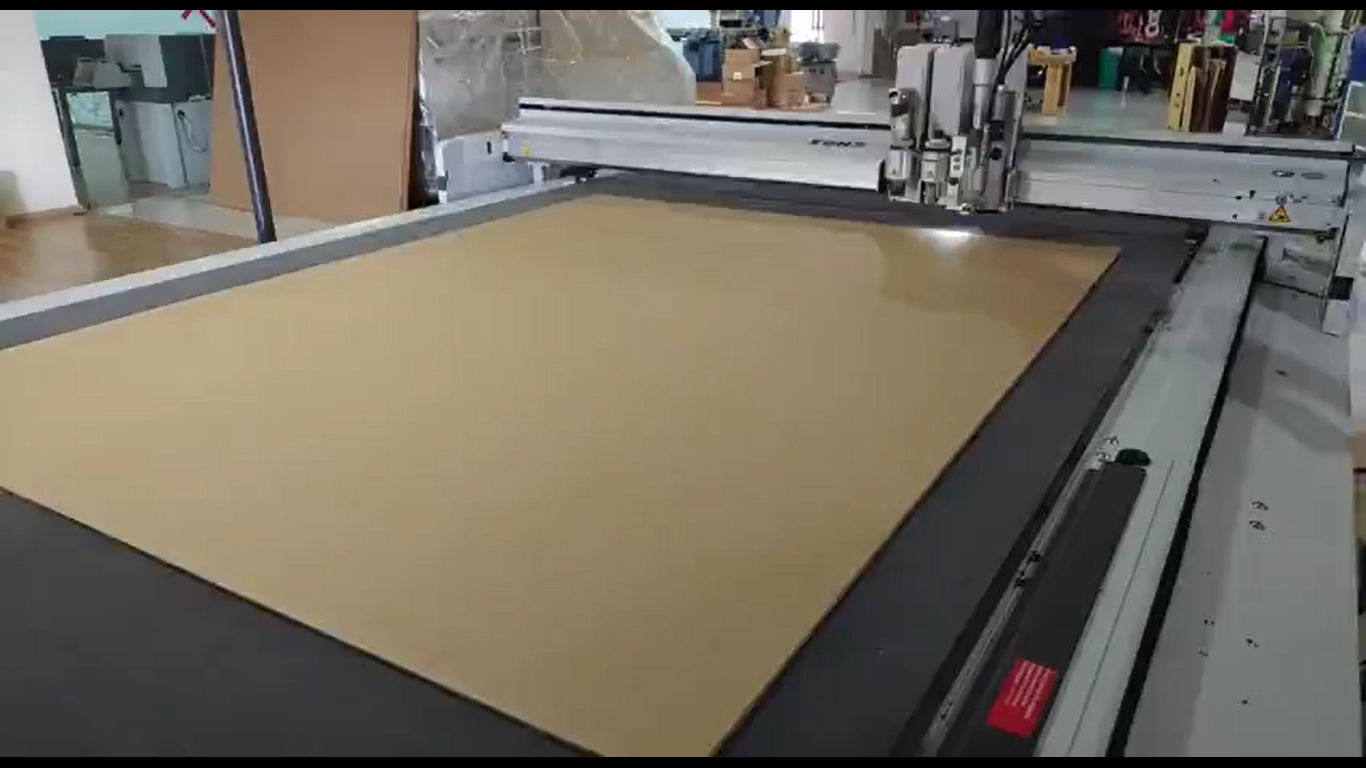
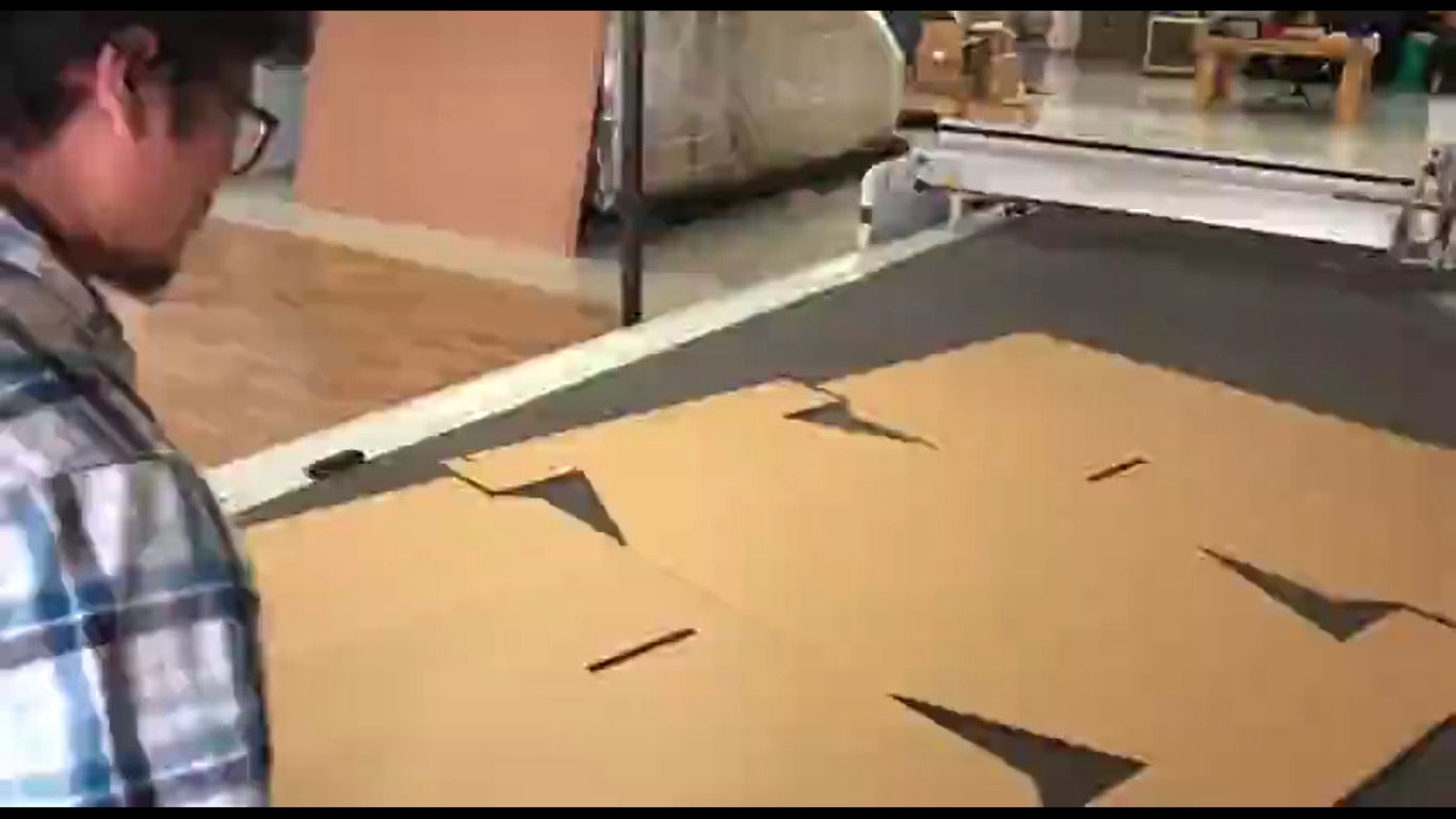
After everything is set up, process is started
Finally folding it together
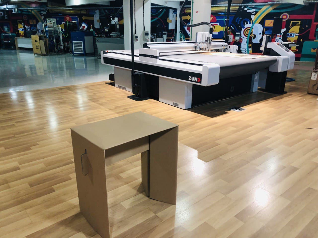
Usability
As table can be assembled on site easily, it should very easy to move it unfolded. It can be transported to remote areas or lots of tables can be transported in a small vehicle which will reduce transportation cost and large number can be transported in once, Hence, can be used in schools and places where it is required immediately as well.
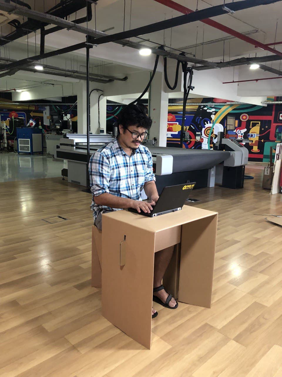
In addition it is a lightweight and also costs less so can be more economic for using it in a dryplace. However durability may be lesser in compare to wood. Laminated cardboard can be used for long life as well.
Hero shot of me using the table.
Web page was designed with Mobirise