Group
1. Design a machine that includes mechanism+actuation+automation
2. Build the mechanical parts and operate it manually
3. Document the group project and your individual contribution
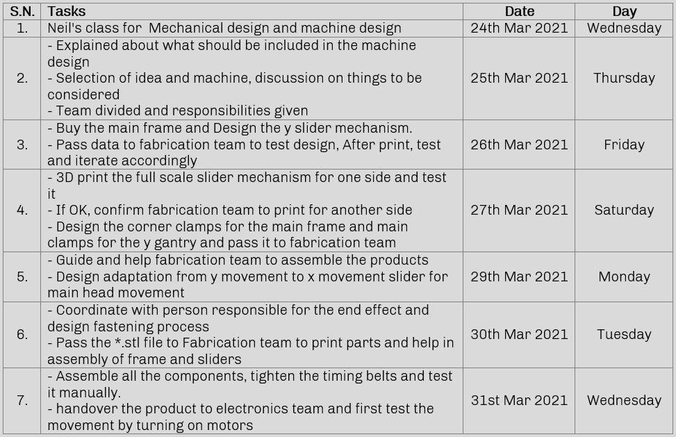
Plan for the week

This week is the week where we use our core skills and do team work to make a machine. We brainstormed several ideas for the group project which included: Selective White Board Eraser, Waste Picking Robot, Table Cleaner, Juicer etc. and fe had a good and healthy discussion around what project to do to learn most from the assignment as well as from team members and also finish it on time. Good that we had started this discussion early before the assignment week. Then we divided ourselves according to our strength and agreed on sharing what we learned as we move on which will make effecient use of time. Here is a picture showing our brainstorming session with the help from our instructors.
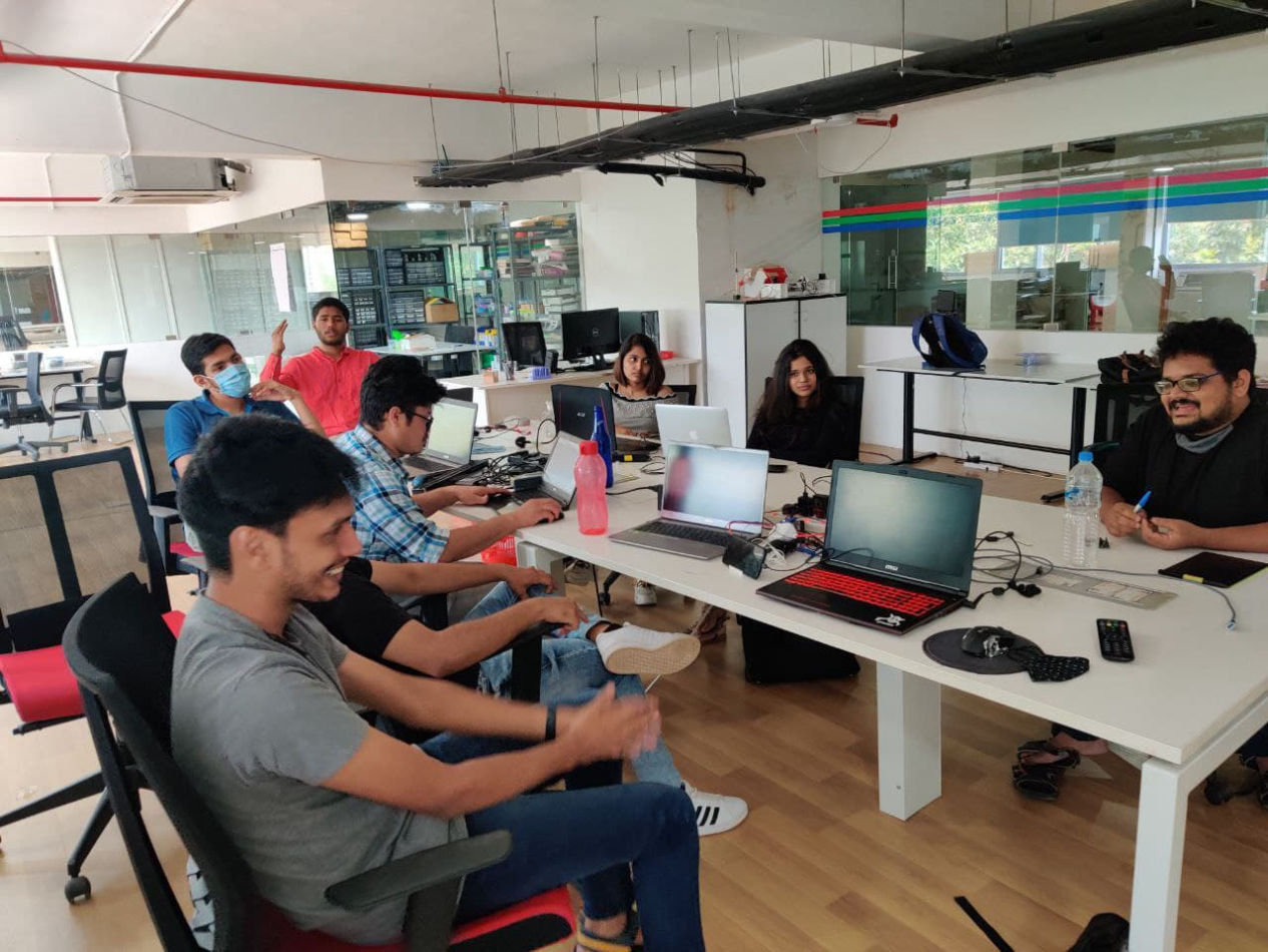
(PC: Abhinav Ajith)
Though we had many discussions around assignment, and as recommended by instructors, we selected CNC
plotter as our main machine to be designed We selected core xy as the main mechanism. The main reason to select this mechanism was we focused more on learning more than inventing something new. Our machine will designed considering following factors.
1.Functionality.
2.Time for fabrication.
3.Design for cost.
4.Availability of parts.
Talking about Core XY, First of all Thank you to Ilan E. Moyer for the great documentation from which we could learn a lot. Please refer to this documentation for the detail theory
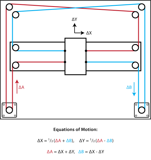
Motions:
1. Horizontal when the motors rotate in the same direction equally
2. Vertical when the motors rotate in opposite directions equally
3. Diagonal when only one motor rotates.
Then we divided the team into five groups:
1. Mechanical Design (I am in this group)
2. Fabrication
3. Electronics and programming
4. Material and management
5. Documentation
We Went through various process from designing, fabricating, testing, assembly, and most importantly prototyping a lot of mini parts as per designs.
As a team we first discussed will all about how to make it. For the driving system, timing belts with stepper motor was confirmed. Then about the movement we were discussing what to use for the movement were we were searching for the options like
1. Laser cut frames
2. Steel rods sliders
3. Linear rails
4. Metal sections
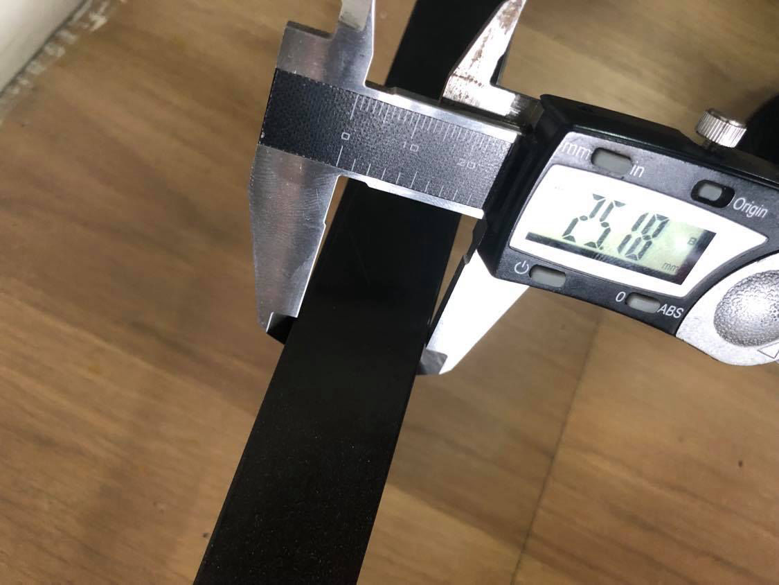
When we were discussing our instructor Jogin Francis asked why don't you use aluminium extrusion. Then we tried searching for those in the lab but could not find one. Design team with material team went to search for the aluminium extrusion section of size 25mm X 50mm. We confirmed that there was not irregularity over the length and its strength. The reason we chose aluminium extrusion is that it was cheaper and it was locally available, since it was made by extrusions the section would have a dimensional consistency throughout its length and another point to note is that aluminum is a soft metal so common cutting and drilling tools can be used in the material. However, we should take care of it while handling during assembly and machining as concentrated force may damage the surface or whole shape. But it was lightweight and OK for our group project.
Along with the help of fabrication team, we figured out the calculated space for stepper motor and cut the parts into 5 pieces 4 for sides and one for x-gantry.
For that we got out specification of our machine size wise
Machine size: 1110mm(x) * 1060mm(y) * 175mm(z)
Bed size: 766mm(x) * 756mm(y) (Updated after designing)
Now we all divided our works and done our part and then met at assembly. Where all the parts assembled and mechanically tested. and boards were installed and then tested.
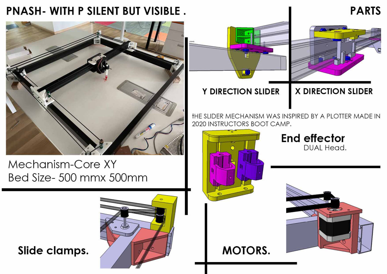
Designs
Please follow this link for the group website.
Individual Contribution
First thing to do was take exact measurements of the extrusion and then make a parametric extrusion which I can copy for the different sides and gantry.
Slider design
We had 2 options to choose between
a.Linear rails
b.Make our own sliders
we decided to make our own sliders because linear sliders were expensive and it was unavailable in our lab for the length that we targeted and what we had was shorter ones. So moving on with designing slider first y direction slider was focused. I then followed the following process.
1. Bearing dimension were measured
2. Total of 6 bearings,
a. 3 will be placed vertically constraining z motion and rotation about x direction
b. 3 will be placed horizontally constraining x movement and rotation about z direction which leaves the y direction
movement free as rotaion about y direction will be contrained by the gantry on the other side.
3. As fabrication team was testing the inserts to be used, The gap for inserting the inserts for the hot rod as well.
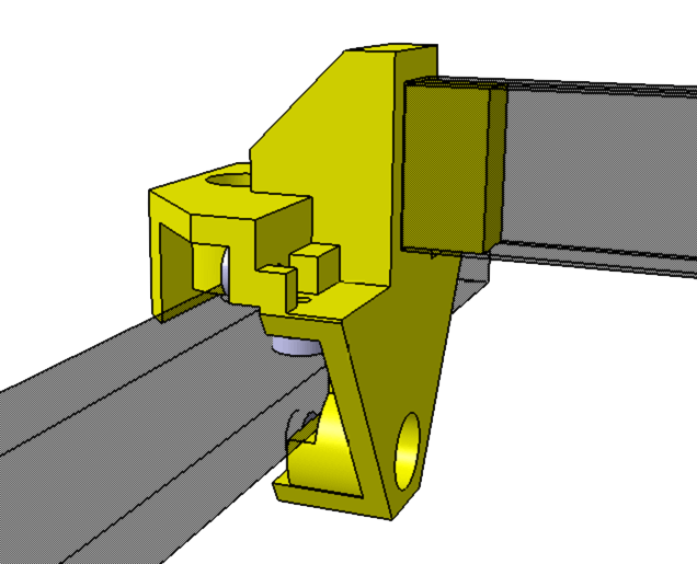
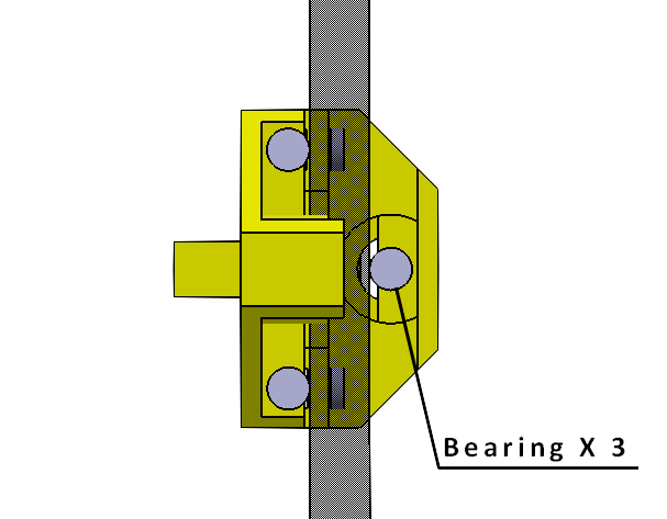
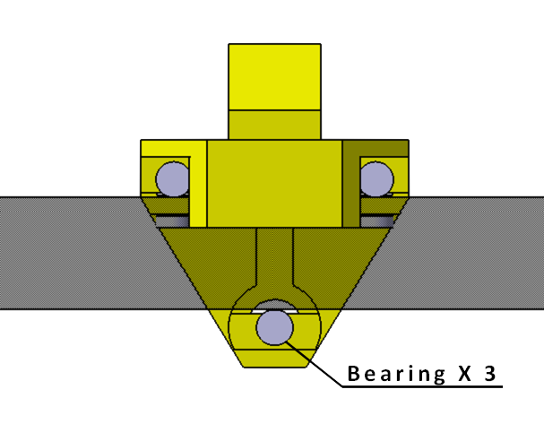
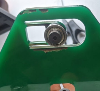
The main problem for this slider was that while assembly was that the extrusion and the bearing should fit perfectly. IF loose it would giggle and if tight, it would need a lot of force to drive it and while i was thinking about ways to add flextures in it, our instructor Jogin Francis suggested to refer the slider that was used in Instructors bootcamp 2020 in Fablab Kochi. It was great design and so impressed with the simple yet effective design.
Then I tried to take a reference of that design and work on ours. While doing so, first thing to do was make couple of prototypes for flextures
Flexture for sliders:
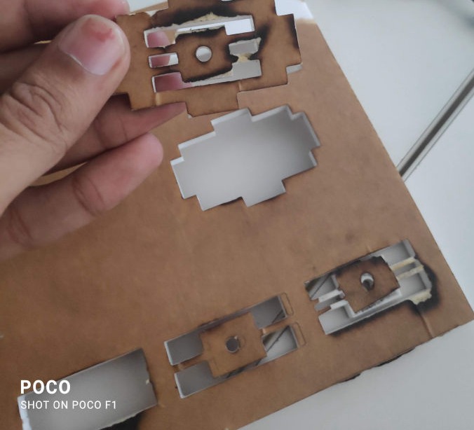
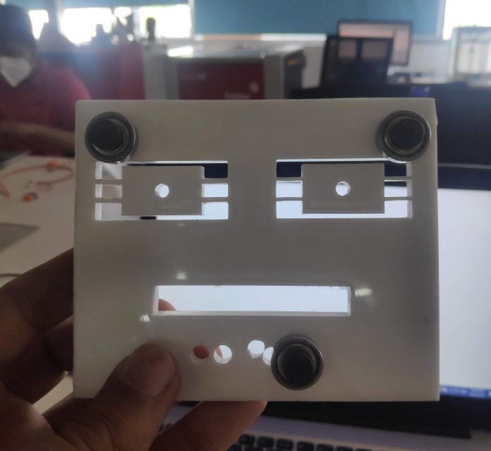
For making the slider first thing to consider was the possibility of surface irregularity and the tolerance of the part that we are about to create. So a flexture component has to be made or there would be a wiggle while movement or if not, it would be very tight assembly. We made a flexture which can flex but also can limit the displacement as it is applied, other forces should not break.
version 1: with connector on both sides
version 2: with connector on only one side
We tried different materials and we found which is accurate for our machine.
1. we tested in acrylic which is cut out using laser cutter.
2. we used PLA (Poly lactic acid) which was 3D Printed from Ultimaker.
we found that using PLA was more accurate for our design because while we tried acrylic it tend break because it was more brittle compared to PLA. The acrylic part broke while we were assembling it with the aluminium extrusion
Then following samples were made
Learnings:
1. Acrylic are brittle and are relatively harder to flex than 3D printed parts.
2. If you have flextures with two arms it is hard to flex as when one arm is compressed one is in tension and becomes similar to having wide arm with compared to flex but stress concentrated highly on the join where is connected to main body. However you can use it according to your design requirement.
3. It is better to have limit for the movement as if moved a lot , it might break the flexure.
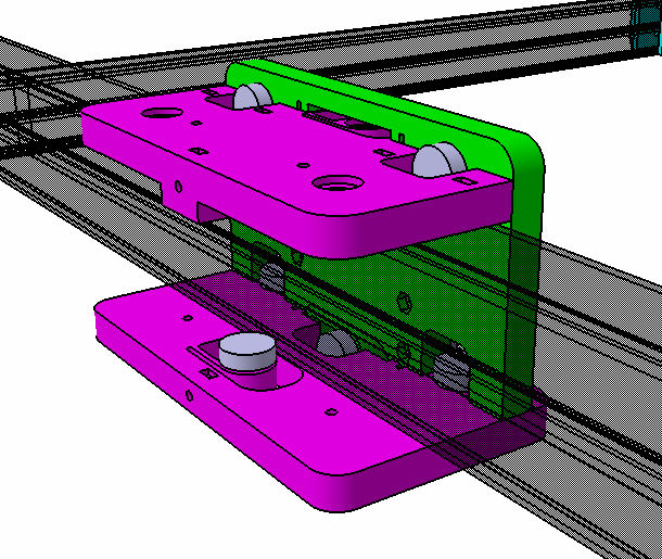
After the flextures were finalized, 2 plate design was made where the central bearing of horizontal plate would go through the vertical plate and both will be assembled by m3 nuts. in 4 places.
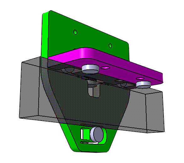
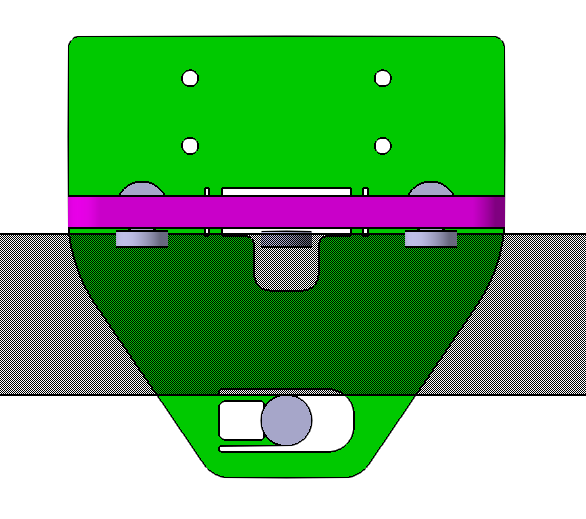
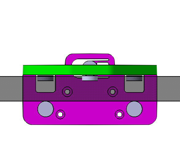
Similarly, the extrusion for the x-gantry should be included into design as this part was also holding it. then I thought that will clamp it via two brackets with the extrusion sandwiched in middle.
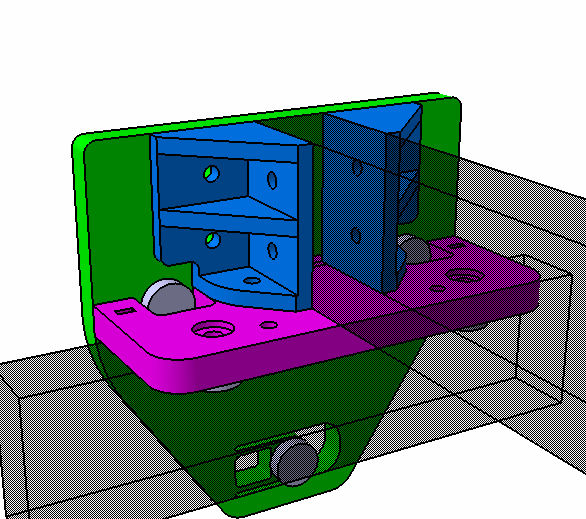
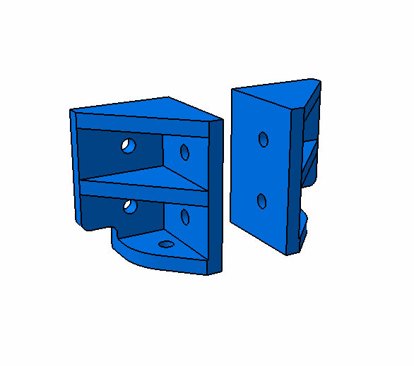
Then the design files were sent to the fabrication team and first it was tested.
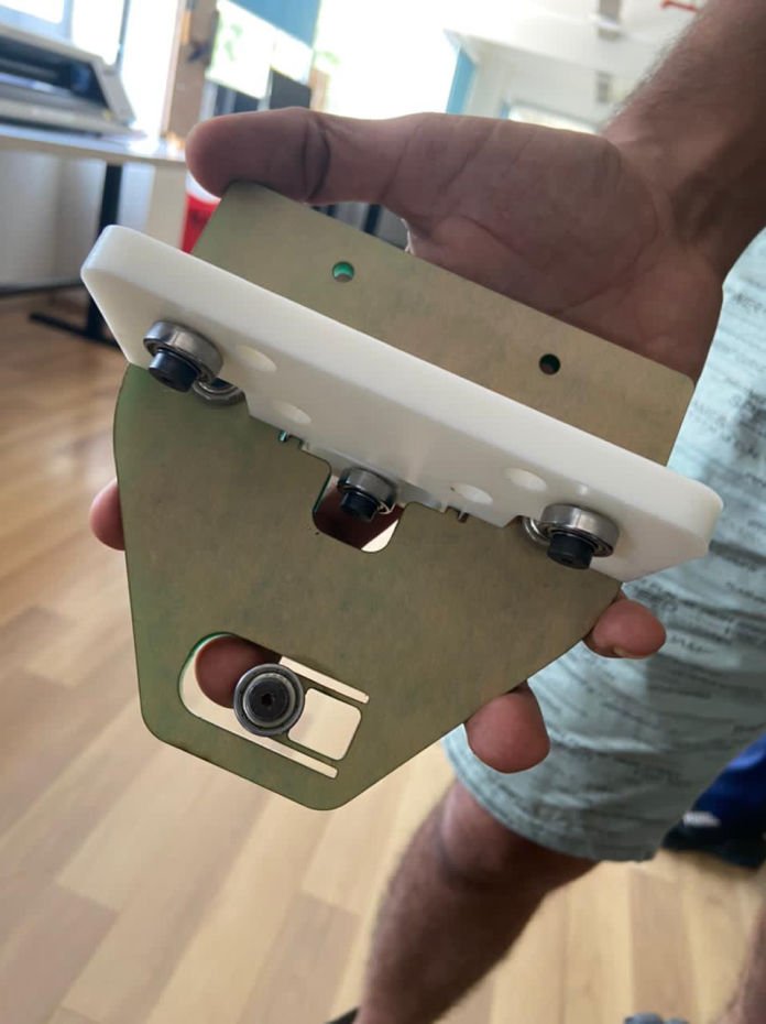
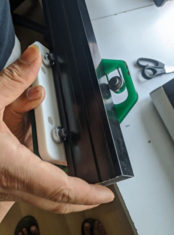
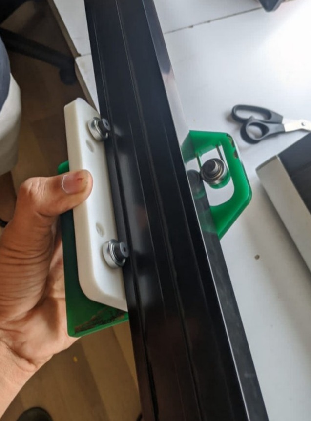
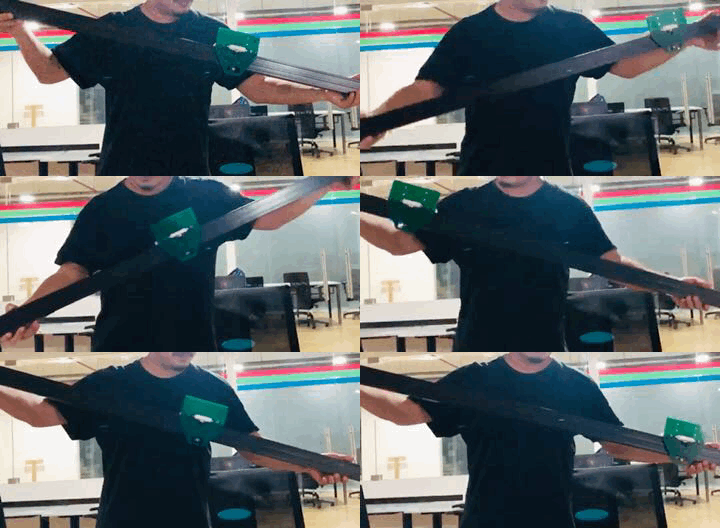
While the testing was going on, the bracket for clamping in each corners had to be made, housing for motors and along with that, brackets two brackets on the opposite ends had to be designed so as to hold pulleys for timing belts.
1. Bracket for corners: It is a 90 degree bracket which will be fitted by M5 nuts and bolts. total 4 and 2 on each sides.
2. Bracket housing motors: 4 servo motor screws on the top and 4 with two on each side aligning the corner bracket. Both are of different heights due to different levels of the timing belts.
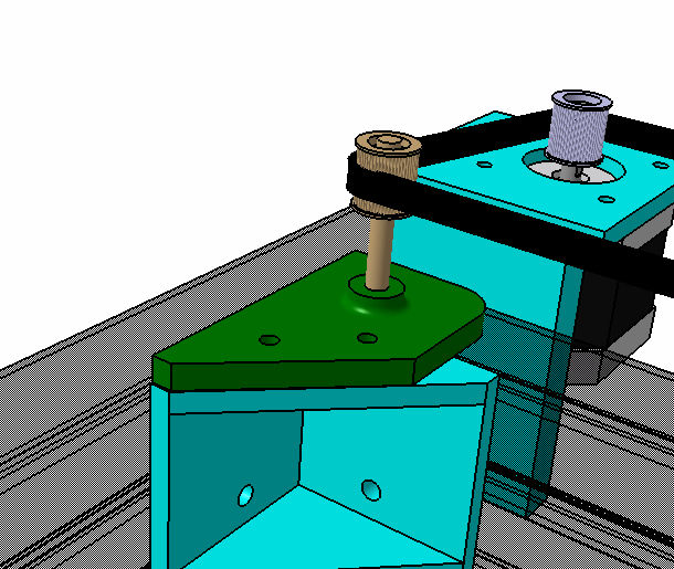
3. Bracket for holding two pulleys of timing belt: Both are complementing stepper motor and placed opposite to it. Each one can fit two pulleys with washers and be clamped to the main frame. Long M5 bolt is taken as shaft inserted from below. It is clampedto the main frame by two M5 bolts and nuts
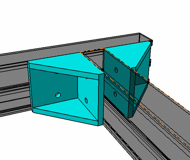
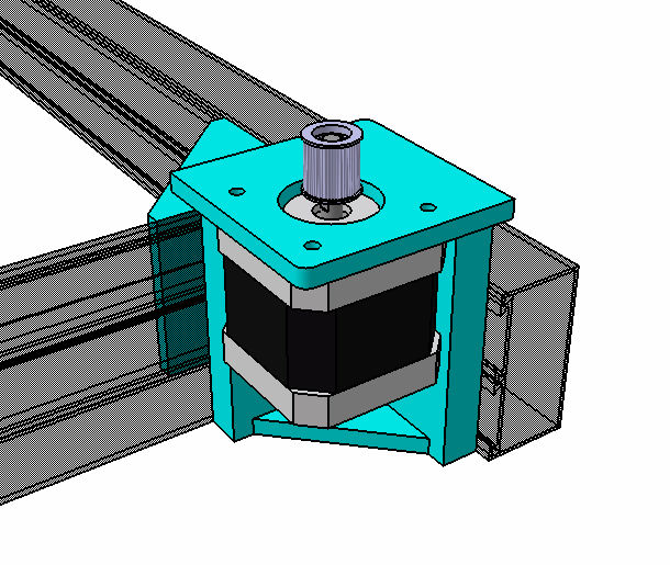
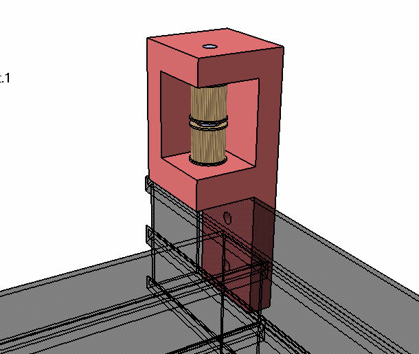
Then after everything is tested and designed, It was transferred to the fabrication team and was left for print.
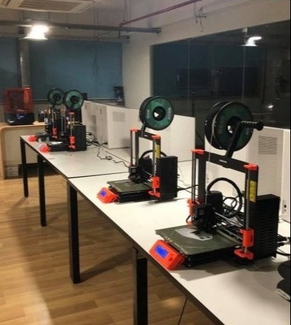
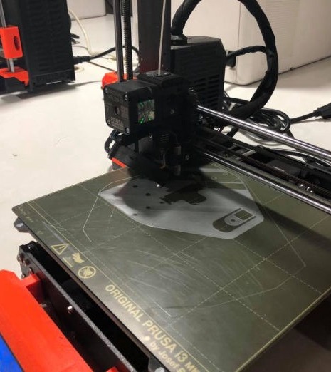
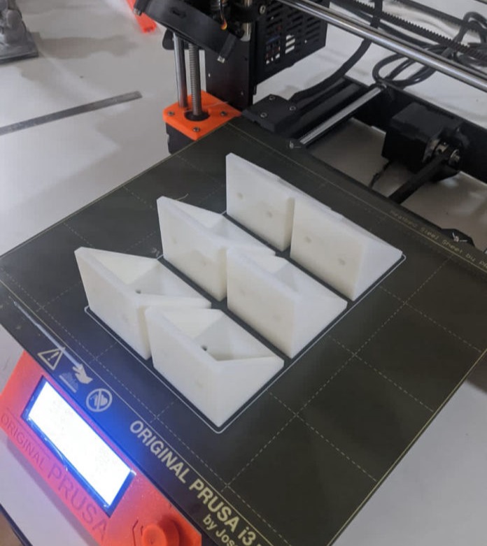
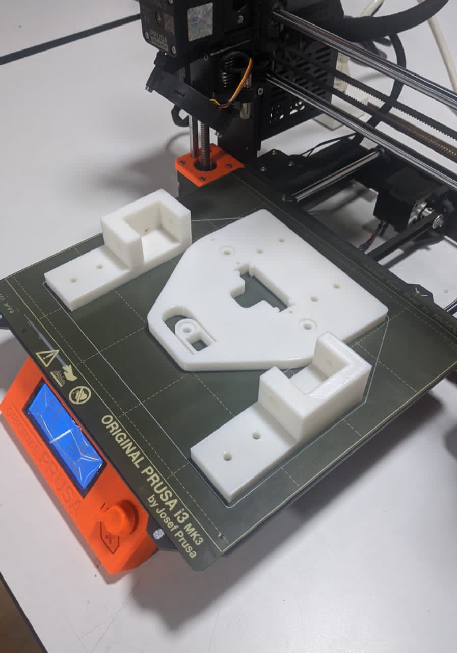
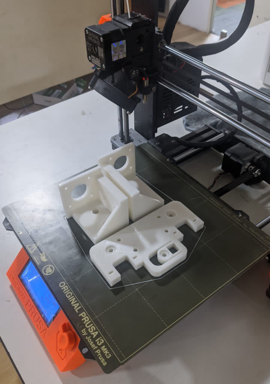
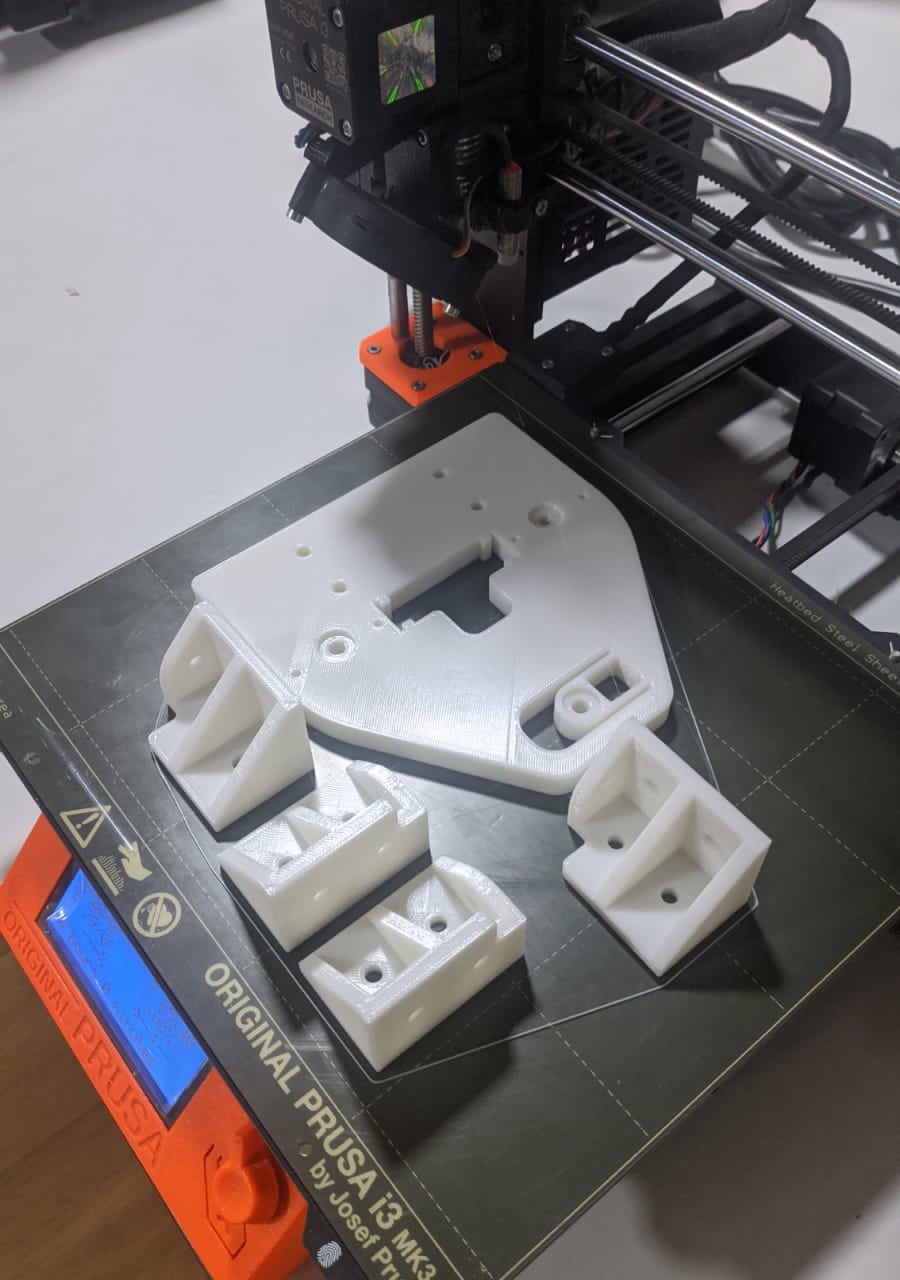
After everything was printed, I shared the assembly process and along with Abel from the fabrication team, and help from Saheen from electronics team, we assembled the main frame with sliders.
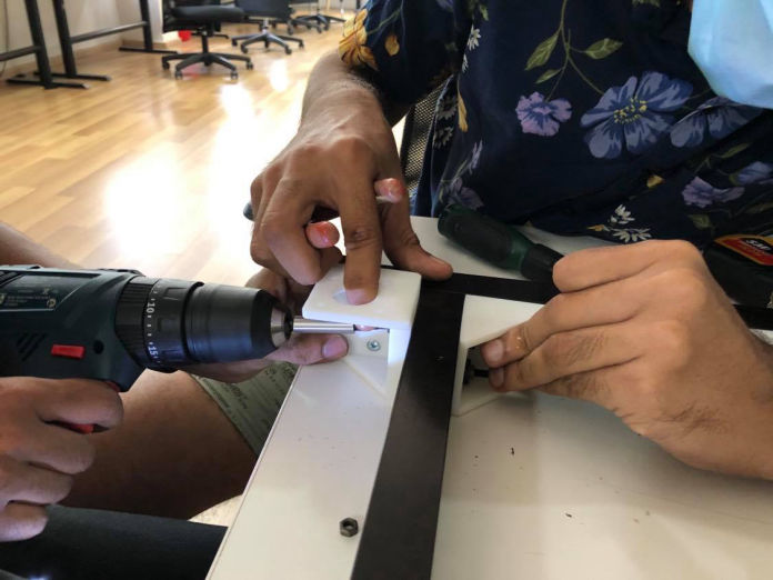
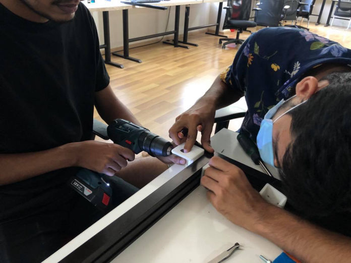
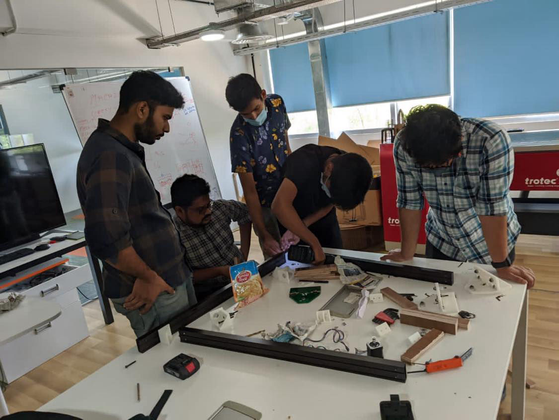
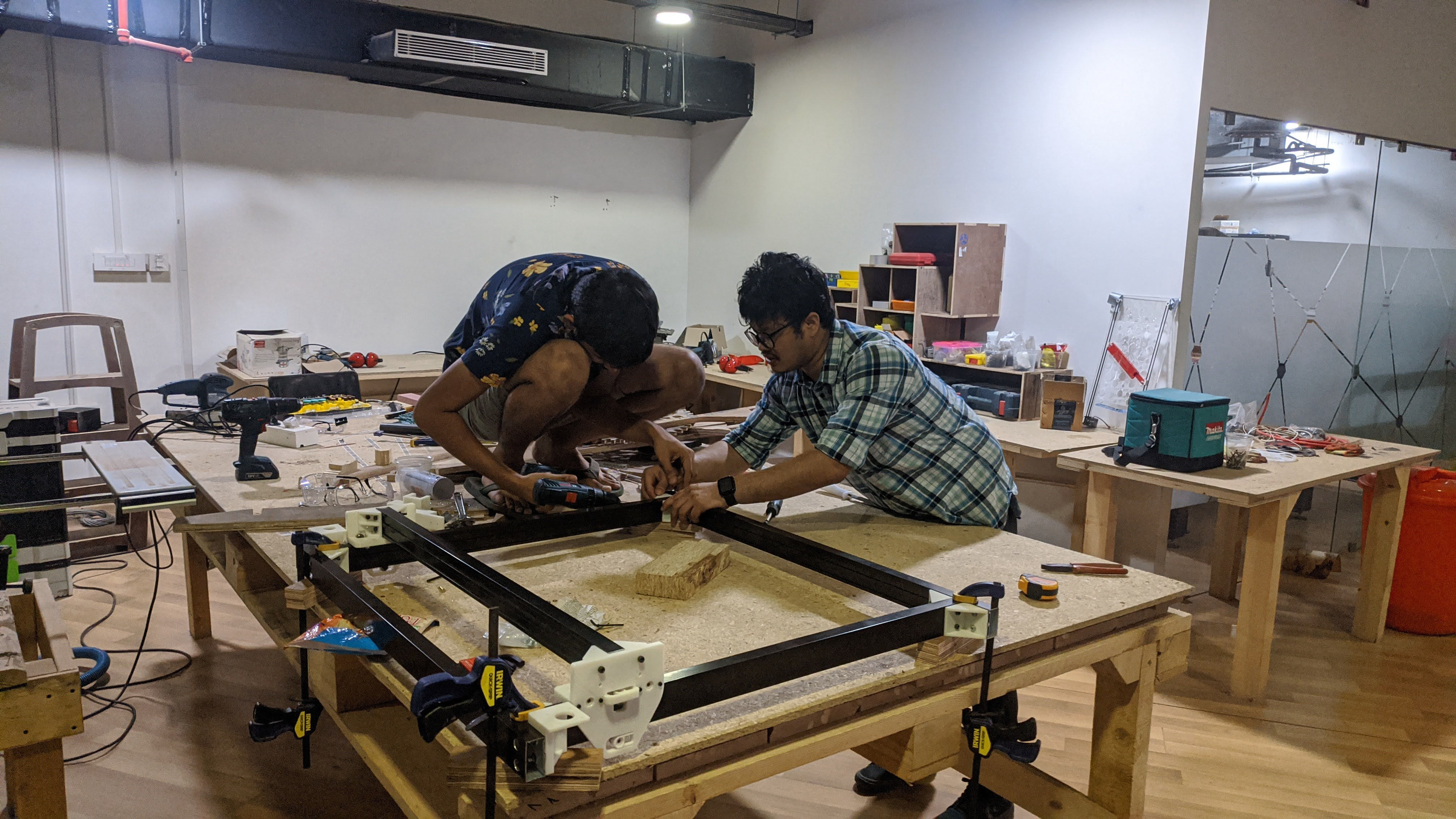
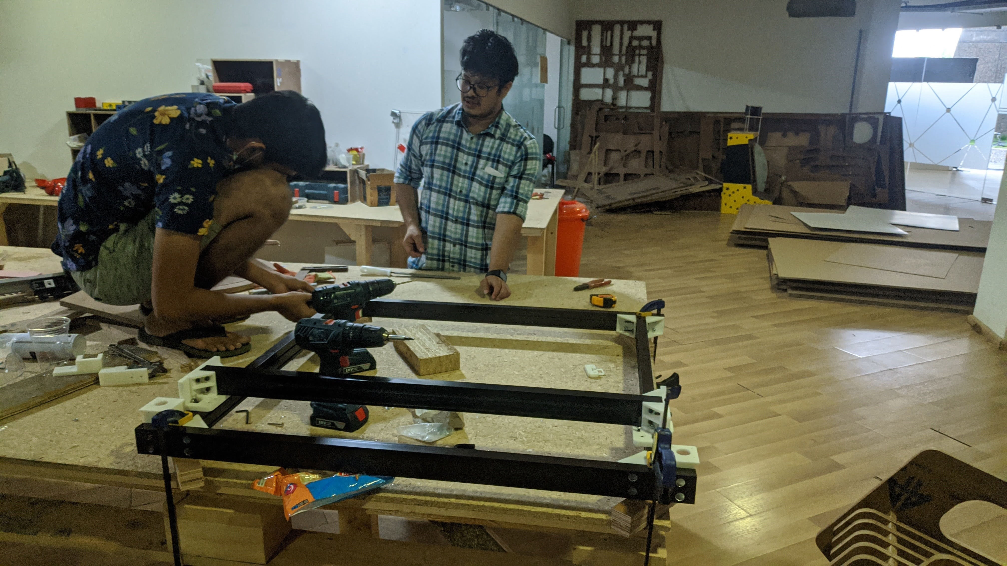
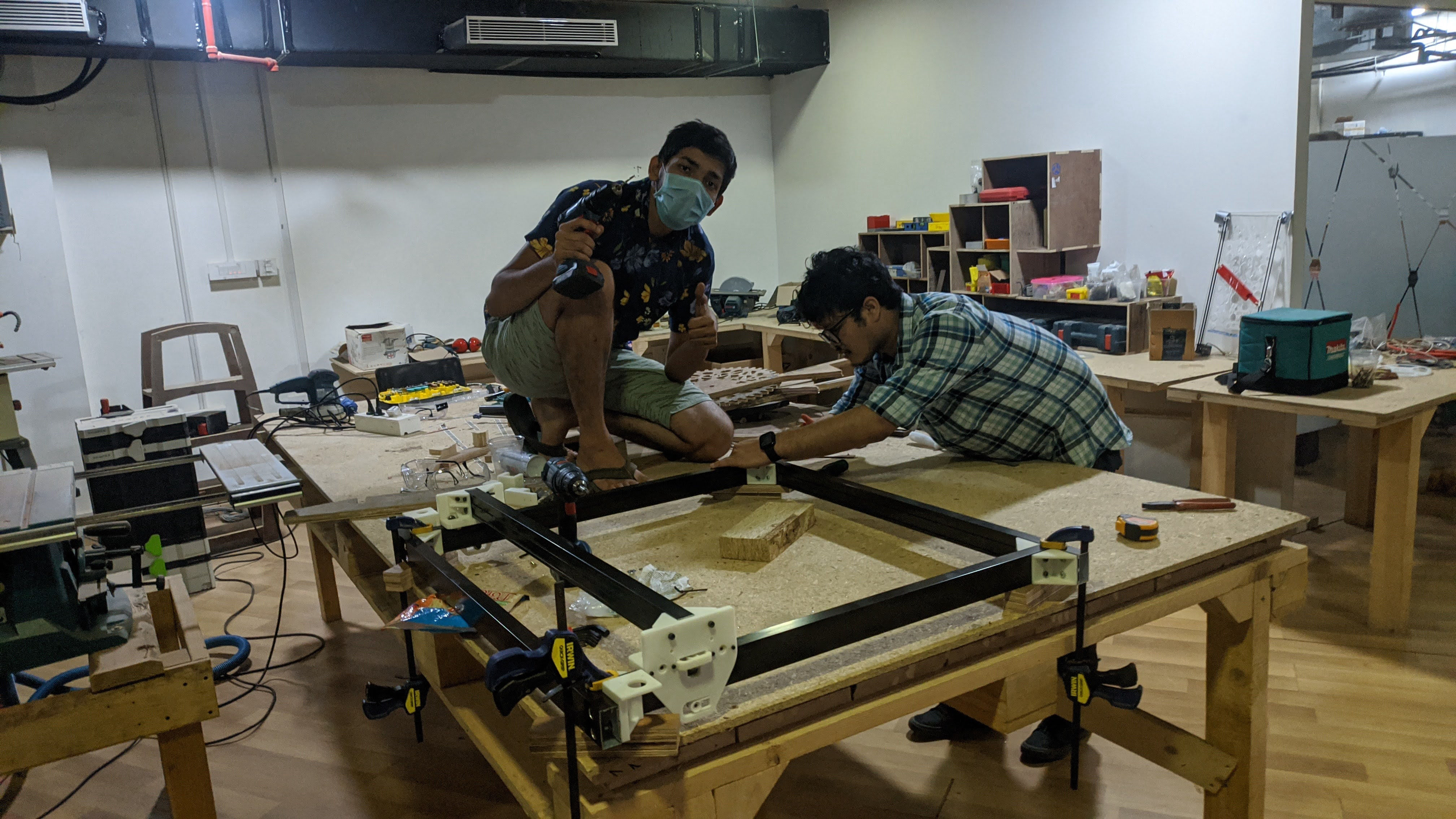
Then I came to realize that we did one mistake!!! when the gantry moves, the changing length should be linear which means that the timing belts should be straight, not in an angle. Thats why I added another correction bracket above the corner brackets which you can see below.
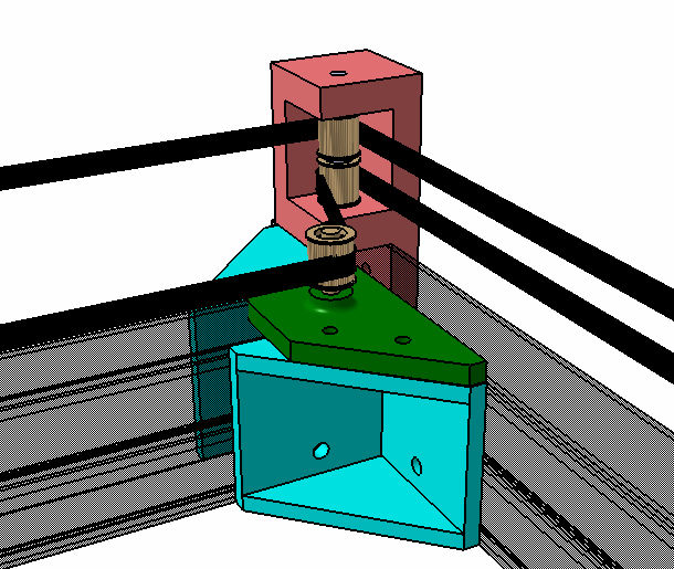
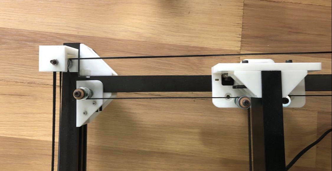
Then for the X-direction slide. vertical was modifies as the top part was not needed and the upper horizontal was added on the other side as well constraining the rotation about x direction. Here I communicated with Abhinav Ajith who was handing the end effect for the clamping positions.
I left two spots with slots for inserting nuts on the part.
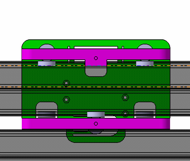
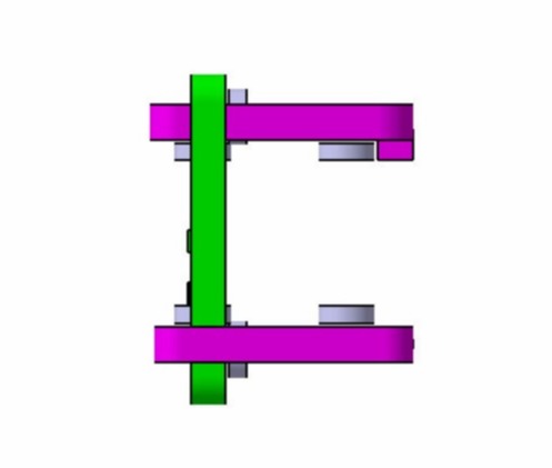
Finally, for clamping the timing belts, I added a block of plastic which would be tighened by M3 nuts and bolts. and added corrugated surface below it so that the clamping would be more secure. Similarly for the other side also added another part in between which will support the structure as well as be used to clamp the wires.
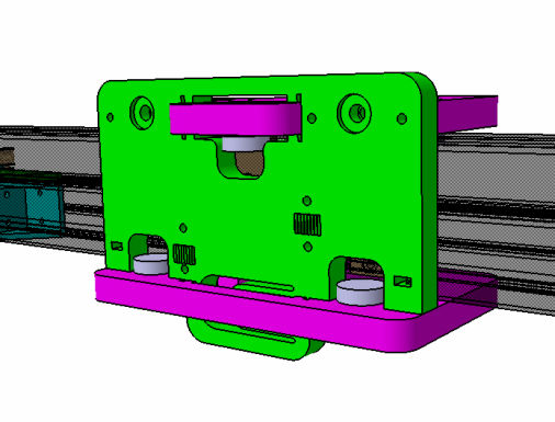
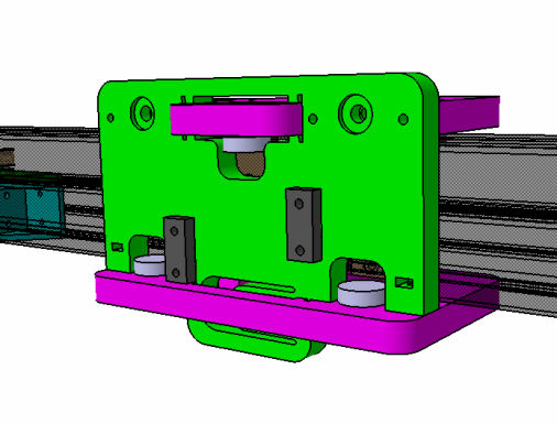
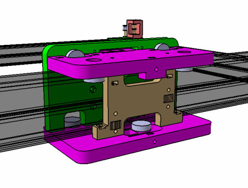
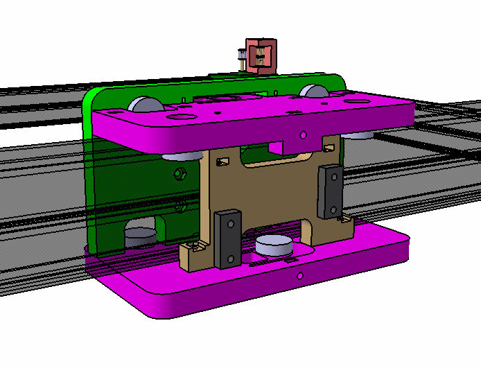
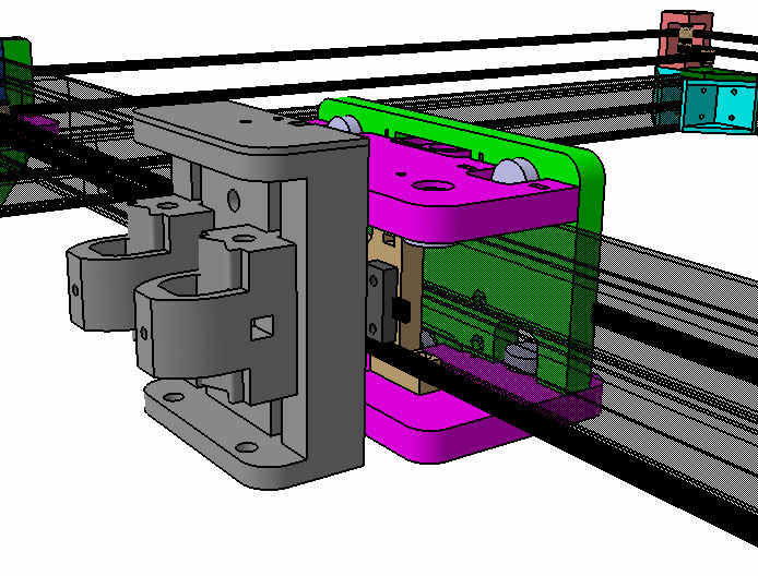
Finally, Then the machine had to be tested and handed over to the electronics team, when the legs were installed at last however the design was inspired by the legs of shopbot which can be adjusted with the help of nuts.
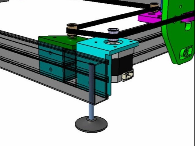
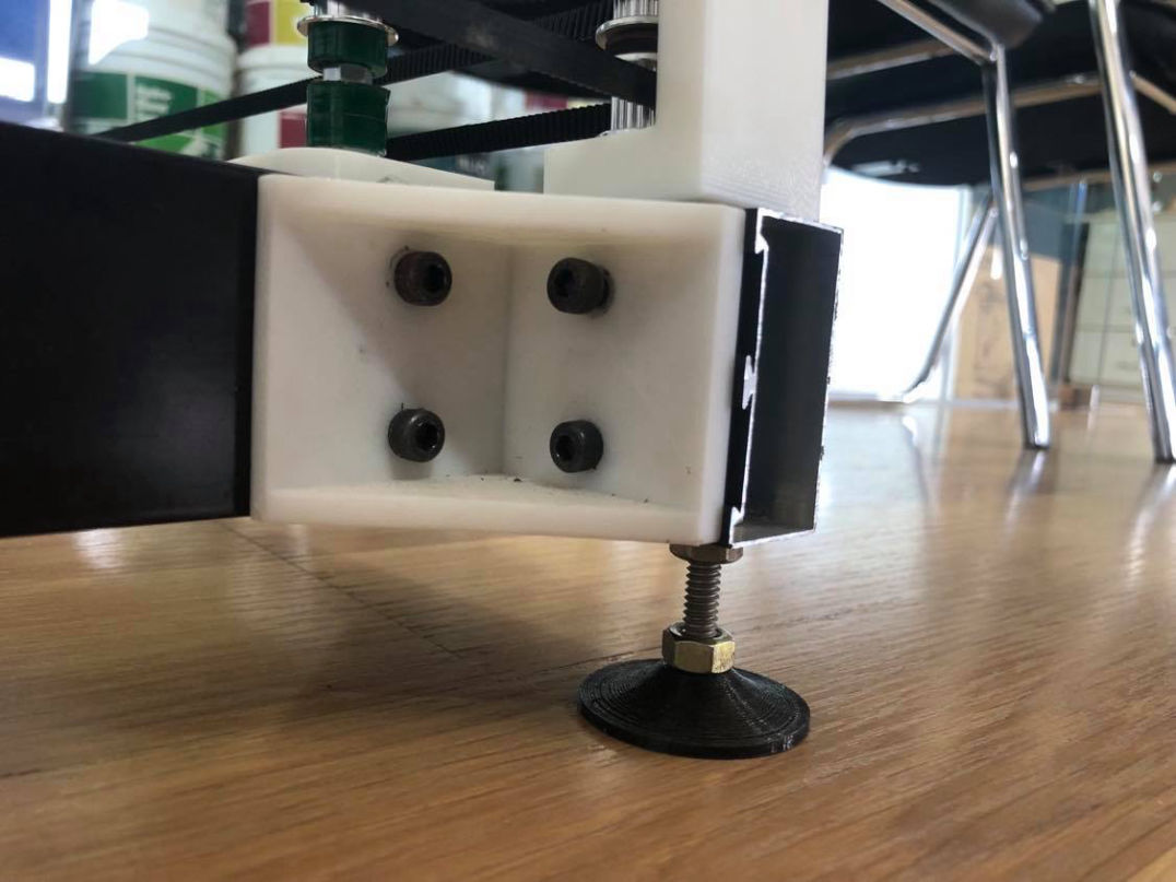
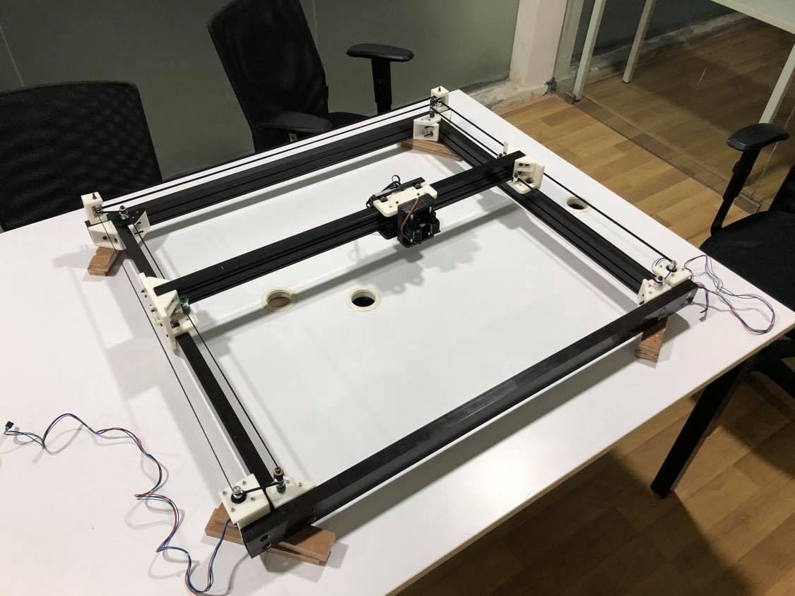
Finally Mechanical Testing was done and did full hand over to electronics and programming team.
Create a free web page with Mobirise