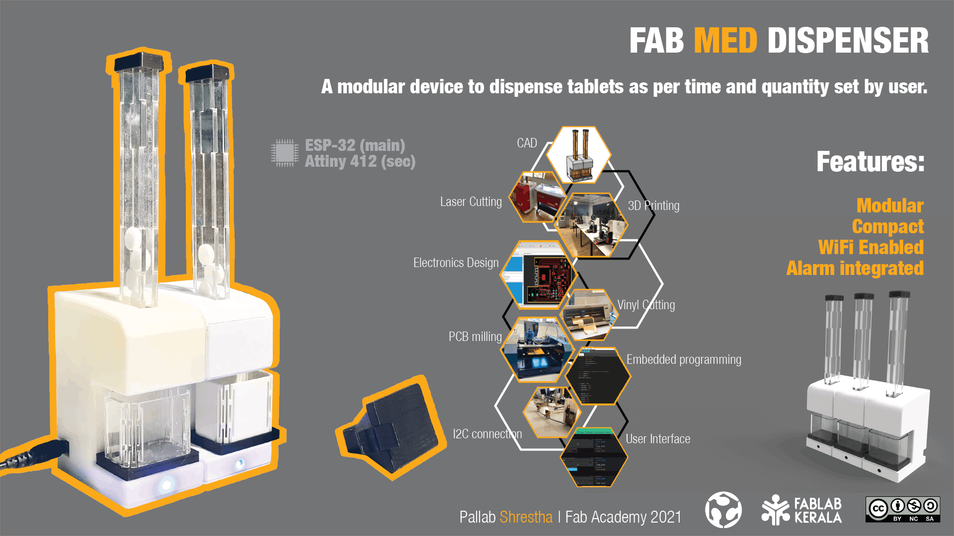
Final project that I am thinking is small but consists of most of the process that we had learned in the process during this Fab Academy. Hence due to this COVID restrictions, I tried to finalize my project with Medicine Dispenser which I am Naming as Fab Med Dispenser with model Name FMD-VO signifying version 0.
The main purpose of the proposed system is to help patients, mainly seniors and elderly people, take their medications on time in an easy manner without the possibility of skipping pills and thus reducing the risk of accidental over/under dose treatment. Failing to take medications promptly can have serious consequences on patients including delay in recovery, occurrence of other illness and even death.
People with busy schedule, elderly people and people who forget often needs Fab Med Dispenser because they often forget or tend to do so due to either age of their schedule or priority which when forgetten will or might effect your health or the effectiveness of your medication.
Designed for following aspects
1. Reliability
2. Compactness
3. User friendly
4. Assembly
5. Modularity
Device specifications
1. Size: 83mm (L) X 50mm (W) X 107mm (H) (H: 241mm with cartridge)
2. Power: 5V
3. Medicine per cartridge: 15 (Can be expanded as per requirement)
4. Tablet type: circular (13mm dia X 4.5 mm thick)
In the Box (Master):
1. Dispenser
2. Magnetic Tray
3. 5V adapter
4. Cartridge with lid
5. Hopper with lid
In the Box (Secondary)
1. Dispenser
2. Connector
Process during fabrication
Process Used:
1. 2D Design
2. 3D Design
4. Electronics Design
5. Embedded programming
Machines Used
1. Laser Cutter
2. 3D printer
3. PCB milling machine
4. Vinyl Cutting
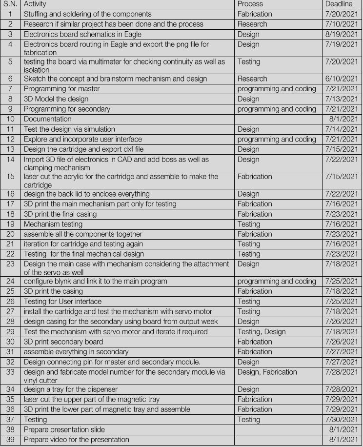
I used miro board for planning the project. It is very easy way to plan the process and for managing it. It can also be used for collaboration. I used KanBan template for my project planning
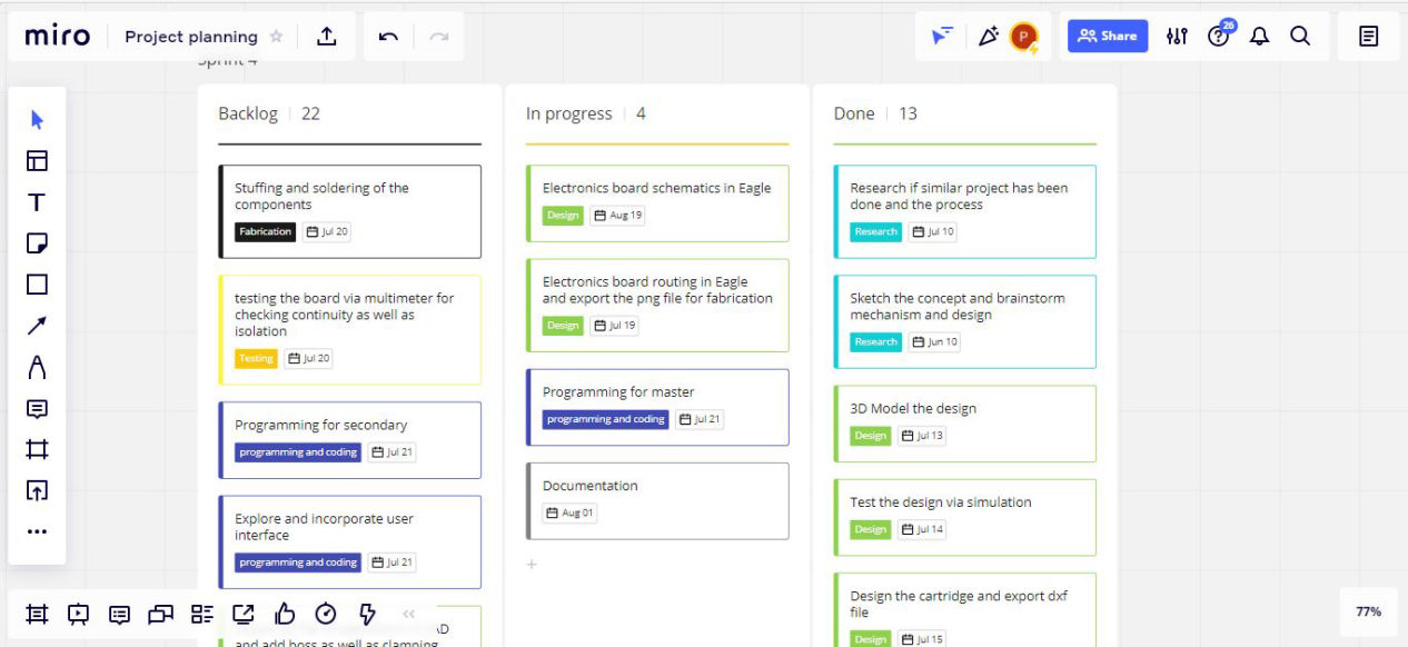
We can also export the whole planning to excel file as well.
Main planning for the working mechanism
1. Will be using servo motor for powering the whole mechanism.
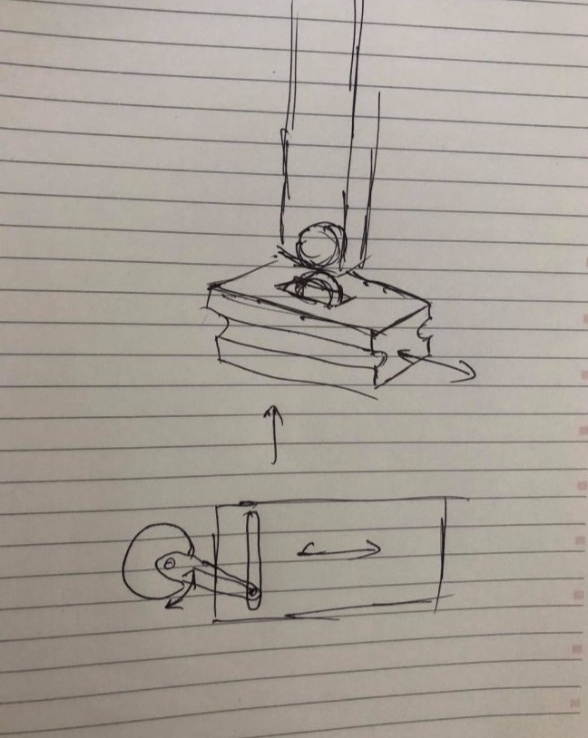
2. Scotch yoke mechanism will be used to dispense the Tablets
3. Wifi Enabled microcontroller will be used.
4. Signal will be given when medicine is dispensed via hall sensor.
CAD design (2D and 3D)
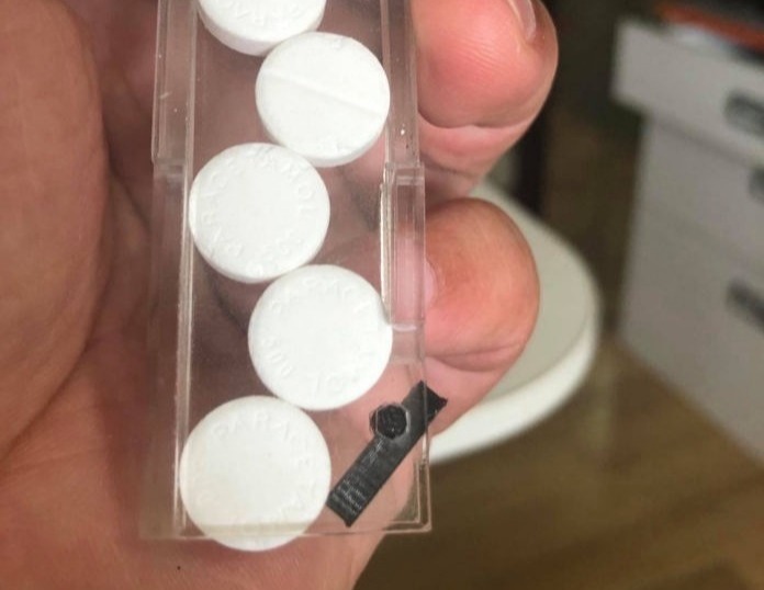
First thing to do was limiting myself with design constraints as we cannot design for everything at once. So i selected the tablet size for the design. As paracetamol tablet was cheapest to test so everything that is designed hereafter are for the tablets of size (13mm dia X 4,5 mm thick).
Selection of mechanism for dispensing:
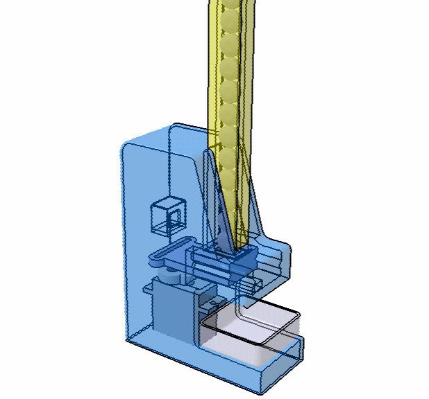
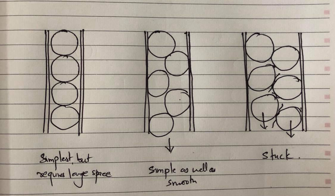
Then for the selection of the mechanism, I referred to different models among which most has used the horizontal orientation of the tablet. But, I was not happy with it. The reason is that. If the minimum cross-section is not used while sorting then there might be a possiblity of two meds getting stuck in the outlet
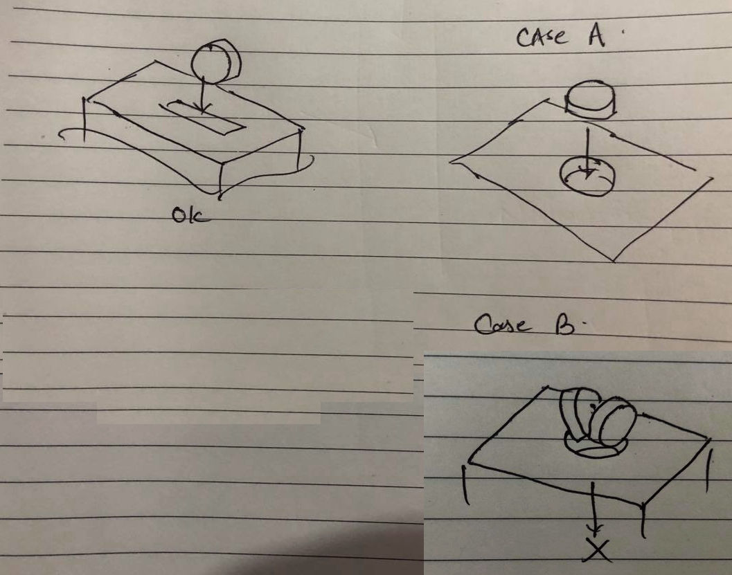
Hence I decided to go with the smallest cross-section that the tablet has and designed accordingly. Now for linear reciprocating motion for the ejection of the tablet, there were options like directly using servo arm to push the medicine. Or rotary motion which moves the tablet in rotation ad ejects when there is an outlet in the rotation path. However dew to space and design concept, I decided to use the Scotch yoke mechanism which converts the rotary motion of the servo to the linear motion. And this was just perfect for me
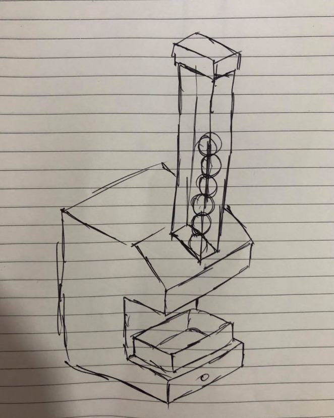
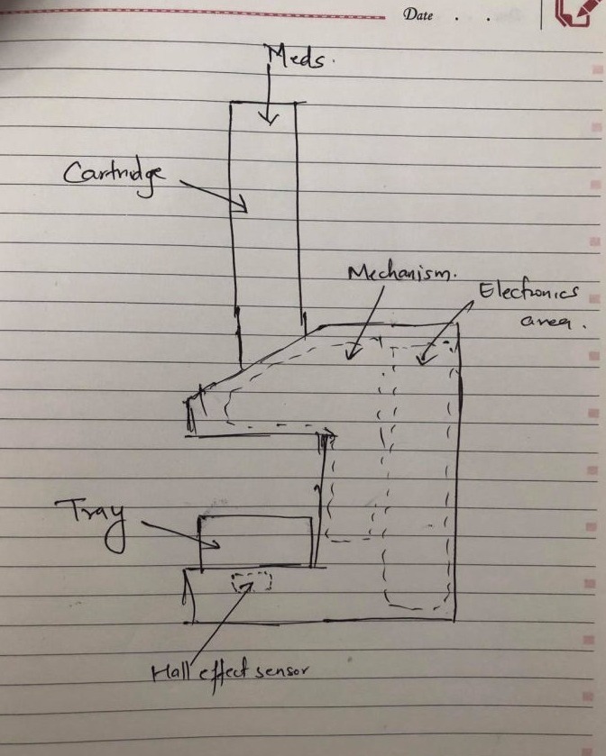
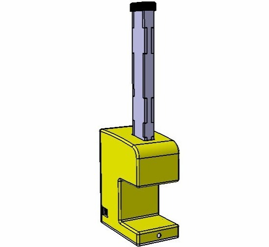
As we were in lockdown for 2 months During that time I focused on the 3D design and animation from where i can get some insights if there might be some problem. Following are the initial sketch of the models
Selection of Mechanism:
I reviewed different mechanisms which uses
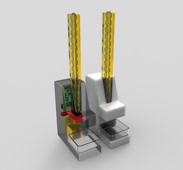
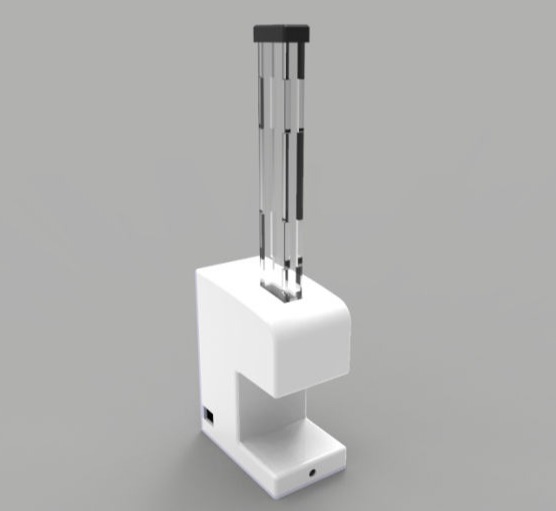
Then the 3D design was done so that animation can be done and simulated to know about the feasilibility. Following are the screenshots of the first iteration of the model
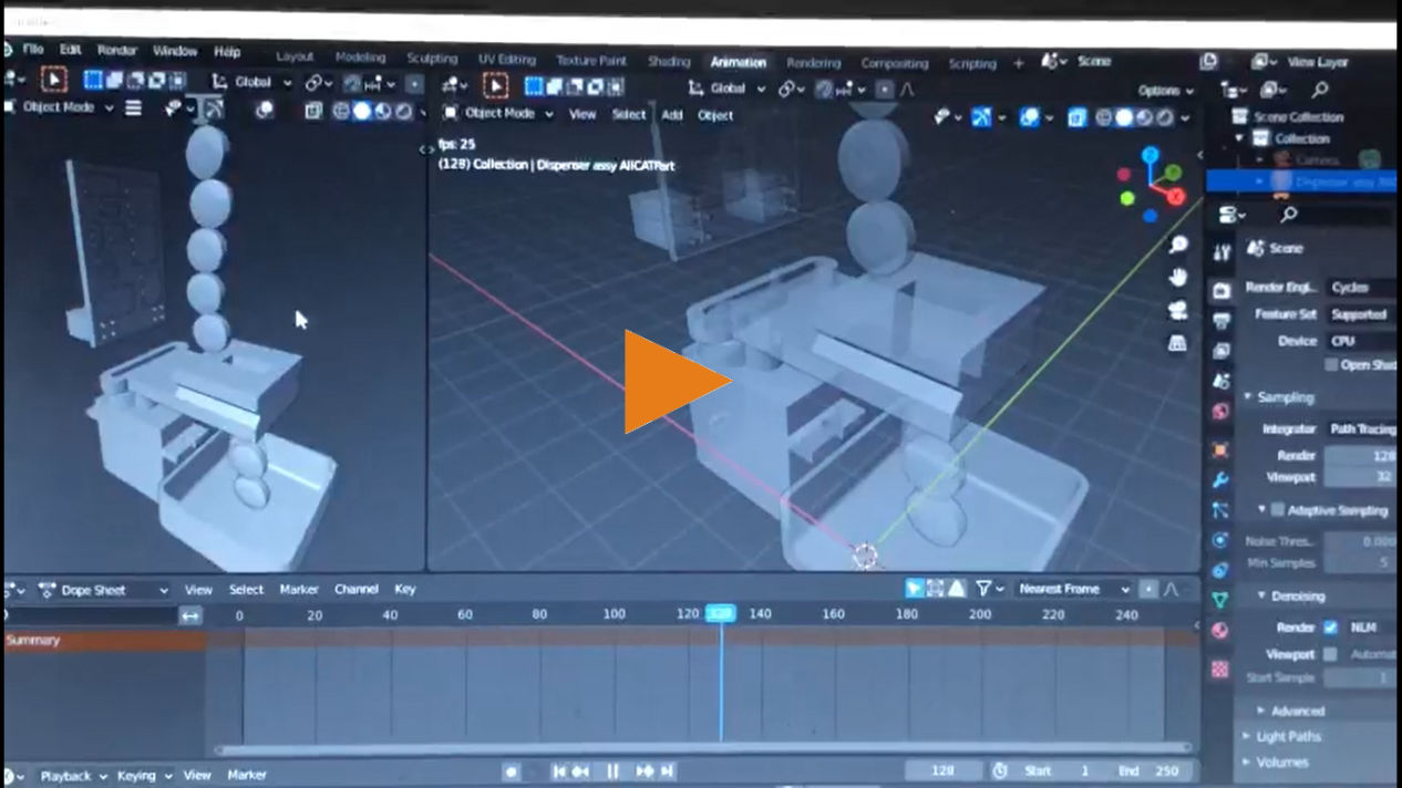
Then after the CAD Designing and modeling was done, I exported the STL file to blender to use physics and see how it performs when animated, I used only gravity for the medicity. Main casing as the domain and added reciprocating motion to the slider which gave the following result.
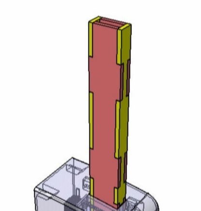
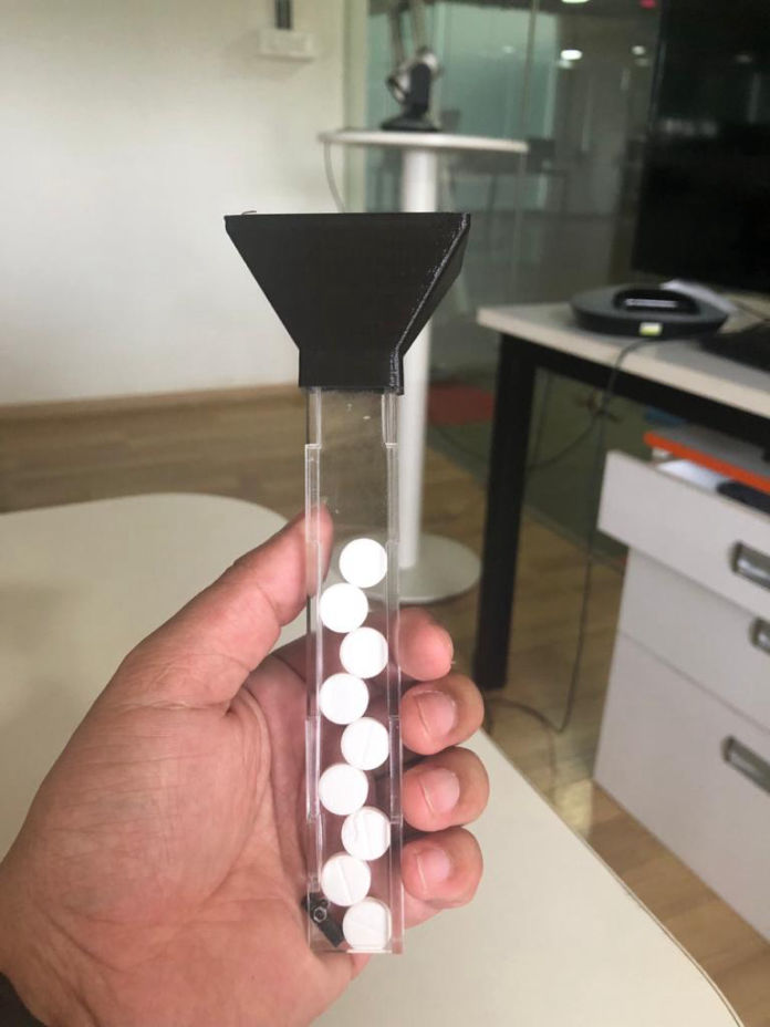
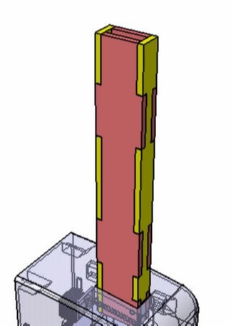
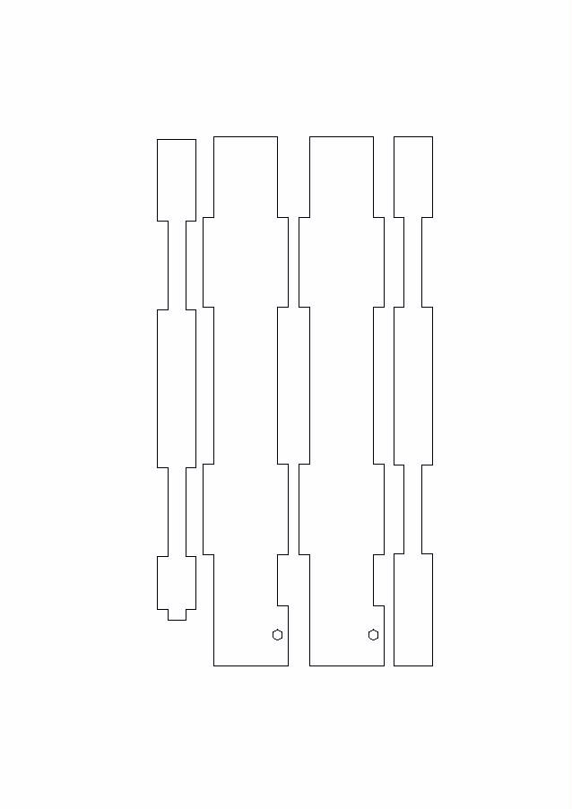
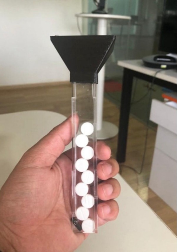
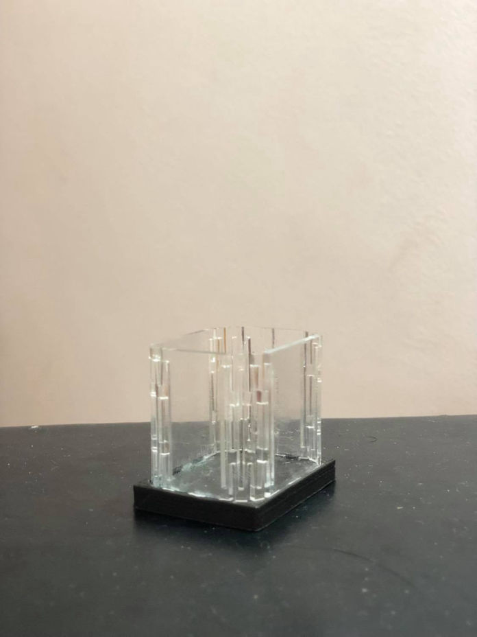
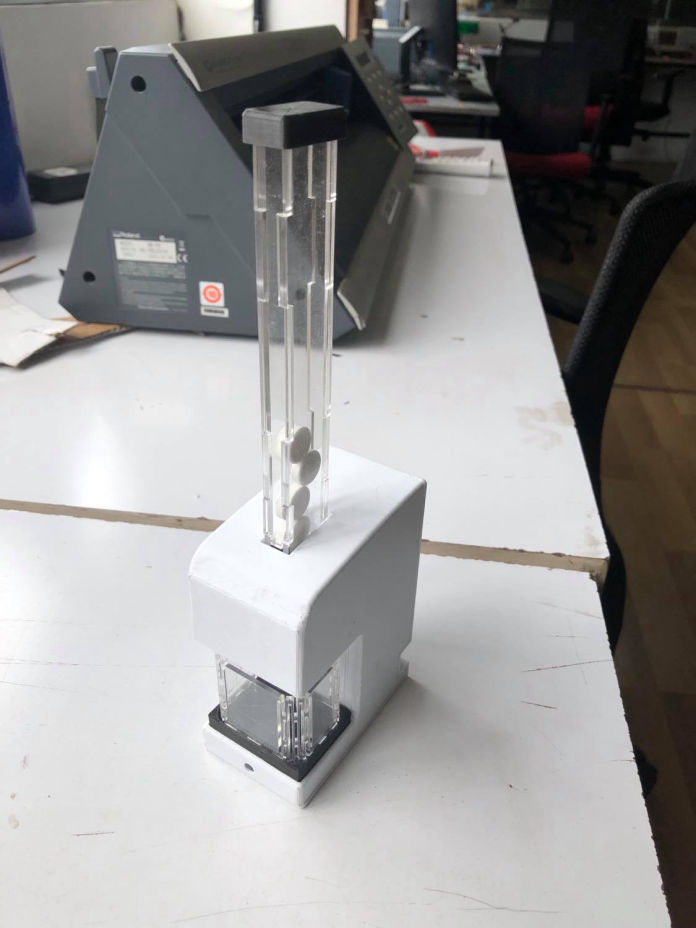
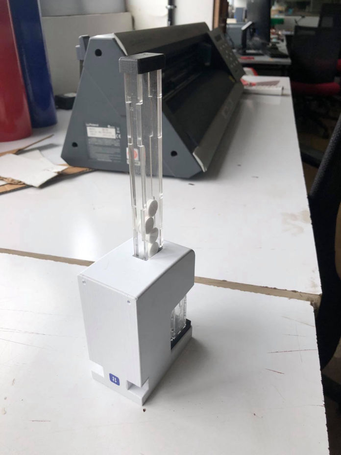
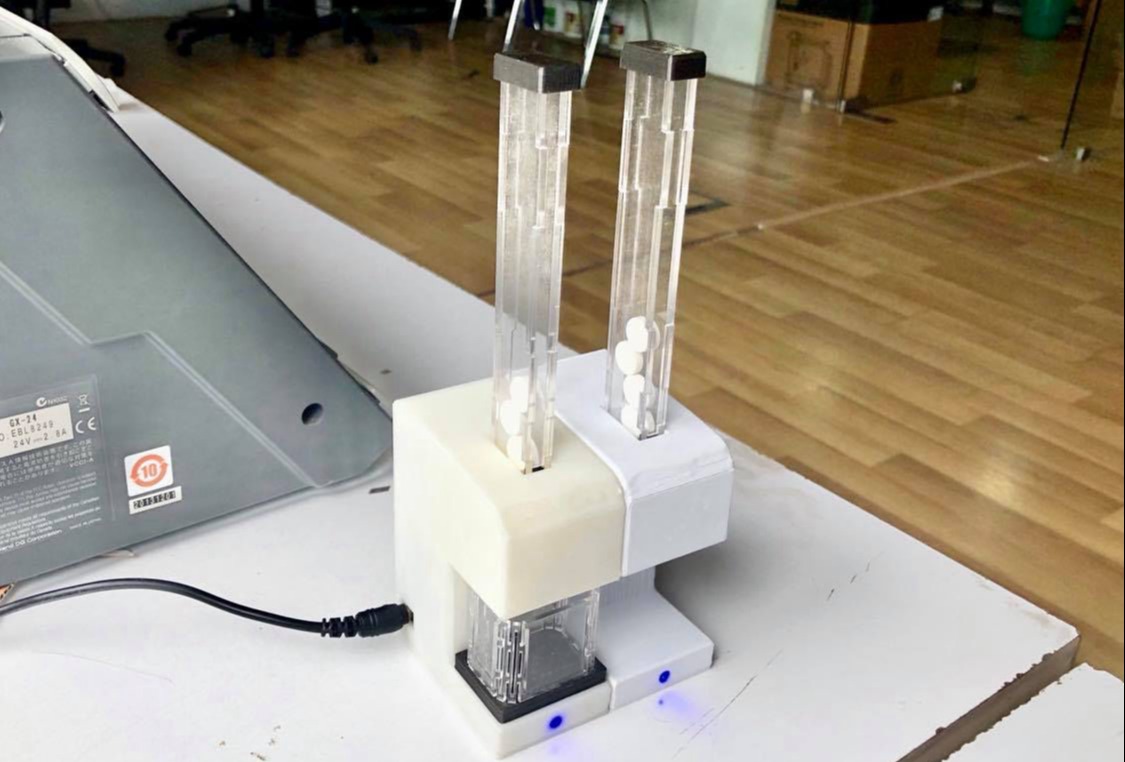
While I was designing the body, I was also parallely designing the cartridge, I am thinking about using the transparent acrylic sheet and lasercut it and then assemble to make a cuboidal hollow part. The reason for making it transparent was that the tablets could be seen from out and when it is empty, can be refilled again. And using laser cutter, if is faster for fabrication as well as the length of the cartridge can be increased as per our requirement as well.
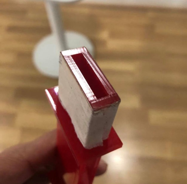
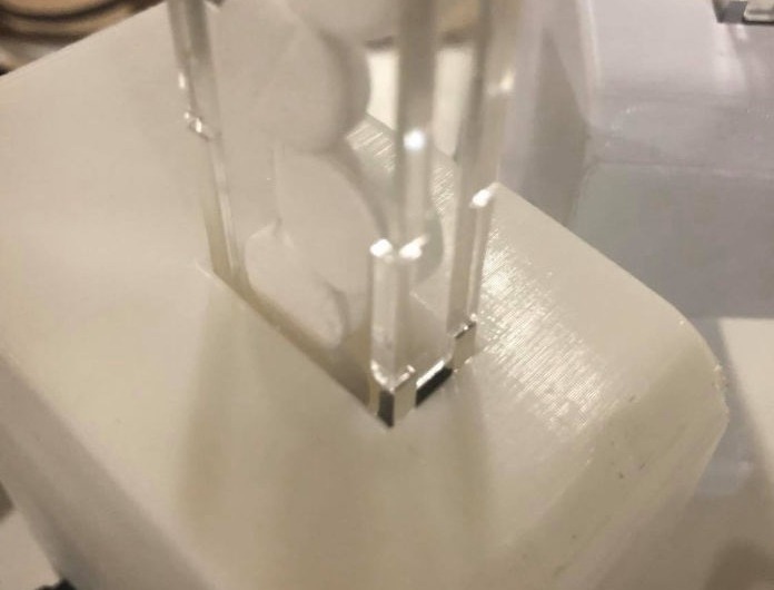
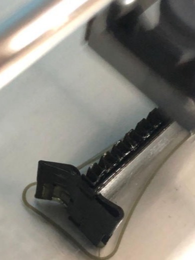
So after the Lab was open, Time to protoype the mechanism first. So, as I wanted to have as much tablets in the cartridge, I had to find the spot up to which it can be kept in zig-zag position. So i wanted to test the width of the cartridge first with the just the dispensing part.
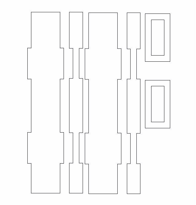
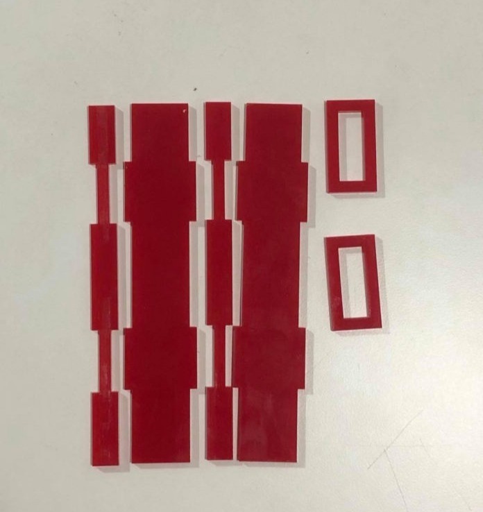
Then I made the dxf file from from the 3D CAD design and following the process, laser cut was done in 3mm acrylic sheet. First time since it was just a test, red acrylic was cut.
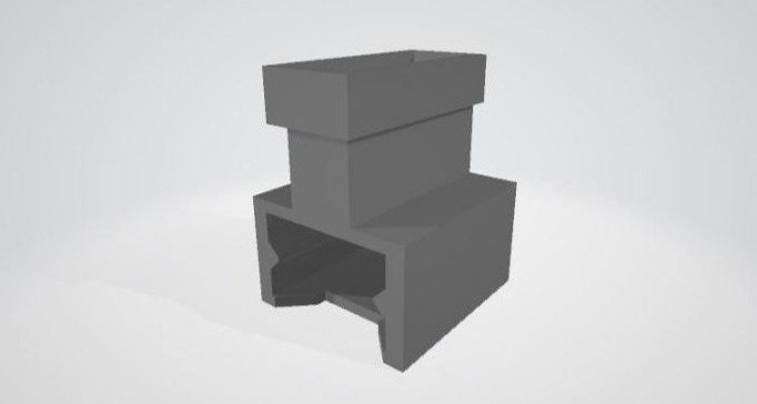
Following this, 3D printing just for the specific sliding mechanism was done to test the smoothness of the slides and also the cartridge.
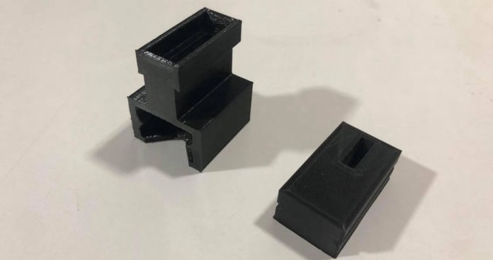
Following this, testing was done for from where there were some times when the tablets were stuck. Then a space was made from the laser cutter itself and then placing the prototype from where I found the problem and aslo the actual width that should be used for the cartridge.
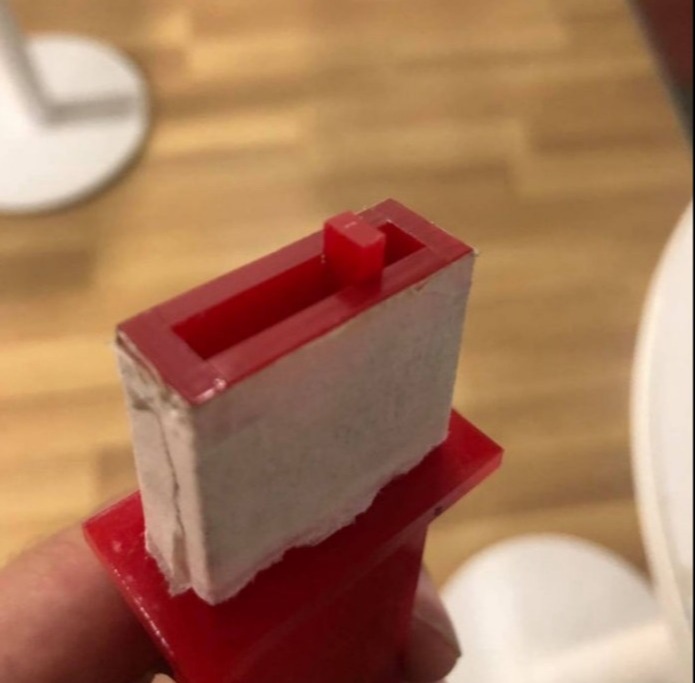
problem during testing
Then after placing spacers the dimension for the cartridge was found to me 18mmX 5mm (Inside dimension). FInally the slider and mechanism was working fine that you can see on the following. Then a transparent acrylic was cut for the final as well.
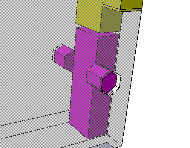
Then after the mechanism was done, the issue that i had was how to hold the medicine during loading to the product. So i was thinking so complex but simplicity is the key and simpler the design better it is. so I came up with simple idea to add autolocking part which can just be inserted in the laser cut acrylic while assembly. The design is shown in the following figures. Here the add on should lock on six different locations in one full rotation however we don't need that much
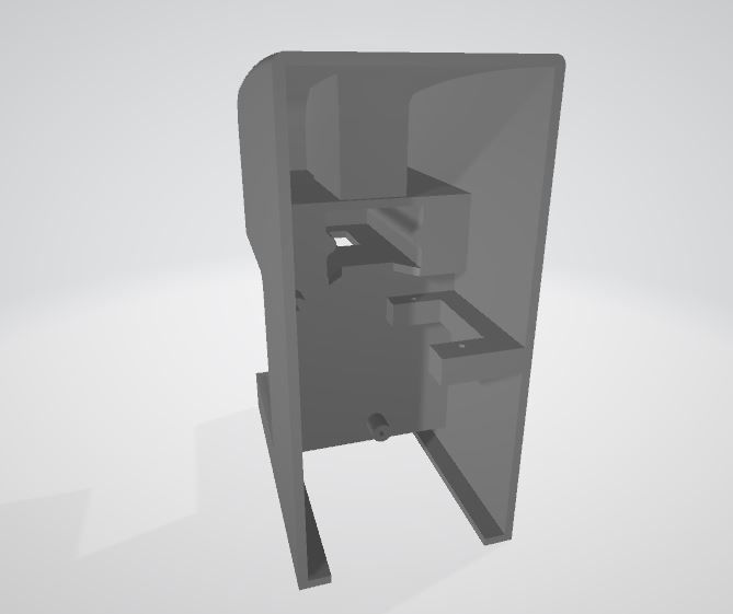
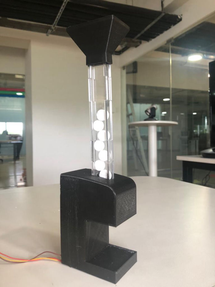
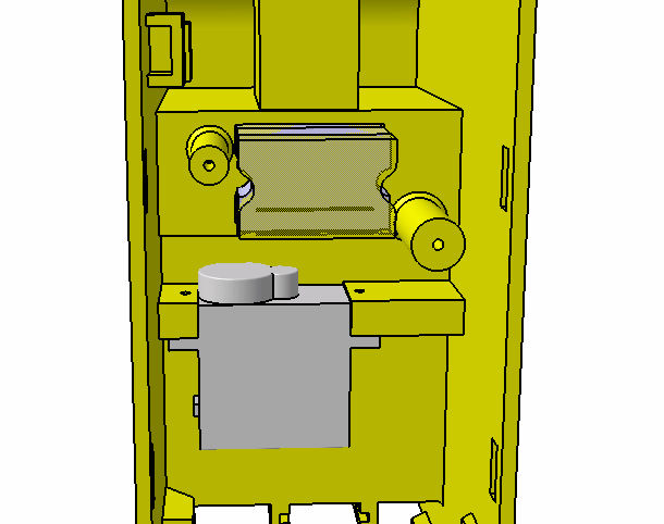
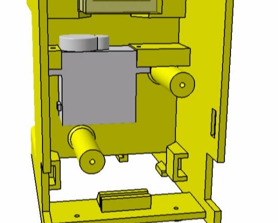
Parallely, Main casing design was done where the tested mechanism was included and other things like motor placement was considered on the first prototype of the casing. The purpose of this was to install all mechanical and moving part in casing from which i can move to electronics. Here first, the testing was done with motor orientation longitudionally.
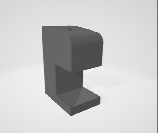
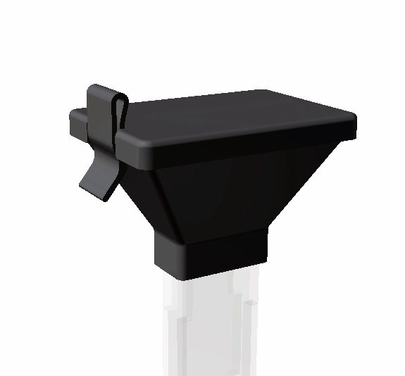
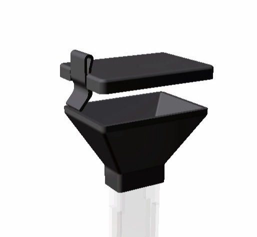
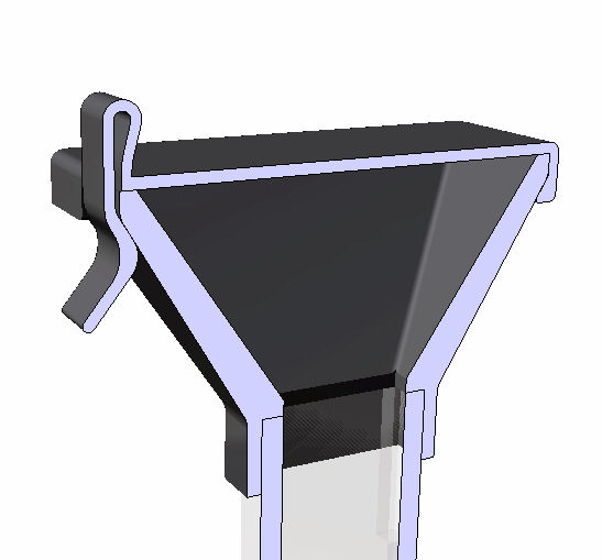
Parallelly, as it was hard to put tablets one at a time, I designed a hopper with a lid. This will be given to the consumer with the master unit. This will only be used when the user loads the medicine. Same hopper can be used for multiple modules.
For designing the lid, A U type cantilever snap joint was taken as reference. the 3D hopper and Lid can be seen below
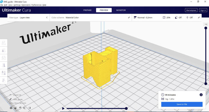
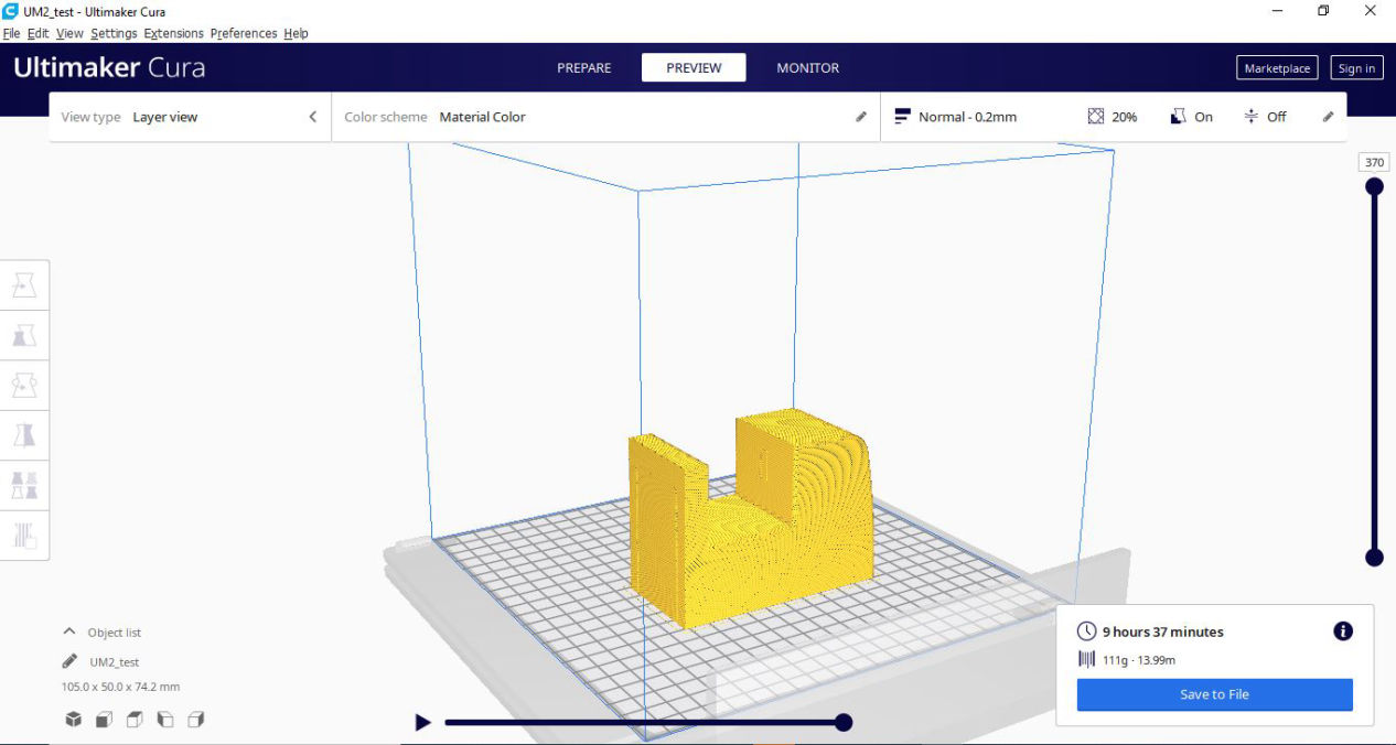
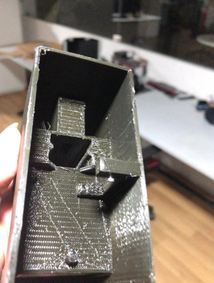
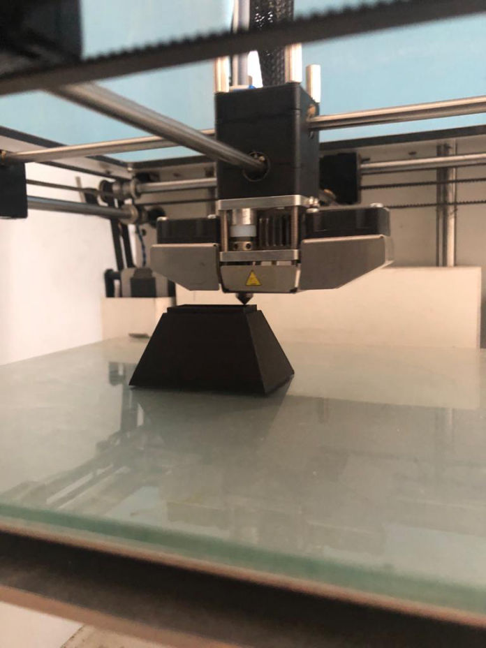
After everything was design, it was exported to stl file and the slicing was done with higher layer thickness as this was a prototype. Then all the parts were printed.
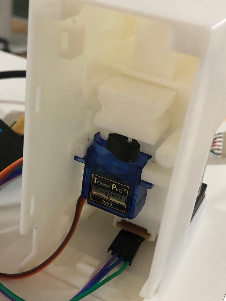
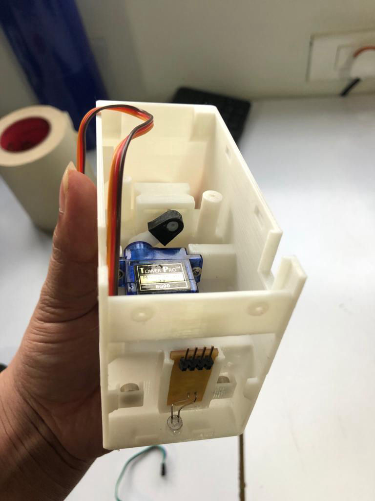
Parts were taken out and assembled, and servo motor was also installed and for the lever from the motor, I 3D printed part which goes to the motor and also stick into the slider of the dispenser.
Here I found out that the motor also can be rotated 90 or placed laterally, hence making the space more compact and product small as well as provide rigidity to the motor while operation. Hence, I reflected it in the final one. Then I tested the dispenser by giving power to the motor and yes it was working, It took time to tune the servo for the best overlap for intake and exit holes but finally, mechanical testing was a success.

Electronics Design
After the mechanical design had been 90% completed, I moved to electronics design. In electronics design, I had planned using ESP-32, a buzzer, a servo motor obviously for powering the mechanism, a hall sensor as an input and i2c for the communication to make it modular. And for the secondary, I planned to use same devices but in place of ESP32, I will be using Attiny 412 as a secondary module.
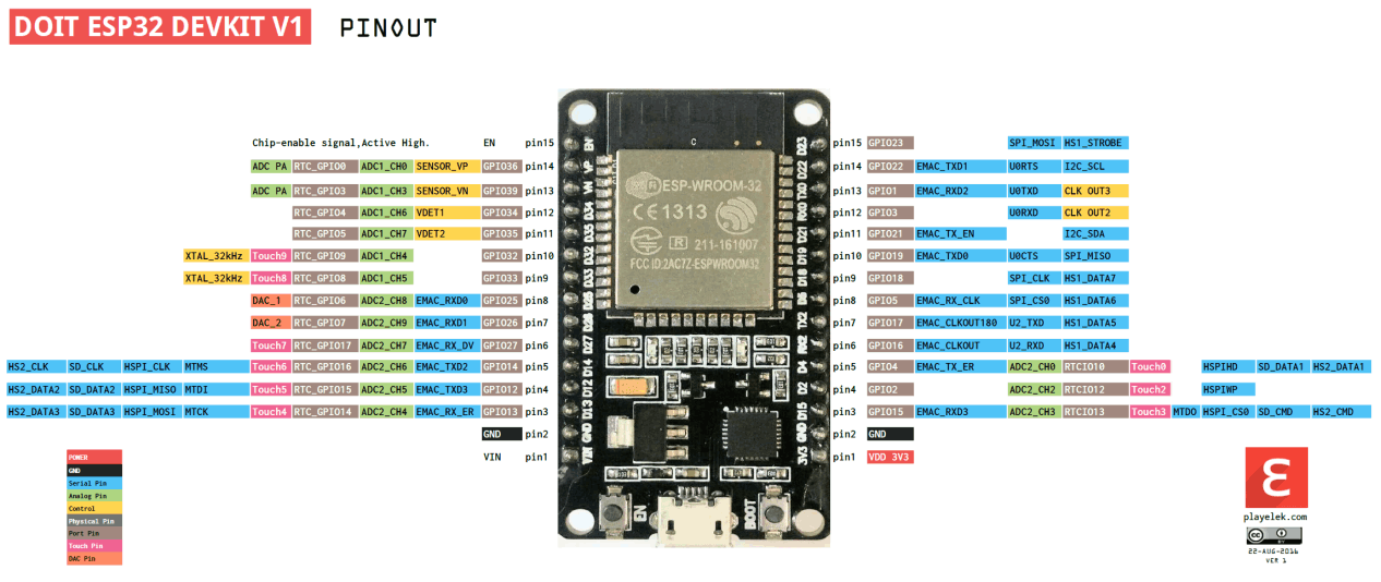
First thing to do is study and know abut ESP32 and the pins which i will use for different IO devices and communication. Following is the pin diagram for ESP32
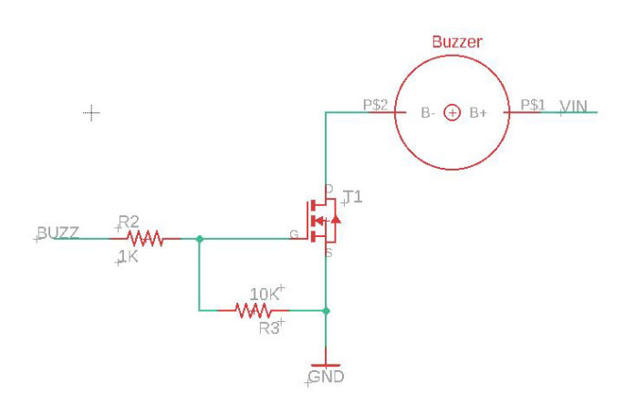
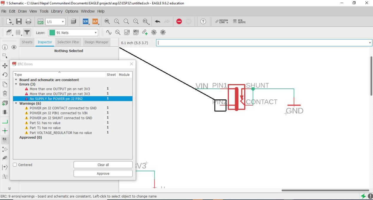
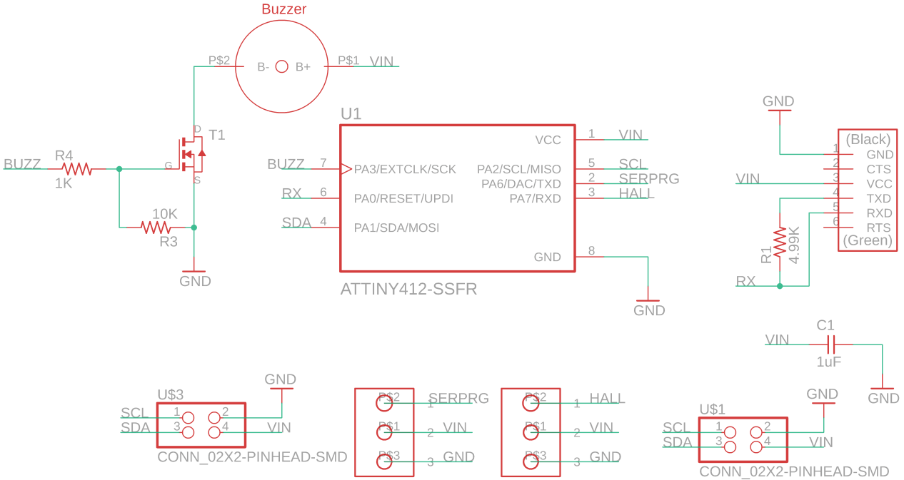
Then, I started with eagle, and started the schematics straight where hall sensor component, buzzer, servo unit with leds and ESP32.
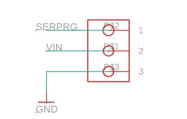

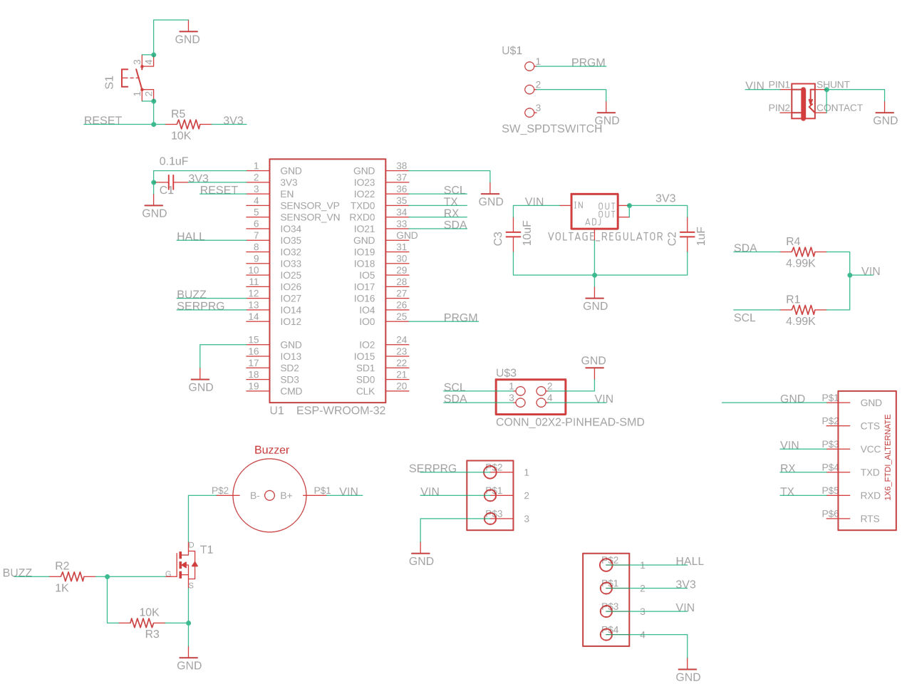
Here slide was inserted because in flashing ESP32 we have to keep on pressing while the program is uploading so it is good to have SPDT switch and a push button on the boot or reset button. Also since ESP32 works on 3.3, a voltage regulator is added. For servo and hall sensors, pads are made so that THT type male pin header can be inserted here and the servo and hall sensor can be connected from back. (Update: I forgot to add pullup resistor on the board for I2C while fabrication so added it on the secondary, but it is always good to have it in master so updated the board putting 5K resistors as a pull up resistor for SDA and SCL)
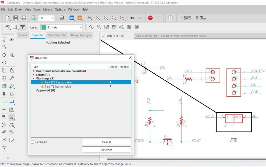
Similarly for buzzer as well, two hole were made for the rivets so that it can be soldered from back. Then the ERC was clicked which gave couple or warning and errors, I was panicking at that point but, every thing was OK and could be approved.
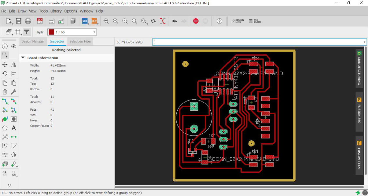
Then after all the schematics is OK I then switched to the board. Then set up the design rules of 16 mil and then was arranged. Luckily, Saheen made a library for ESP32 processor which can be milled by 16 mill bit. I was also doing an i2c connection here, so added 4.99K resistor and 4 pins for communication to the secondary boards. After lots of auto route rearrangement, manual route I finally came up though the route and placed two places to clamp the board.
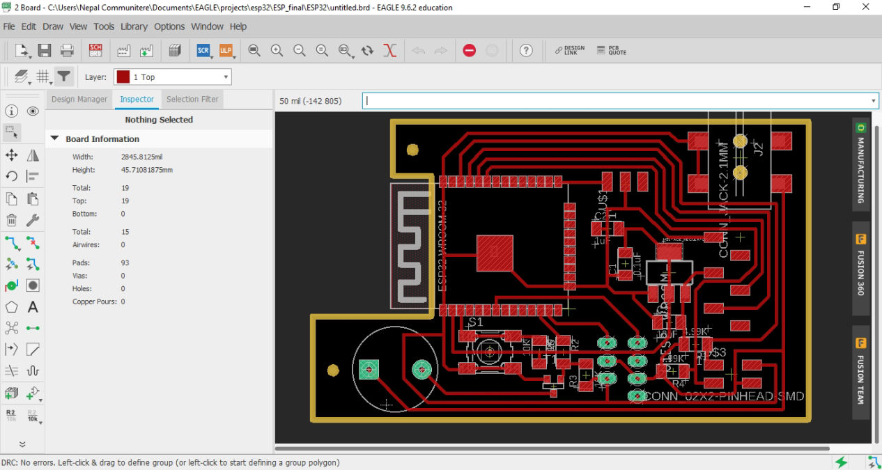
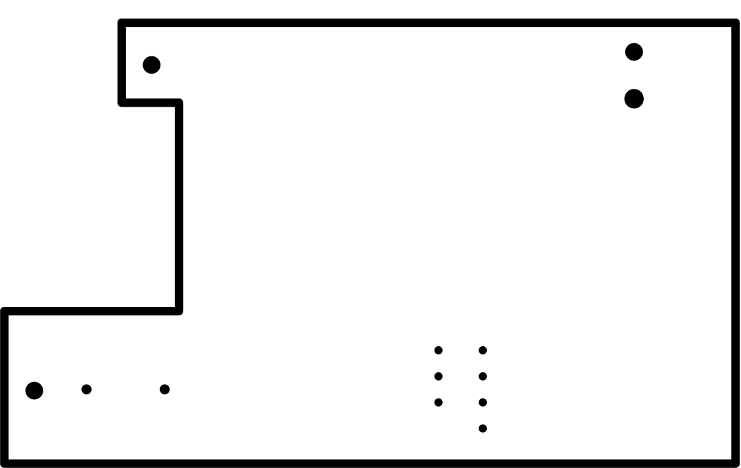
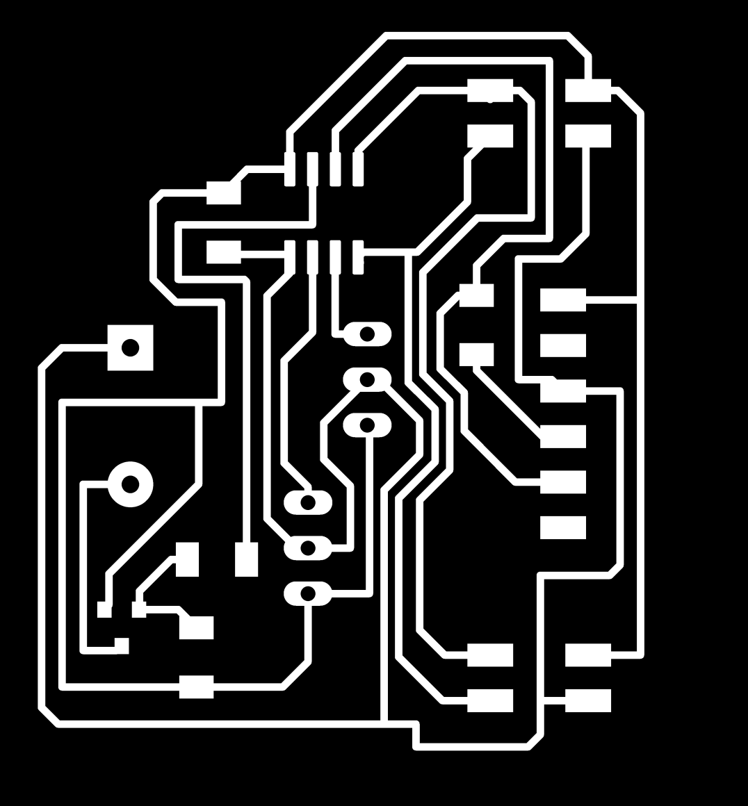
Following are the traces and the trim line for the master board
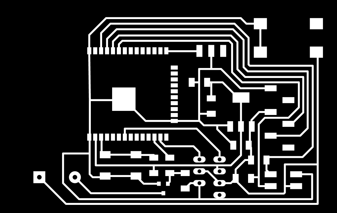
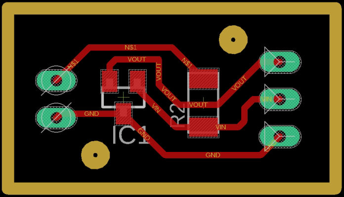
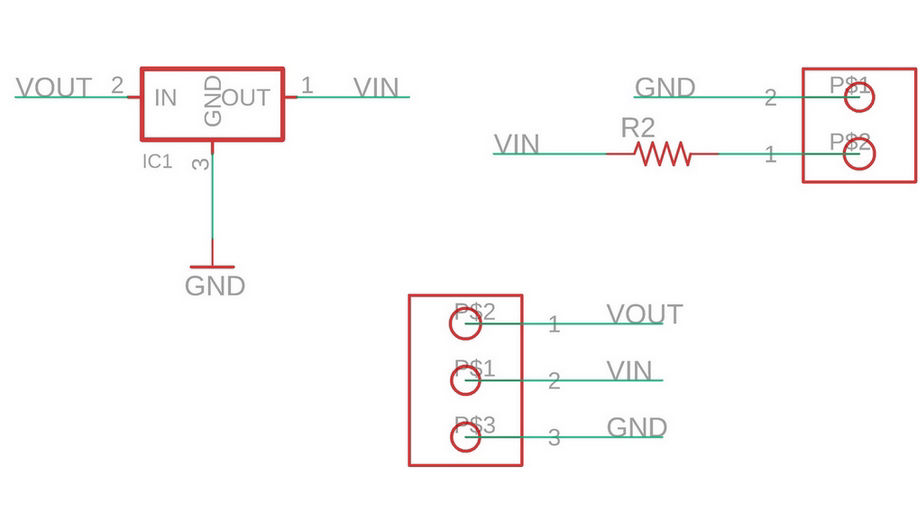
Similarly, Schematics for the hall sensor module was done. Here 5V to 3.3V logic level converter was used since the supply voltage for the hall sensor was 4.5V to 5.5V.
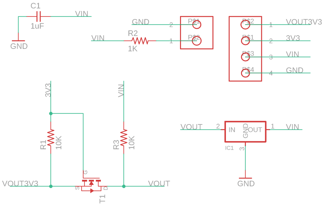
Then after all the schematics is OK I then switched to the board. Then set up the design rules of 16 mil and then was arranged.
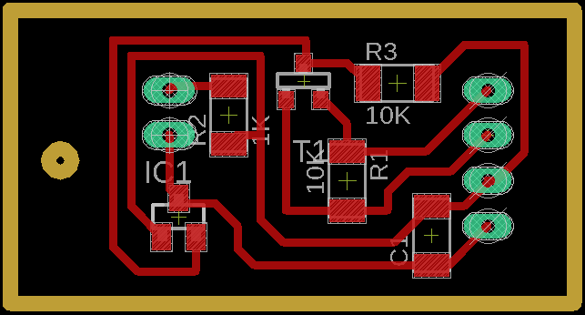
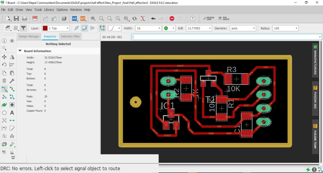
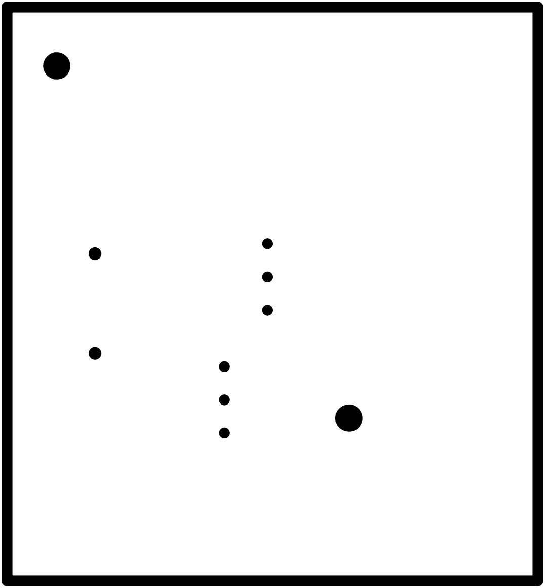
Following are the traces and the trim line for the master board
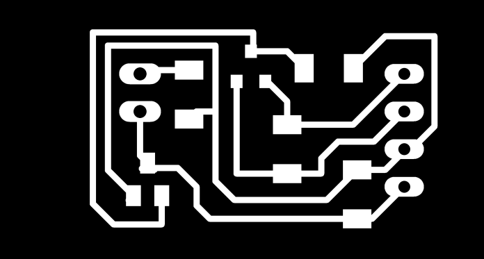


Here holes and trim is separated because, when it is sent together, it cuts the trim line and cuts the hole, during which the board moved. Hence, like other manufacturing process as well, trim has to done at last.
Similar to this secondary bards have been done for output week which you can goto from this link. Meanwhile, I have imported the schematics, board traces and trims for your reference.
Main secondary board:
Hall Sensor module with indicator LED for secondary product,


Following are the list of components that I will be using for the boards
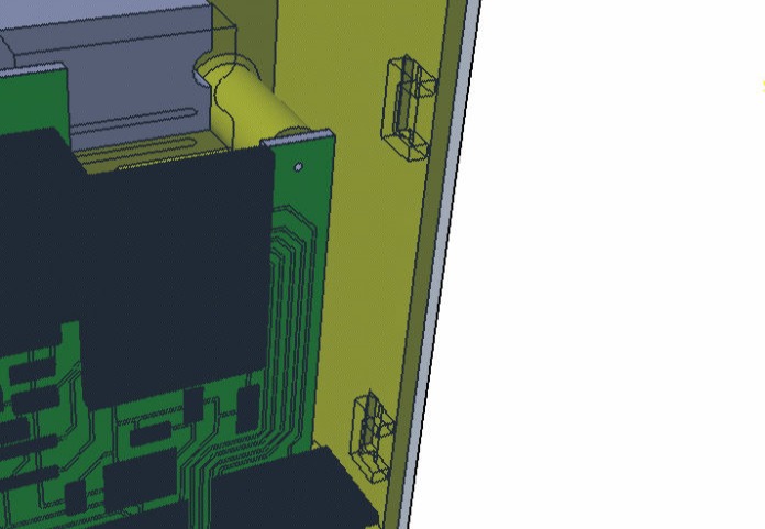
After the Design and export for electronics design was done, parallely, 3D modeification is done where boss and other shapes are added to secure the location of the board, from PCB milling process, it is shown in fabrication process below.
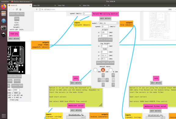
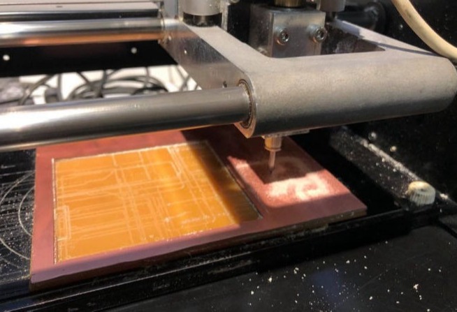
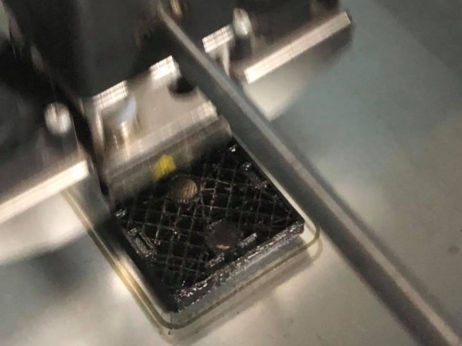
Since the mechanical design was already tested, I wanted to confirm the electronics part first so I did milling first. The png file for the traces, holes and trim line after exported it cut on the copper board with the help of Models via mods platform. You can know the details of the process is electronics production from the link here.
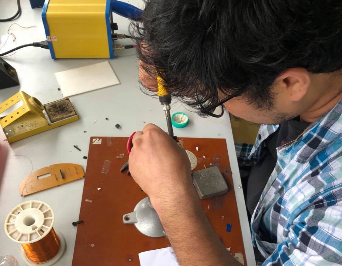
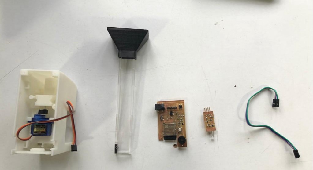
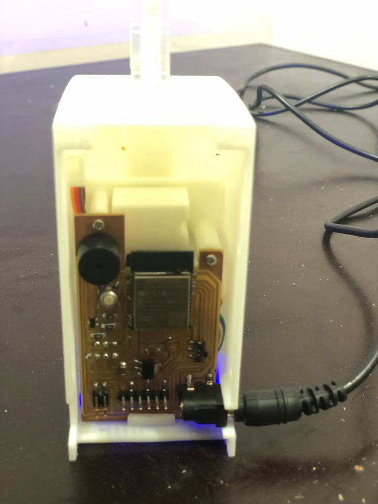
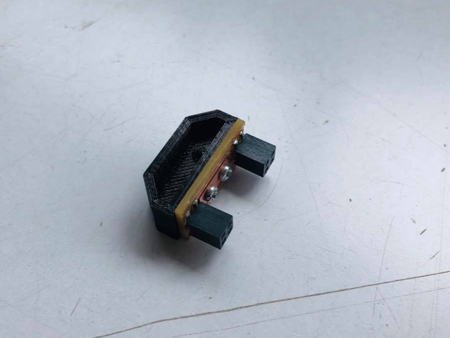
After all the parts are milled, components as listed above were collected from the inventory and stuffed into each board and the master and secondary boards with hall module looks line below.
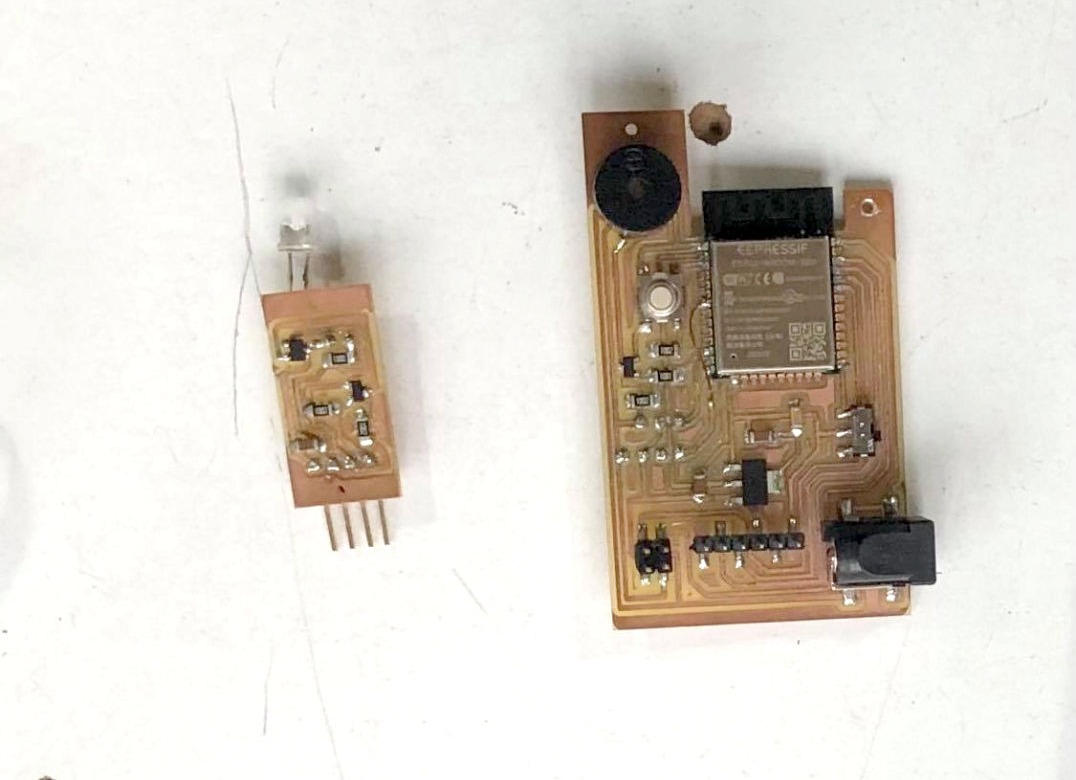
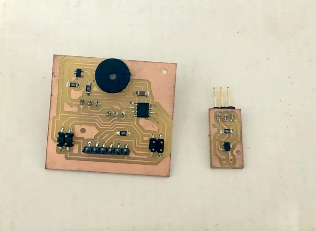
Here you can see jumper wires on the the Main master board which will be explained in the programming and debugging section.
Programming, Debugging and testing
It started with understanding ESP32 first. Here, first the datasheet of ESP32 was studied earlier while deciding [igs. Noe since all parts are there, I started with Node MCU first which I had used during testing the mechanism. So step by step I used program each component.
First connecting to WiFi.
#include <WiFi.h>
const char* ssid = "iPhone"; //WiFi Name
const char* password = "NMF123!!!"; // WiFi Password
void setup()
{
Serial.printf("Connecting to %s ", ssid);
WiFi.begin(ssid, password);
while (WiFi.status() != WL_CONNECTED) {
delay(500);
Serial.print(".");
}
Serial.println(" CONNECTED");
}
void loop()
{
delay(500);
}
Now getting time from the NTP server. Here i have tried to convert everything to seconds so that i can compare only actual seconds to the seconds set by the user to dispense the tables.
#include <WiFi.h>
#include <SPI.h>
#include <NTPClient.h>
#include <WiFiUdp.h>
const char* ssid = "iPhone"; //WiFi Name
const char* password = "NMF123!!!"; // WiFi Password
WiFiUDP ntpUDP;
NTPClient timeClient(ntpUDP, "1.asia.pool.ntp.org", 19800);
void setup()
{
Serial.printf("Connecting to %s ", ssid);
WiFi.begin(ssid, password);
while (WiFi.status() != WL_CONNECTED) {
delay(500);
Serial.print(".");
}
Serial.println(" CONNECTED");
}
void loop()
{
timeClient.update();
int h = timeClient.getHours();
int m = timeClient.getMinutes();
int s = timeClient.getSeconds();
int actsec = h * 3600 + m * 60 + s;
Serial.print(h);
Serial.print(":");
Serial.println(m);
Serial.println(actsec);
delay(500);
}
Now time to connect output device. First i took servo as this was the first thing needed to test the mechanism. Here the servo pin is connected to pin 14 on the board. I kept the servo in a function as it will be easy moving on the project.
#include <SPI.h>
#include <NTPClient.h>
#include <WiFiUdp.h>
#include <Servo_ESP32.h>
#define servoPin 14 //printed G14 on the board
Servo_ESP32 servo1;
int angle = 0;
int angleMin = 0;
int angleMax = 180;
int angleStep = 1;
int med_qty = 0;
const char* ssid = "iPhone"; //WiFi Name
const char* password = "NMF123!!!"; // WiFi Password
WiFiUDP ntpUDP;
NTPClient timeClient(ntpUDP, "1.asia.pool.ntp.org", 19800);
void setup()
{
Serial.begin(115200);
servo1.attach(servoPin);
//connect to WiFi
Serial.printf("Connecting to %s ", ssid);
WiFi.begin(ssid, password);
while (WiFi.status() != WL_CONNECTED) {
delay(500);
Serial.print(".");
}
Serial.println(" CONNECTED");
}
void loop()
{
timeClient.update();
int h = timeClient.getHours();
int m = timeClient.getMinutes();
int s = timeClient.getSeconds();
int actsec = h * 3600 + m * 60 + s;
Serial.print(h);
Serial.print(":");
Serial.println(m);
Serial.println(actsec);
dispense(10);
delay(500);
}
void dispense(int med_qty) {
for (int i = 1 ; i <= med_qty; i++) {
for (int angle = angleMin; angle <= angleMax; angle += angleStep) {
servo1.write(angle);
Serial.println(angle);
delay(20);
}
delay(100);
for (int angle = angleMax; angle >= angleMin; angle -= angleStep) {
servo1.write(angle);
Serial.println(angle);
delay(20);
}
delay(100);
}
}
Now the servo was tested and tuned to the required angle for smooth operation where the minimum angle came out to be 100 and maximum 170. Then time to test hall sensor and buzzer. For the hall sensor, I have to know the range or characterstics of the hall sensor, Hence first it was tested, but the value I had received was so unreliable. Sometimes it was jumping up and sometimes down even where there was no magnet. I tried just hall sensor only but was working fine. I was using analog read as i wanted to set alarm according to distance of magnet. Using hall sensor only I found the spot for me, i.e if the value is less than or equal to 3500 set the alarm or set it off. However, When i tried to combine it with other part of code, it does not work.
void setup()
{
pinMode(hall, INPUT);
}
void loop()
{
Serial.println(analogRead(hall));
delay(500);
}
I spend whole day just for finding out what is wrong. I tried digital read. I tried deleting and adding each part of program and finally found out that the pin that is connecting to hall sensor does not work when ESP32 is connected to WiFi. May be it is the problem with the inbuilt library but according to the forum and answers of people, ADC2 does not work for hall sensor when it is connected to WiFi. Only pins GPIO 34, 35, 36, and 39 can be used for analog reading. Here is the link to the forum. Then I disconnected the connection from the pin 12 and used jumper wire to connect that trace to pin. and uploaded all the code with Wifi anf finally it was working fine. Then for buzzer, I wanted to just have a strobe kind meaning just on off in a delay as it is an alarm to have tablets. Here buzzer is connected to Pin 27 and hall in Pin 35 (via jumper wire).
#include <SPI.h>
#include <NTPClient.h>
#include <WiFiUdp.h>
#include <Servo_ESP32.h>
#define servoPin 14 //printed G14 on the board
#define buzzer 27
#define hall 35
Servo_ESP32 servo1;
int angle = 100;
int angleMin = 100;
int angleMax = 170;
int angleStep = 1;
int med_qty = 0;
const char* ssid = "iPhone"; //WiFi Name
const char* password = "NMF123!!!"; // WiFi Password
WiFiUDP ntpUDP;
NTPClient timeClient(ntpUDP, "1.asia.pool.ntp.org", 19800);
void setup()
{
Serial.begin(115200);
servo1.attach(servoPin);
pinMode(buzzer, OUTPUT);
pinMode(hall, INPUT);
//connect to WiFi
Serial.printf("Connecting to %s ", ssid);
WiFi.begin(ssid, password);
while (WiFi.status() != WL_CONNECTED) {
delay(500);
Serial.print(".");
}
Serial.println(" CONNECTED");
}
void loop()
{
timeClient.update();
int h = timeClient.getHours();
int m = timeClient.getMinutes();
int s = timeClient.getSeconds();
int actsec = h * 3600 + m * 60 + s;
Serial.print(h);
Serial.print(":");
Serial.println(m);
dispense(med_qty);
while (analogRead(hall) <= 3500) {
buzz();
}
delay(500);
}
void dispense(int med_qty) {
for (int i = 1 ; i <= med_qty; i++) {
for (int angle = angleMin; angle <= angleMax; angle += angleStep) {
servo1.write(angle);
Serial.println(angle);
delay(20);
}
delay(100);
for (int angle = angleMax; angle >= angleMin; angle -= angleStep) {
servo1.write(angle);
Serial.println(angle);
delay(20);
}
delay(100);
}
}
void buzz() {
digitalWrite(buzzer, 1);
delay(100);
digitalWrite(buzzer, 0);
delay(100);
}
User Interface
In first cycle, I am using Blynk application for setting time, quantity and model number for the secondary as well.. As this application is easy to use and have been used in other IOT devices, I decide to use it for the first phase and during the futher development of the product, dedicated application can be made from platforms like AppInventor, Thunkable, etc. There is a simiilar platform that is offered by arduino as well which you can try from this link.

Blynk IoT platform offers a full suite of software allowing to prototype, deploy, and remotely manage connected electronic devices at any scale: from small IoT projects to millions of commercial connected products. With Blynk, you can connect hardware to the cloud and use pre-made app modules to build iOS, Android, and web applications ready for the end-users. In short, Blynk is an “Internet of Things” (IoT) platform that allows you to build your own apps to control certain devices over the internet.
Steps for using Blynk
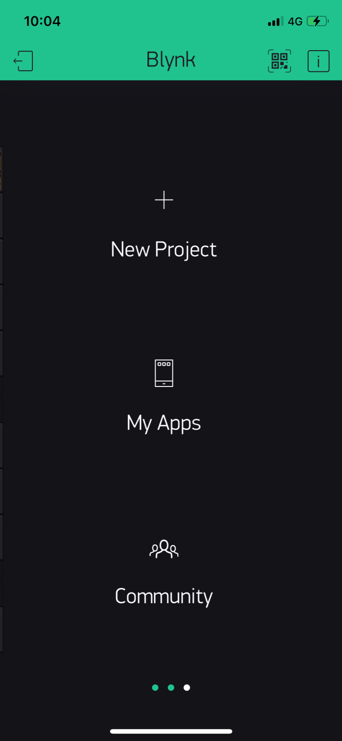
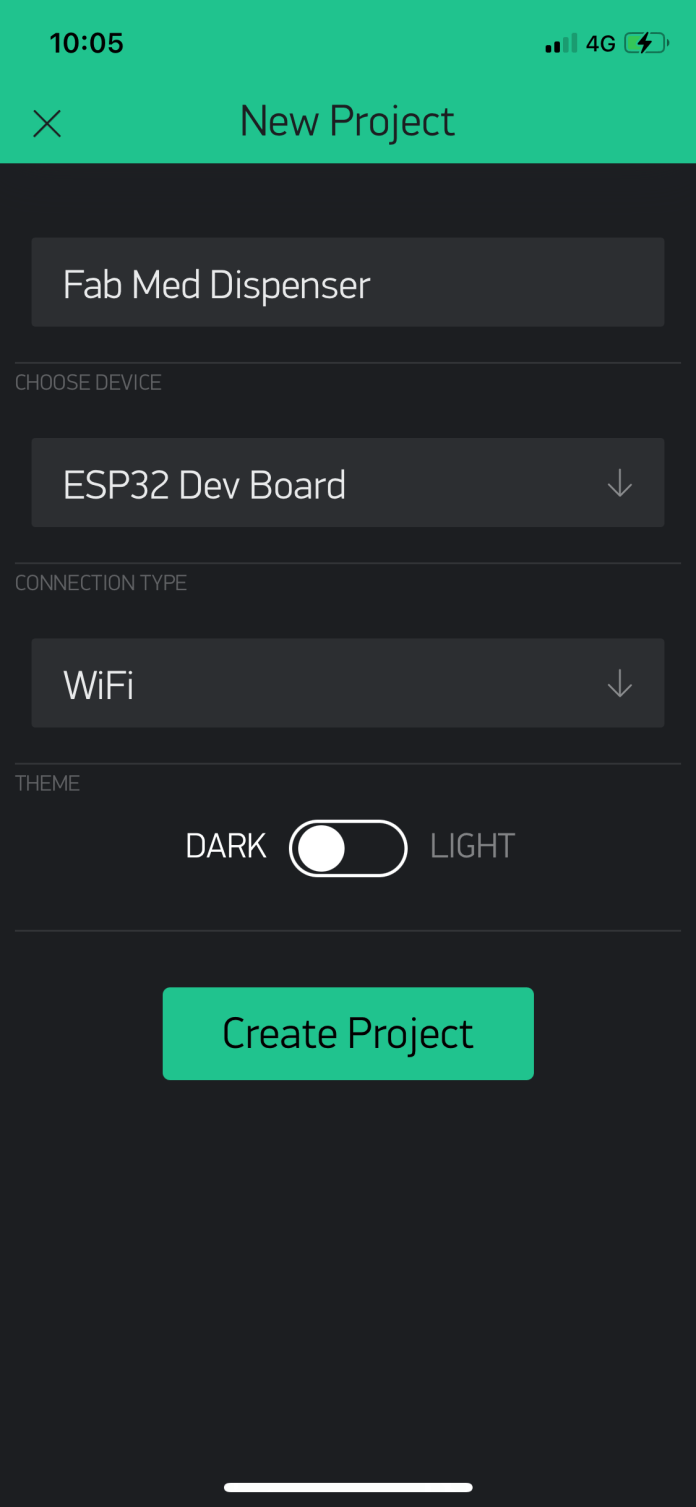
It is very easy to use Blynk. First you have to download the application from app store if you are an iPhone user of google play if you are using android. I am using iPhone so will be giving example on that one. After you download the application see the step below how I created the application
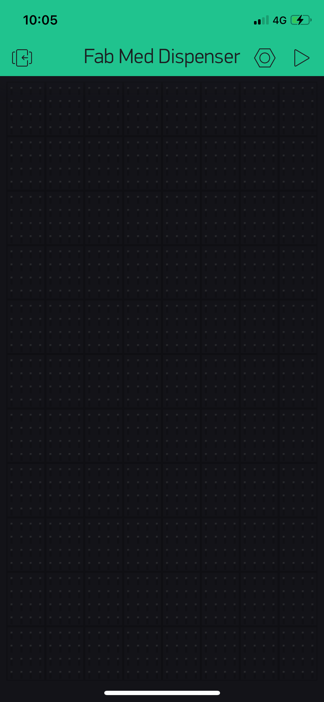
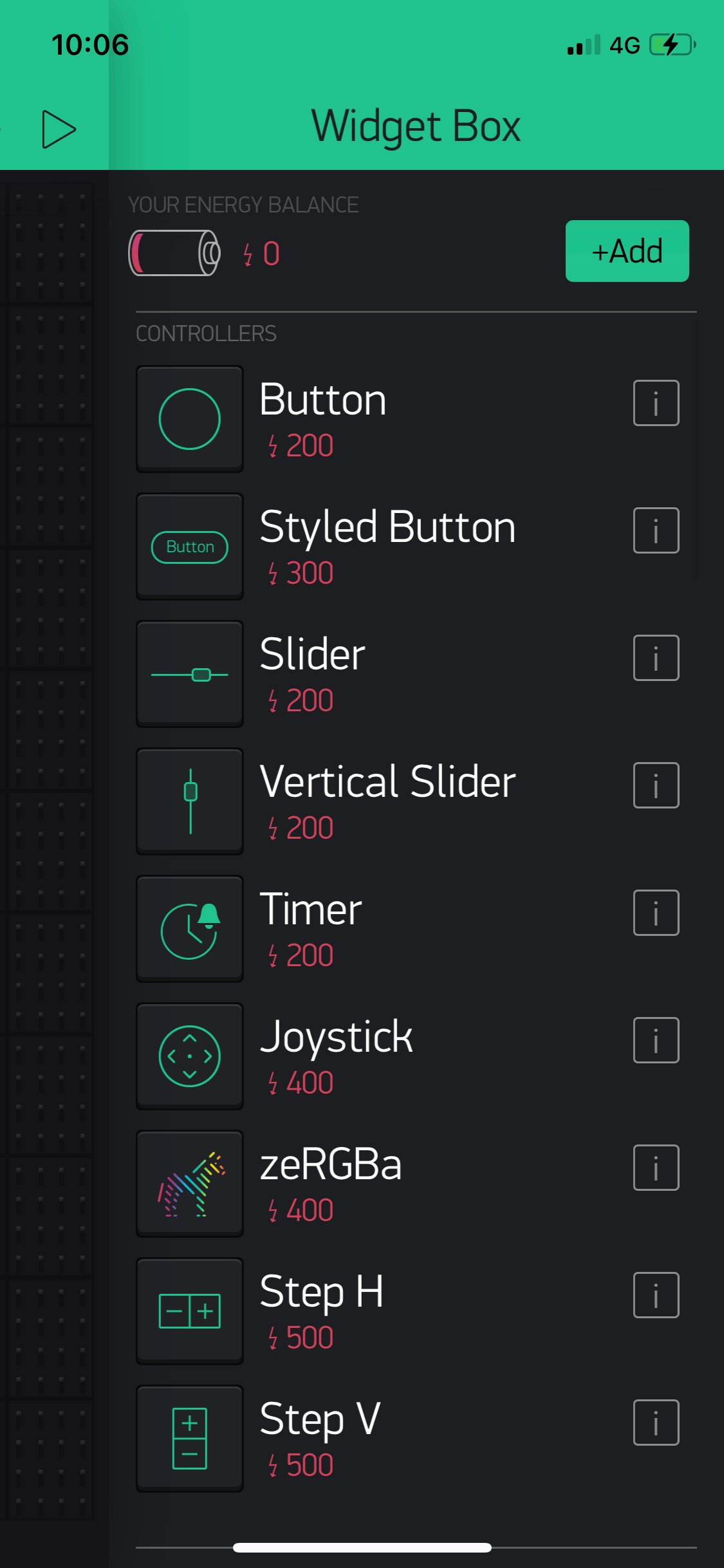
After arranging different widgets here and there you will get to the layout suitable for you. For me the layout shown below was the required one.
Linking Programming and GUI pins
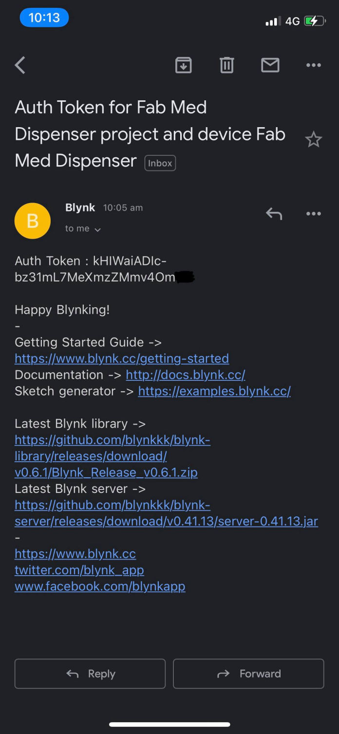
First the main program is opened and install the blynk library which you can download from this link. Then ass the library on your Arduino IDE. you can also get different example using this link where you can select between your boards as well as programs from this link. Now after everything is set on the mobile, get your authentication code and note the virtual pin that you have selected. Then the code from the previous step was edited to test blynk.
#include <SPI.h>
#include <NTPClient.h>
#include <WiFiUdp.h>
#include <Servo_ESP32.h>
#include <BlynkSimpleEsp32.h>
#include "time.h"
#define servoPin 14 //printed G14 on the board
#define buzzer 27
#define hall 35
Servo_ESP32 servo1;
int angle = 100;
int angleMin = 100;
int angleMax = 170;
int angleStep = 1;
int med_qty = 0;
int buttonState = 0;
int setsec1 = 0;
int setsec2 = 0;
int setsec3 = 0;
char auth[] = "CXPXe4FBMq3APKm3-9C0hI5wrK1lKW5x";
const char* ssid = "iPhone"; //WiFi Name
const char* password = "NMF123!!!"; // WiFi Password
WiFiUDP ntpUDP;
NTPClient timeClient(ntpUDP, "1.asia.pool.ntp.org", 19800);
void setup()
{
Serial.begin(115200);
Blynk.begin(auth, ssid, password);
servo1.attach(servoPin);
pinMode(buzzer, OUTPUT);
pinMode(hall, INPUT);
//connect to WiFi
Serial.printf("Connecting to %s ", ssid);
WiFi.begin(ssid, password);
while (WiFi.status() != WL_CONNECTED) {
delay(500);
Serial.print(".");
}
Serial.println(" CONNECTED");
}
void loop()
{
timeClient.update();
int h = timeClient.getHours();
int m = timeClient.getMinutes();
int s = timeClient.getSeconds();
int actsec = h * 3600 + m * 60 + s;
Serial.print(h);
Serial.print(":");
Serial.println(m);
Blynk.run();
if (actsec == setsec1 || actsec == setsec2 || actsec == setsec3 || buttonState == 1) {
dispense(med_qty);
while (analogRead(hall) <= 3500) {
buzz();
}
}
delay(500);
}
void dispense(int med_qty) {
for (int i = 1 ; i <= med_qty; i++) {
for (int angle = angleMin; angle <= angleMax; angle += angleStep) {
servo1.write(angle);
Serial.println(angle);
delay(20);
}
delay(100);
for (int angle = angleMax; angle >= angleMin; angle -= angleStep) {
servo1.write(angle);
Serial.println(angle);
delay(20);
}
delay(100);
}
}
void buzz() {
digitalWrite(buzzer, 1);
delay(100);
digitalWrite(buzzer, 0);
delay(100);
}
BLYNK_WRITE(V0)
{
med_qty = param.asInt(); // assigning incoming value from pin V1 to a variable
}
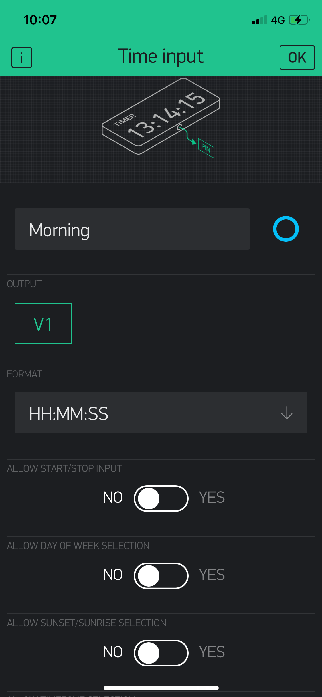
BLYNK_WRITE(V1) {
TimeInputParam t(param);
if (t.hasStartTime())
{
Serial.println(String("Start: ") +
t.getStartHour() + ":" +
t.getStartMinute() + ":" +
t.getStartSecond());
setsec1 = (t.getStartHour() * 3600) + (t.getStartMinute() * 60) + t.getStartSecond();
}
}
BLYNK_WRITE(V2) {
TimeInputParam t(param);
if (t.hasStartTime())
{
Serial.println(String("Start: ") +
t.getStartHour() + ":" +
t.getStartMinute() + ":" +
t.getStartSecond());
setsec2 = (t.getStartHour() * 3600) + (t.getStartMinute() * 60) + t.getStartSecond();
}
}
BLYNK_WRITE(V3) {
TimeInputParam t(param);
if (t.hasStartTime())
{
Serial.println(String("Start: ") +
t.getStartHour() + ":" +
t.getStartMinute() + ":" +
t.getStartSecond());
setsec3 = (t.getStartHour() * 3600) + (t.getStartMinute() * 60) + t.getStartSecond();
}
}
BLYNK_WRITE(V4)
{
buttonState = param.asInt(); // assigning incoming value from pin V1 to a variable
}
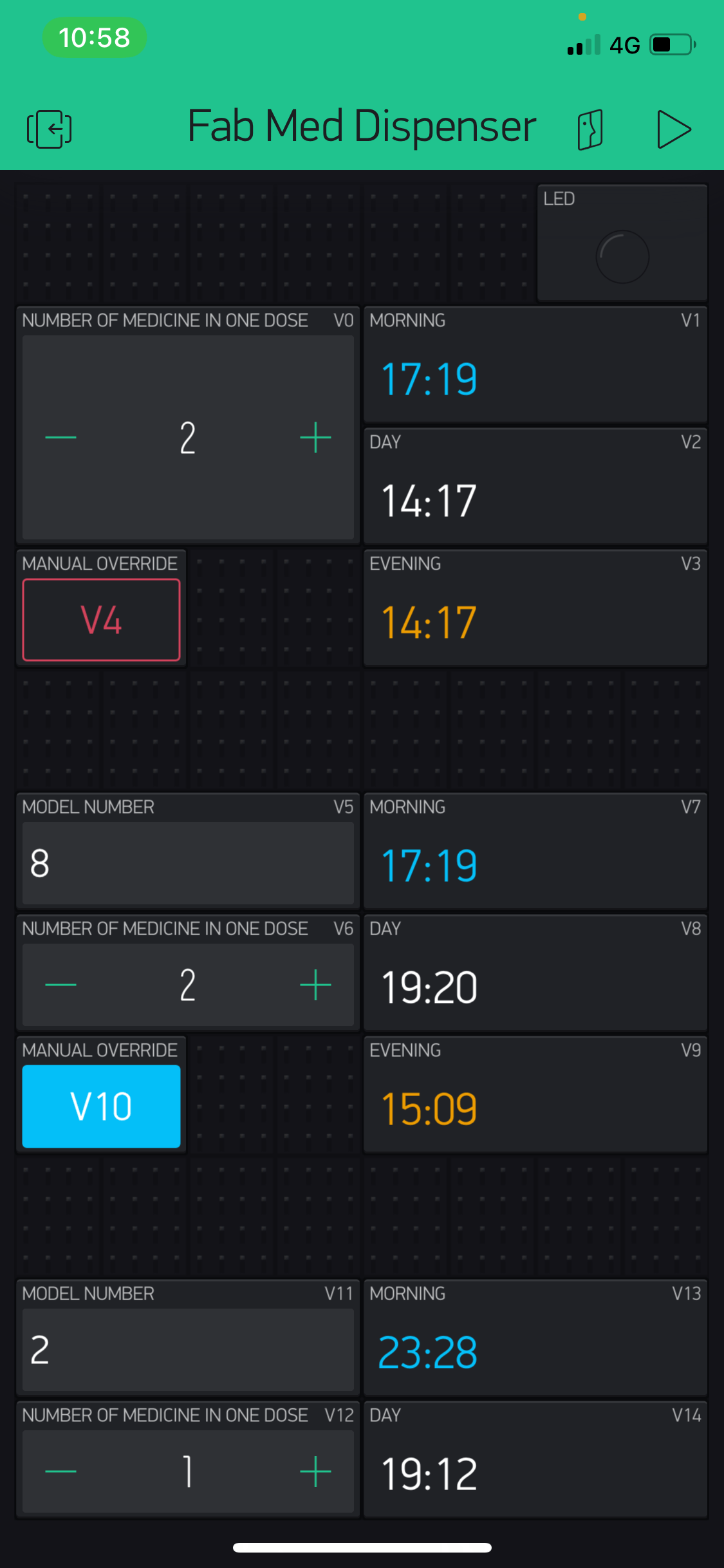
Here you can see the virtual pins being used under BLYNK_WRITE(V0) and similarly for other pins and the program was working for all the pins as set on the application.
Then I added the i2c connection where address "8" was given to the secondary boards and then the code was added and here from the GUI i programmed that the address should also be inserted by the user according to the module they buy. Hence following is the final code that I made for the main board or master board.
#include <SPI.h>
#include <NTPClient.h>
#include <WiFiUdp.h>
#include <Servo_ESP32.h>
#include <BlynkSimpleEsp32.h>
#include <Wire.h>
#include "time.h"
#define servoPin 14 //printed G14 on the board
#define buzzer 27
#define hall 35
Servo_ESP32 servo1;
int angle = 100;
int angleMin = 100;
int angleMax = 170;
int angleStep = 1;
int med_qty = 0;
int buttonState = 0;
int setsec1 = 0;
int setsec2 = 0;
int setsec3 = 0;
int med_qty_sl1 = 0;
int buttonState_sl1 = 0;
int model1 = 0;
int setsec4 = 0;
int setsec5 = 0;
int setsec6 = 0;
int med_qty_sl2 = 0;
int buttonState_sl2 = 0;
int model2 = 0;
int setsec7 = 0;
int setsec8 = 0;
int setsec9 = 0;
char auth[] = "CXPXe4FBMq3APKm3-9C0hI5wrK1lKW5x";
const char* ssid = "iPhone"; //WiFi Name
const char* password = "NMF123!!!"; // WiFi Password
WiFiUDP ntpUDP;
NTPClient timeClient(ntpUDP, "1.asia.pool.ntp.org", 19800);
void setup()
{
Serial.begin(115200);
Blynk.begin(auth, ssid, password);
servo1.attach(servoPin);
pinMode(buzzer, OUTPUT);
pinMode(hall, INPUT);
//connect to WiFi
Serial.printf("Connecting to %s ", ssid);
WiFi.begin(ssid, password);
while (WiFi.status() != WL_CONNECTED) {
delay(500);
Serial.print(".");
}
Serial.println(" CONNECTED");
Wire.begin();
}
void loop()
{
timeClient.update();
int h = timeClient.getHours();
int m = timeClient.getMinutes();
int s = timeClient.getSeconds();
int actsec = h * 3600 + m * 60 + s;
Serial.print(h);
Serial.print(":");
Serial.println(m);
Blynk.run();
Serial.println(setsec1);
if (actsec == setsec4 || actsec == setsec5 || actsec == setsec6 || buttonState_sl1 == 1) {
Wire.beginTransmission(model1);
Wire.write(med_qty_sl1);
Wire.endTransmission();
}
if (actsec == setsec7 || actsec == setsec8 || actsec == setsec9 || buttonState_sl2 == 1) {
Wire.beginTransmission(model2);
Wire.write(med_qty_sl2);
Wire.endTransmission();
}
if (actsec == setsec1 || actsec == setsec2 || actsec == setsec3 || buttonState == 1) {
dispense(med_qty);
while (analogRead(hall) <= 3500) {
buzz();
}
}
delay(500);
}
void dispense(int med_qty) {
for (int i = 1 ; i <= med_qty; i++) {
for (int angle = angleMin; angle <= angleMax; angle += angleStep) {
servo1.write(angle);
Serial.println(angle);
delay(20);
}
delay(100);
for (int angle = angleMax; angle >= angleMin; angle -= angleStep) {
servo1.write(angle);
Serial.println(angle);
delay(20);
}
delay(100);
}
}
void buzz() {
digitalWrite(buzzer, 1);
delay(100);
digitalWrite(buzzer, 0);
delay(100);
}
BLYNK_WRITE(V0)
{
med_qty = param.asInt(); // assigning incoming value from pin V1 to a variable
}
BLYNK_WRITE(V1) {
TimeInputParam t(param);
if (t.hasStartTime())
{
Serial.println(String("Start: ") +
t.getStartHour() + ":" +
t.getStartMinute() + ":" +
t.getStartSecond());
setsec1 = (t.getStartHour() * 3600) + (t.getStartMinute() * 60) + t.getStartSecond();
}
}
BLYNK_WRITE(V2) {
TimeInputParam t(param);
if (t.hasStartTime())
{
Serial.println(String("Start: ") +
t.getStartHour() + ":" +
t.getStartMinute() + ":" +
t.getStartSecond());
setsec2 = (t.getStartHour() * 3600) + (t.getStartMinute() * 60) + t.getStartSecond();
}
}
BLYNK_WRITE(V3) {
TimeInputParam t(param);
if (t.hasStartTime())
{
Serial.println(String("Start: ") +
t.getStartHour() + ":" +
t.getStartMinute() + ":" +
t.getStartSecond());
setsec3 = (t.getStartHour() * 3600) + (t.getStartMinute() * 60) + t.getStartSecond();
}
}
BLYNK_WRITE(V4)
{
buttonState = param.asInt(); // assigning incoming value from pin V1 to a variable
}
BLYNK_WRITE(V5)
{
model1 = param.asInt(); // assigning incoming value from pin V1 to a variable
}
BLYNK_WRITE(V6)
{
med_qty_sl1 = param.asInt(); // assigning incoming value from pin V1 to a variable
}
BLYNK_WRITE(V7) {
TimeInputParam t(param);
if (t.hasStartTime())
{
Serial.println(String("Start: ") +
t.getStartHour() + ":" +
t.getStartMinute() + ":" +
t.getStartSecond());
setsec4 = (t.getStartHour() * 3600) + (t.getStartMinute() * 60) + t.getStartSecond();
}
}
BLYNK_WRITE(V8) {
TimeInputParam t(param);
if (t.hasStartTime())
{
Serial.println(String("Start: ") +
t.getStartHour() + ":" +
t.getStartMinute() + ":" +
t.getStartSecond());
setsec5 = (t.getStartHour() * 3600) + (t.getStartMinute() * 60) + t.getStartSecond();
}
}
BLYNK_WRITE(V9) {
TimeInputParam t(param);
if (t.hasStartTime())
{
Serial.println(String("Start: ") +
t.getStartHour() + ":" +
t.getStartMinute() + ":" +
t.getStartSecond());
setsec6 = (t.getStartHour() * 3600) + (t.getStartMinute() * 60) + t.getStartSecond();
}
}
BLYNK_WRITE(V10)
{
buttonState_sl1 = param.asInt(); // assigning incoming value from pin V1 to a variable
}
BLYNK_WRITE(V11)
{
model2 = param.asInt(); // assigning incoming value from pin V1 to a variable
}
BLYNK_WRITE(V12)
{
med_qty_sl2 = param.asInt(); // assigning incoming value from pin V1 to a variable
}
BLYNK_WRITE(V13) {
TimeInputParam t(param);
if (t.hasStartTime())
{
Serial.println(String("Start: ") +
t.getStartHour() + ":" +
t.getStartMinute() + ":" +
t.getStartSecond());
setsec7 = (t.getStartHour() * 3600) + (t.getStartMinute() * 60) + t.getStartSecond();
}
}
BLYNK_WRITE(V14) {
TimeInputParam t(param);
if (t.hasStartTime())
{
Serial.println(String("Start: ") +
t.getStartHour() + ":" +
t.getStartMinute() + ":" +
t.getStartSecond());
setsec8 = (t.getStartHour() * 3600) + (t.getStartMinute() * 60) + t.getStartSecond();
}
}
BLYNK_WRITE(V15) {
TimeInputParam t(param);
if (t.hasStartTime())
{
Serial.println(String("Start: ") +
t.getStartHour() + ":" +
t.getStartMinute() + ":" +
t.getStartSecond());
setsec9 = (t.getStartHour() * 3600) + (t.getStartMinute() * 60) + t.getStartSecond();
}
}
BLYNK_WRITE(V16)
{
buttonState_sl2 = param.asInt(); // assigning incoming value from pin V1 to a variable
}
For coding secondary the same code will be used for all the secondary board hence produced but the address should be changed according to the sticker that will be pasted on the model which will be cut by vinyl cutter.
Following is the code that will be used.
#include <Servo.h>
#define buzz 4
#define hall 1
Servo myservo;
volatile bool flag = 0;
volatile int val = 0;
int angle = 0;
void setup() {
Wire.begin(8); // please use the address mentioned in the product
Wire.onReceive(receiveEvent);
pinMode(buzz, OUTPUT);
myservo.attach(0);
}
void loop() {
if (flag) {
for (int i = 1; i <= val; i++) {
for (angle = 128; angle <= 180; angle += 1) {
myservo.write(angle);
delay(20);
}
delay(100);
for ( angle = 180; angle >= 128; angle -= 1) {
myservo.write(angle);
delay(20);
}
delay(100);
}
while (analogRead(hall) <= 300) {
digitalWrite(buzz, 1);
delay(100);
digitalWrite(buzz, 0);
delay(100);
}
flag = 0;
}
}
void receiveEvent(int howMany) {
val = Wire.read();
flag = 1;
}
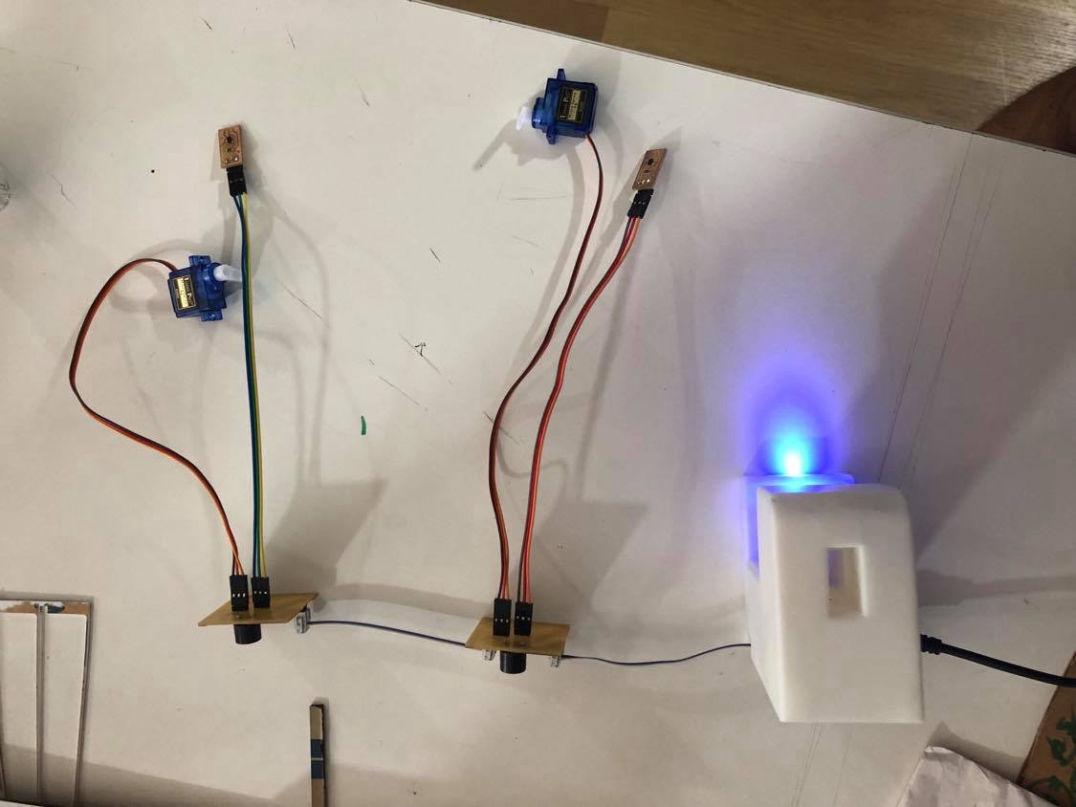
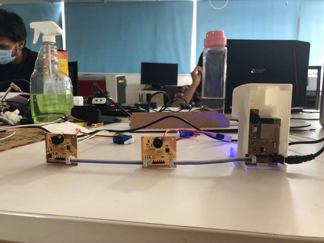
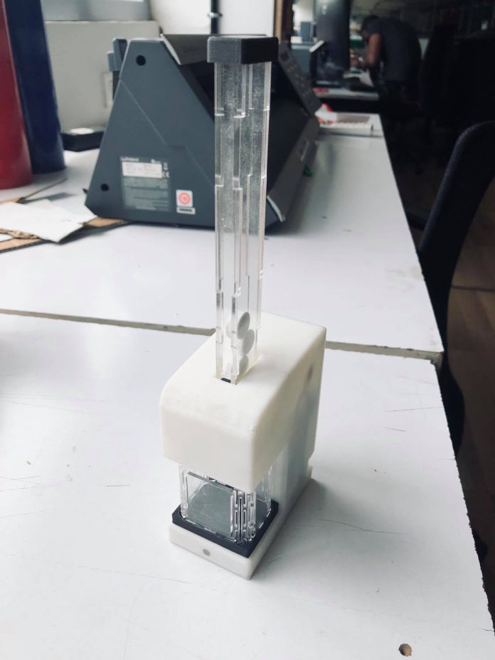
After everything is pushed, and can see the product operating as per expected. The connection and test is shown in the figure below.. Now time to add everything together.
Putting everthing all together
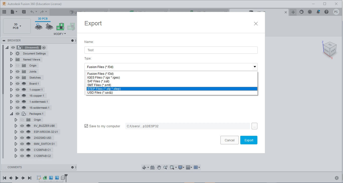
After electronics was designed before fabrication I had to add a way to clamp the board to the casing. As during the electronics design, two hole were made in the feasible area for makin
g the boss, Here I have to get the 3D data of the board which will be easier for making corresponding fitting part in the casing.
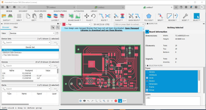
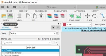
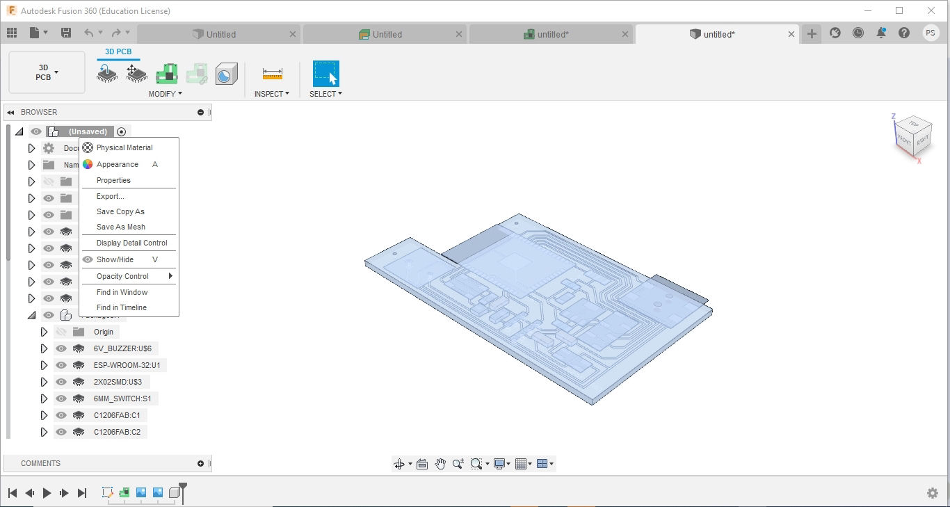
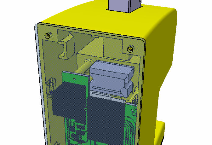
Then, I opened fusion 360 where i went to electronics design and then imported the *.brd file. after the board file is open there might be different errors that you might see due to mismatch of the libraries. However when you click on the 3D PCB in the top left area of the window, you can get a 3D model of your PCB which then can be used to make casing. This is a very handy for making synchronized design and makes it more efficient and easy as well.
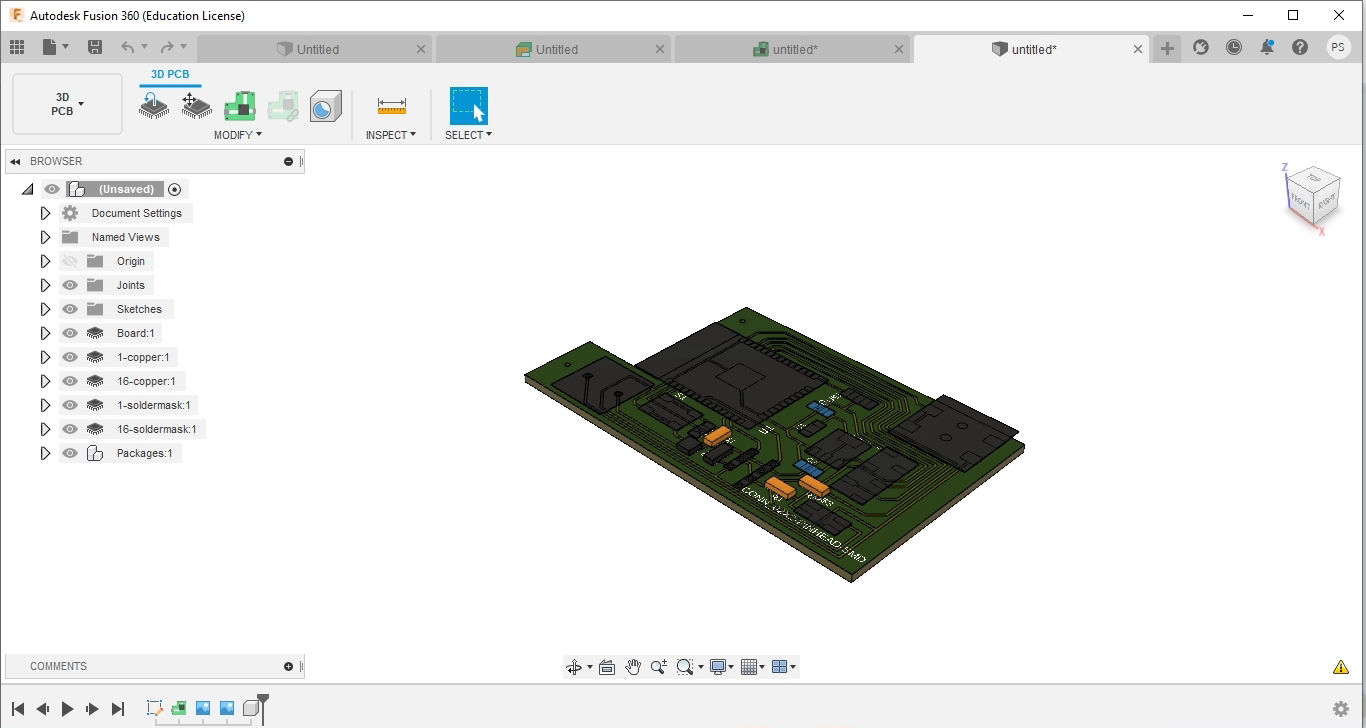
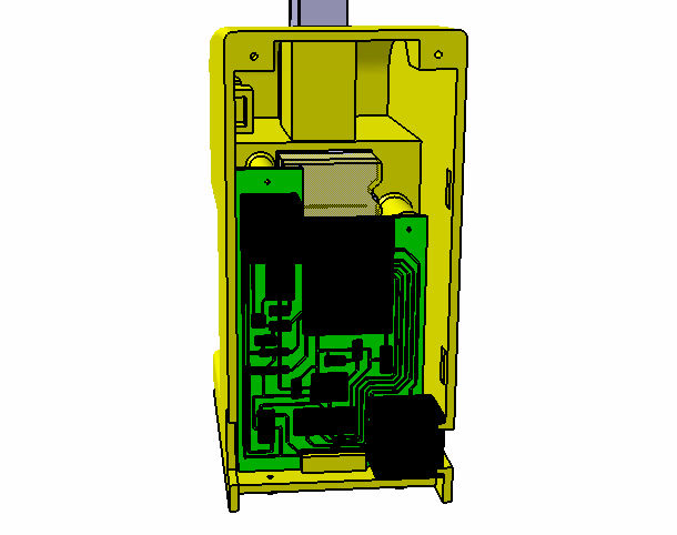
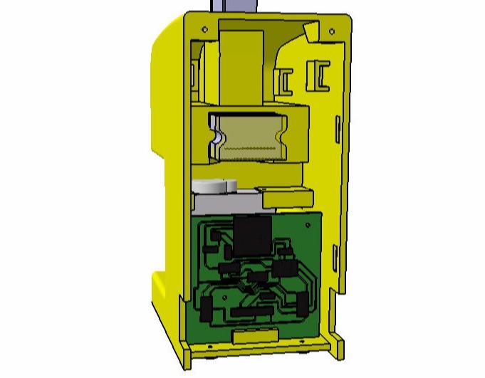
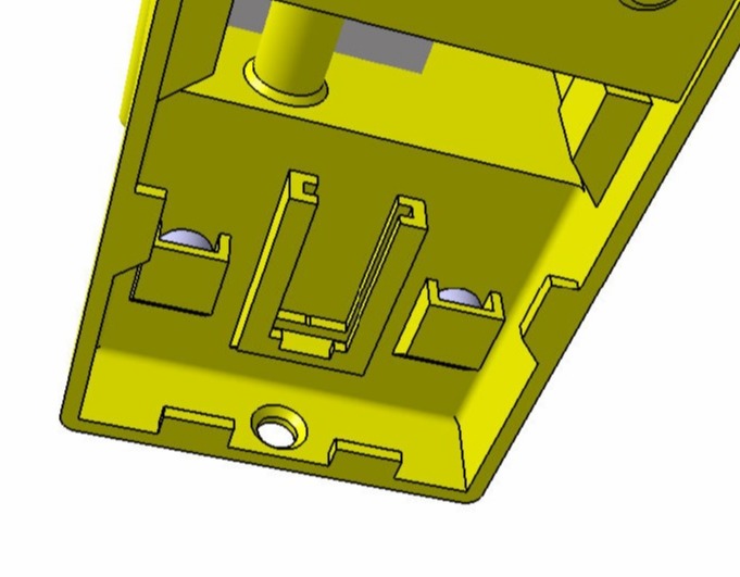
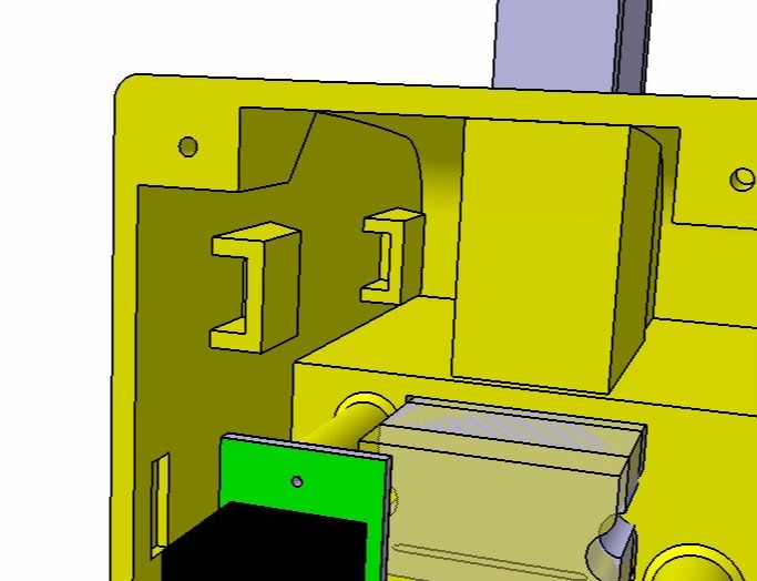
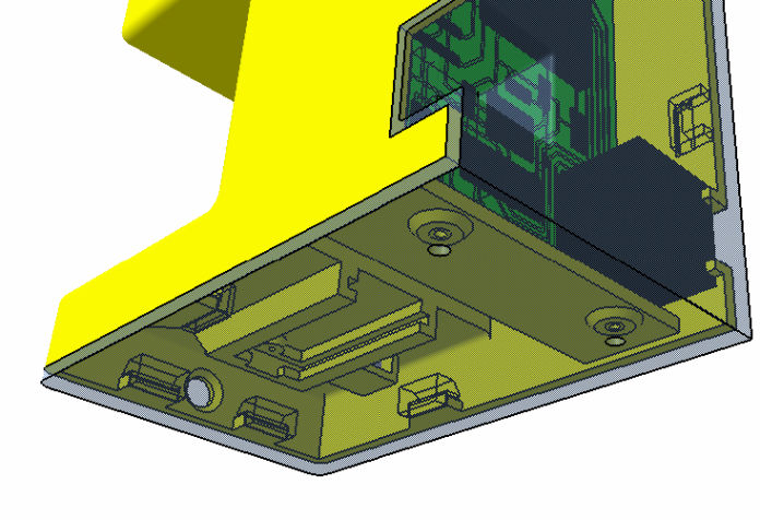
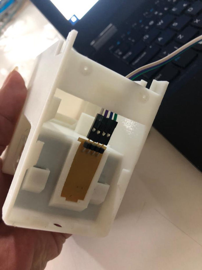
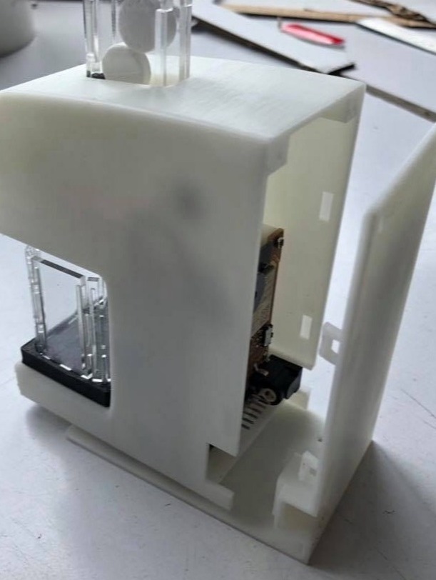
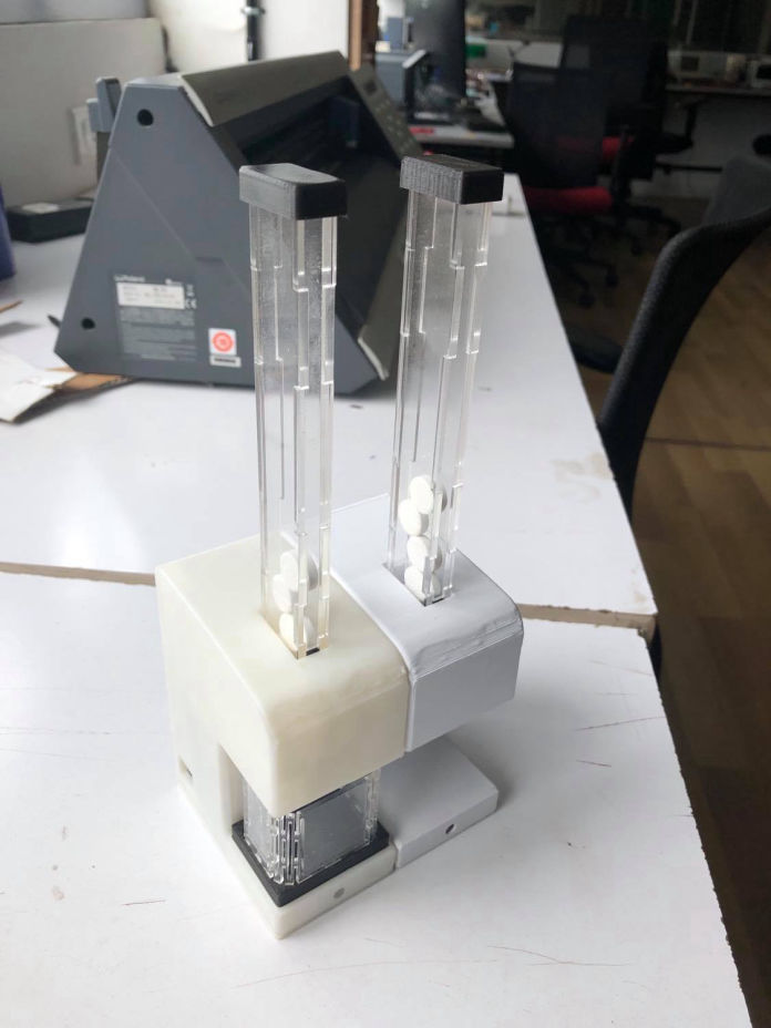
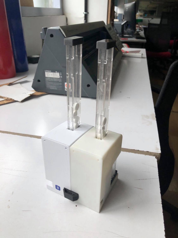
After adding the components, to 3D, boss was added in both master and secondary. the a locking tray is added at the base for the main board. However, for the hall sensor module at bottom, I made a slide type insertion design on the casing. and same for the secondary. Then also added slots for magnets so that it can be used for magnetic tray and for connecting modules
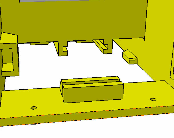
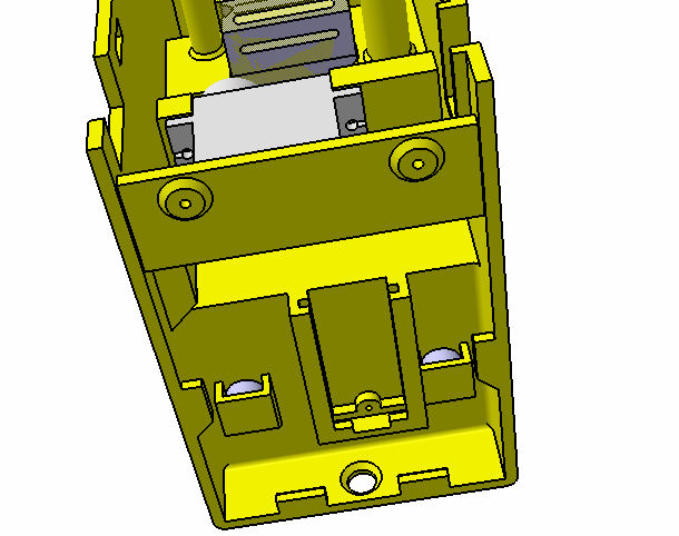
While doing so, i also had to add cover for the whole casing. SO for that I wanted to reduce as much screws as possible so i tried making a slide type lock in the bottom and then 4 screws, two at bottom and two at the top with some snap fit latch in th middle
Fabrication and assembly
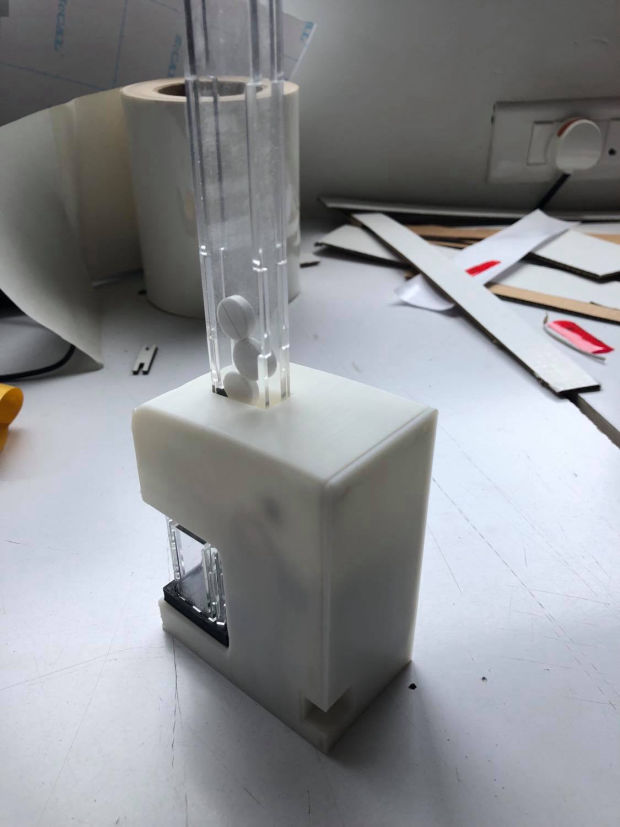
After everything was designed, time for fabrication, the main cartridge is already mage during the design while testing. following are the design files and how it look
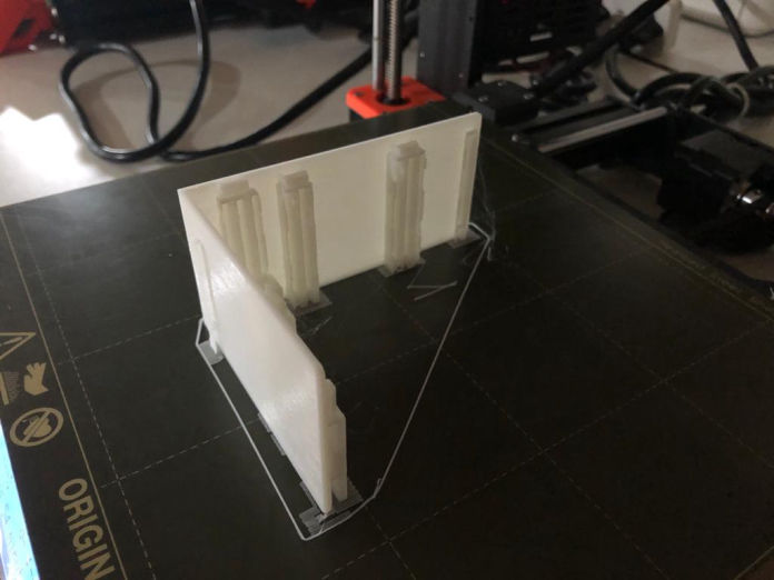
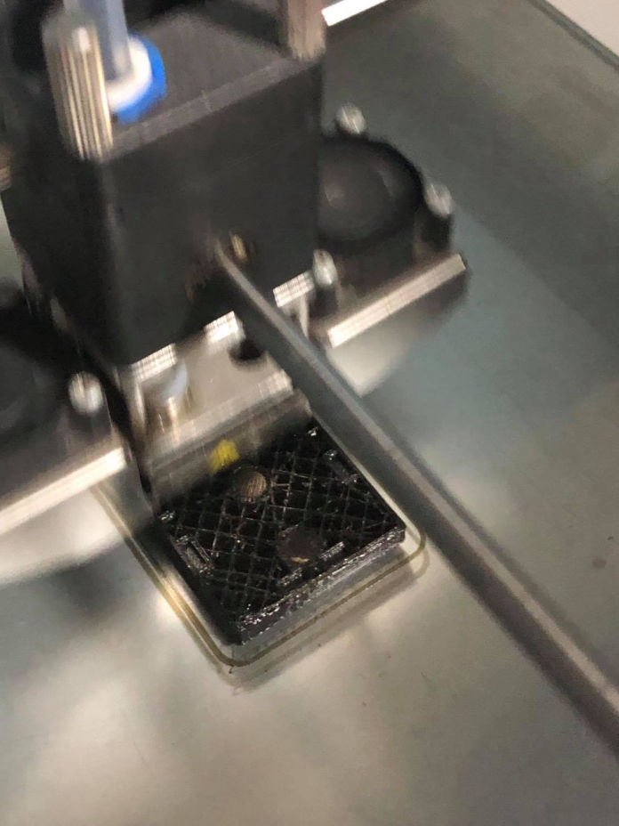
Hopper, hopper lid, cover, casing and the back cover of casing was left for printing in prusa and ultimaker
Adding magnetic tray and making connector
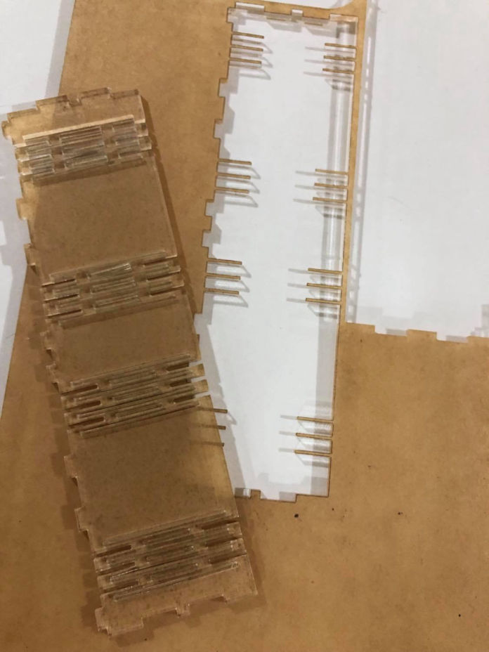
Now for magnetic tray, I wanted to test live hinge from the beginning, So I was trying to incorporate it in my product. Then i Thought of using the transparent laser cut top with magnetic bottom for the tray. Then i tried designing the live hinge, failed couple of time and then finally came up with the design which can just flex and form as per my requirement. the hardest part for me was to find out actual final dimension it would be after bending. But through multiple trials and errors, I was able to cut and assemble in 2mm transparent acrylic.
I also made a connector pins that would go between master and secondary for connecting it by i2c communication.
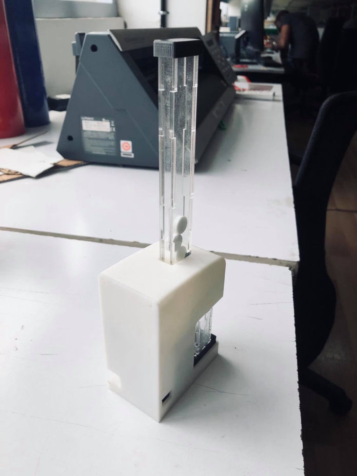
Finally the design
Develop a website with Mobirise