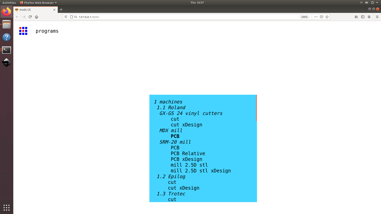
Group
1. Characterize the design rules for your PCB production process
Individual
1. Make an in-circuit programmer that includes a microcontroller by milling and stuffing the PCB
2. Test it, then optionally try other PCB processes
Plan for the week
This week we are focusing on electronics production where we will learn milling, stuffing, de-bugging and programming. In milling we will learn about how to operate the PCB milling machine and cut a circuit board from the machine itself.Personally, I had never done any work on electronics. This is the first time I am fabricating a real circuit board and and stuffing electronics in the board. I am so excited to learn all these skills and use it in the days to come.These week rather on focusing on the design, we will just focus on how to fabricate them and how to stuff electronics in the board with soldering followed by debugging and testing.
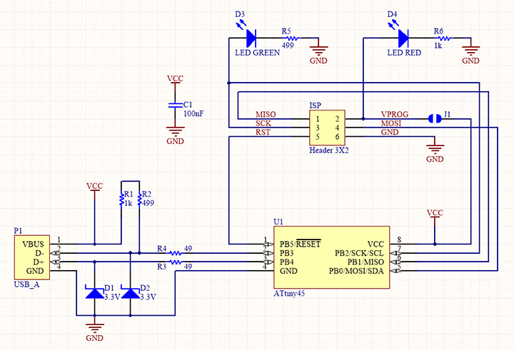
As an individual assignment, I will be making an ISP (In-System Programming) called FabTinyISP. Here I will be using Roland Modela MDX-20 for milling the PCB, learn how to solder and apply it for stuffing the electronics in the board i will be fabricating.
This is a communication device that is used to communicate between the computer and microcontroller. This is used to program the micro-controller.
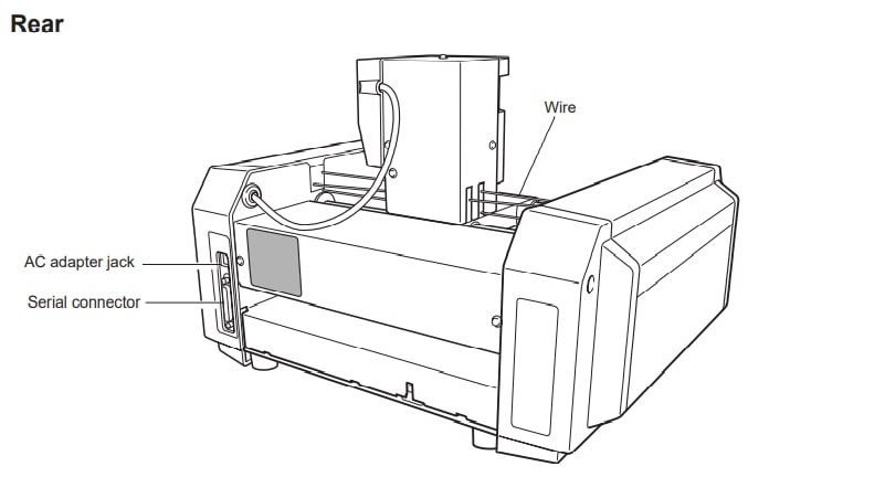
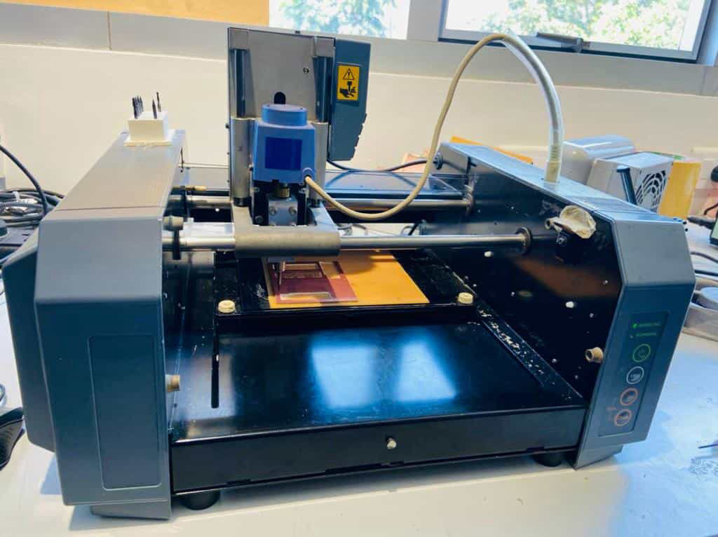
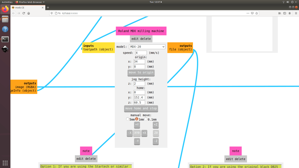
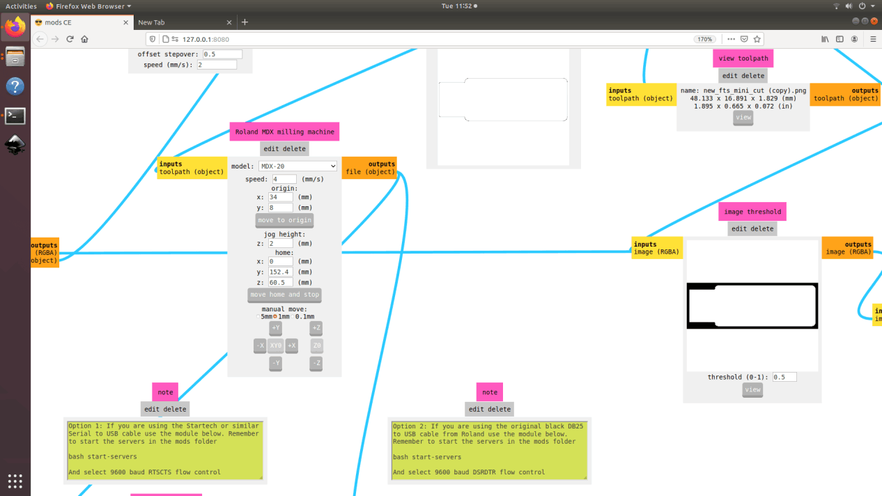
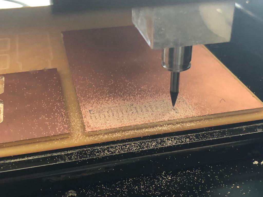
Modela is a very precise CNC mill which can engrave or cut different materials like PCB boards, plastic wax, paper etc. For now, we will be using it for PCB milling to create the ISP. There are four buttons which are on the front right side of the device to control the machine. First one is to turn it on/off, second one is live, which we should turn off to operate cut. then the lower one is up and down which is used to set up Z-axis. Refer to the manual for the detail process about machine, controls and troubleshooting. Rather than focusing on details which is already in the manual , I will try to focus on the operation while cutting the PCB.
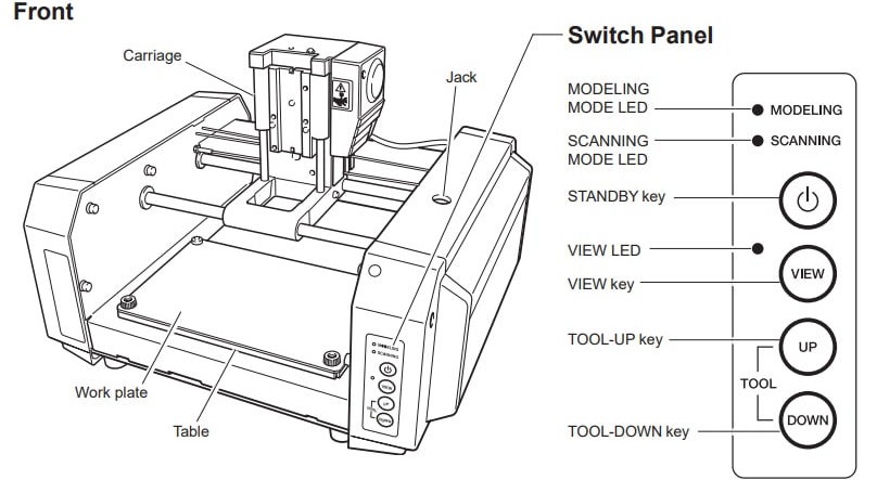
1. Turning on the machine, We have to know how to install the tool and then how to control all three axis.
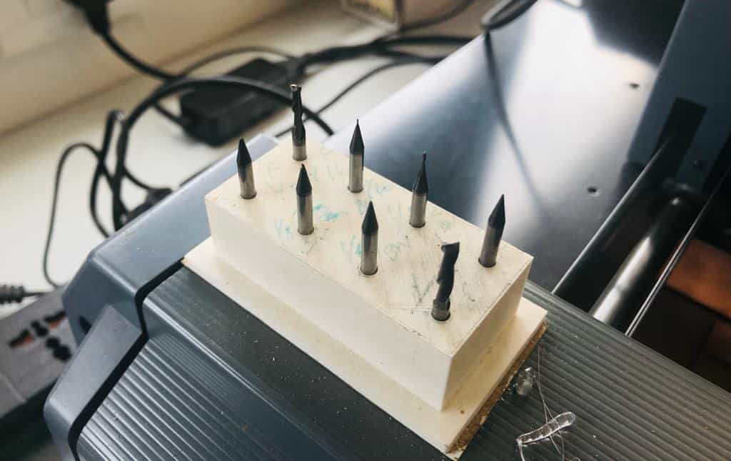
2. Tools that we use are very precise,, thin in diameter and hard as well as brittle due to which we should ensure it does not fall or hit any surface while jogging in any of the axes. The tools that we have in the lab are: 1/64in, 1/32in, V-bits.
3. We have to place the sacrificial layer on to the bed of the machine to ensure the safety of tool as well as to maintain the flat surface of the bed. So place the sacrifical layer on the bed usind double sided tape. Remember do not use the tape with a sponge as it will change its shape while force is applied while milling.
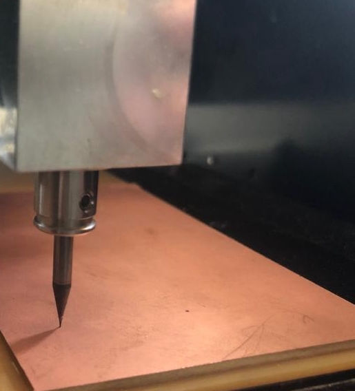
4. For installing or removing the tool, there is 2 screws on each side above the tip of the tool holder. Loosen it if it is tight and hold the tool (end mill 1/16 inch) in your hand in such a way that even if it falls, it should fall on your palm. We should be cautious while installing the tool because the tool tips are very small in diameter such as 1/64 of an inch and if we drop it even from a low height, the tip might break due to its size as well as its brittleness.After pushing in the tool as much as you can push inside, tighten the screw on the either side of about the tip of the tool holder applying torque that is enough to hole the tool. Do not apply very high torque as it might damage the threads on the screws which might in slipping of the screwes resulting loose tool.
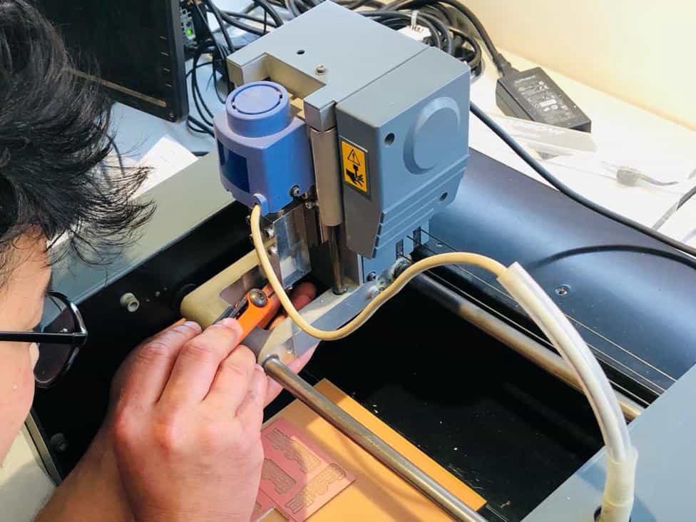
5. Move X and Y axis via mods which i will explain on the process below such that the tool comes above the sacrifical layer. Now adjust the z-axis from the control panel of the machine. Lower it leaving the space of approximately 3-4 mm so that we can perform cut in that range. Loosen the tool by holding the tip of the tool from your fingers, pull it out and slowly place it above the surface we are going to surface mill. This should verify the z-axis to be zero and tighten the screw securing the position of tool.
6. Face mill the top surface of the sacrificial layer so that it becomes parallel to the tool which is very important as we are doing a very precise cutting and also a thin layer of copper, where ant irregularity in the surface my result in different depth of cut resulting poor isolation of the connection lines.
7. Now the machine is ready to be used to cut the PCB.
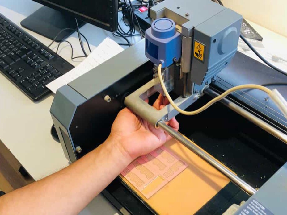
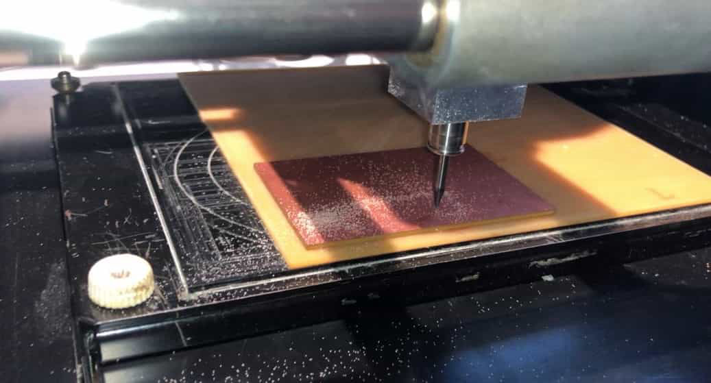
8. Apply double sided tape below the board that is to be cut and place it lower left position squared with the axis.
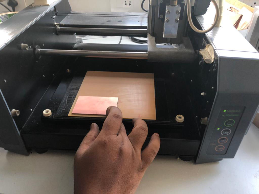
9. Take 1/64 inch tool and place it in the tool holder pushing it to the maximum
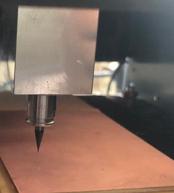
10. Move it to the area above the board so that we can adjust z axis of the tool (movement will be explained in the section below). Then loosen the tool and slowly let it out and place it about the surface you are going to mill and tighten the tool to secure the z-axis.
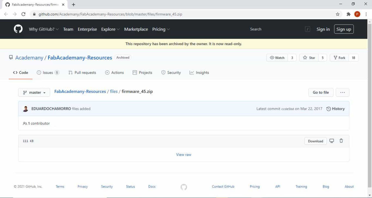
Download files for fabricating FabTiny ISP

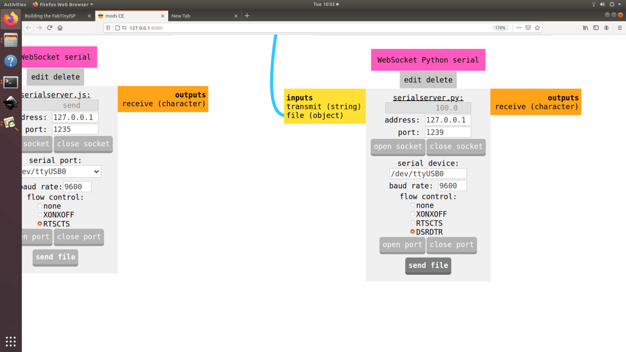
Using Mods to operate the machine
For using Mods please refer the document from Computer-Controlled Cutting to know more about Mods. Though Roland provides the software to operate it while buying the machineMDX-20, we will be using it to mill the board to produe the circuit board. The process is as listed below.
1. Open mods, and click on PCB under MDX mill which should take you to the landing page.
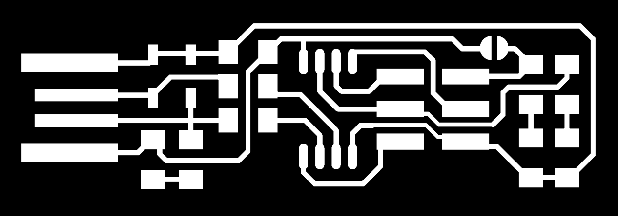
2. Load the png file "fts_mini_traces" you are going to trace from the download earlier.
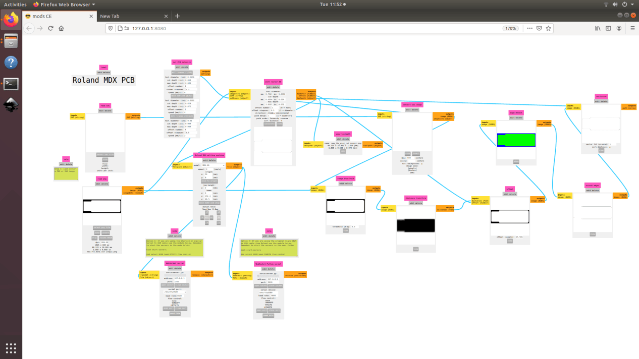
3. Now toggle x and y inside origin to set the datum position of the tool based on which cutting will start. Insert x and y in such a way that it leaves some gap for trimming the board at last. Leave a gp of 3-4 mm for safety. For me, it was 34mm in x and 8mm in y. Z axis should be already in position from previous step. speed is kept at 4mm/s which is standard for a PCB milling. If the speed is very high, it might break the tool and/or have a bad finishing.
4. Now select the tool that you are going to use as a tool. We will be using trace mill of 1/64 inch. Set offset to 4 which means 4 passes offsetting to each pass between the void spaces to maintain the isolation. Set offset stepover to 0.5 which means that during tach pass there will be an operlap of 50% to maintain the smoothness. Set the cut depth to 0.004 inch and same for max depth which shows that there would be one pass only. Hit calculate.
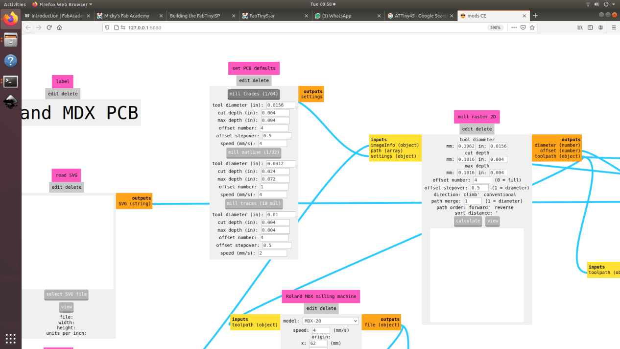
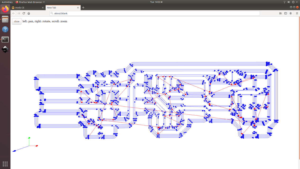
5. Toolpath can be seen as below.
6. For pushing it to the machine, press open socket and then open port and click on send file which should start the milling process.
7. After cutting, you have to trim the board out. This process bust be done after tracing like in most of other manufactruring process. For this, first the tool should be changed to 1/32 inch mill following previous process of tool change and adjust the z axis as done earlier
8. Then on the Mods, load the png file "fts_mini_cut" you are going to cut from the download. earlier. Keeping the x and y same, change the tool to 1/32 inch mill and press calculate and send file shich should start the cut.
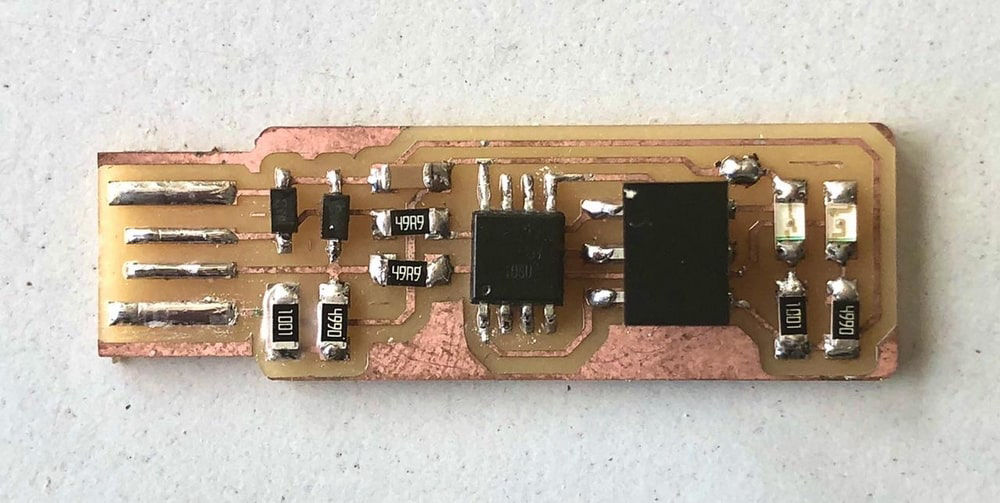
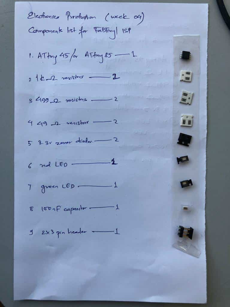
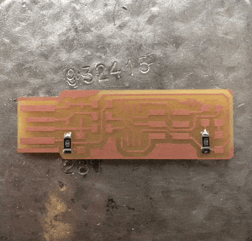
Stuffing the electronics
Now after the milling is done we have to stuff the electronics on to the board. We will be following diagram to stuff them. We will do the surface mount soldering here.
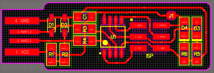
Now stuff them properly on the board with the help of soldering iron. Keep the temperature at 350, keep the tip pointed and keep the flux with you.
Follow this link for knowing how to solder properly.
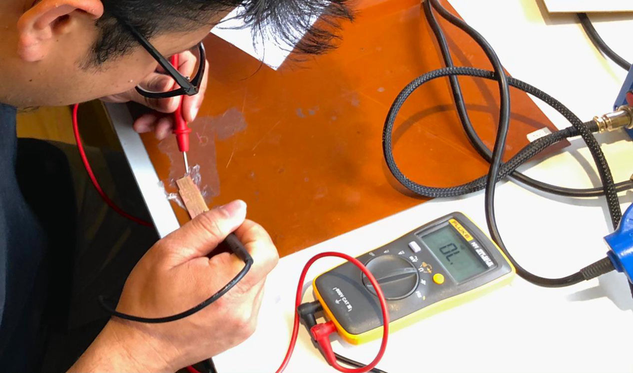
Testing and Programming
Now that the stuffing is done, check the continuity and discontinuity of the board using a multi-meter.
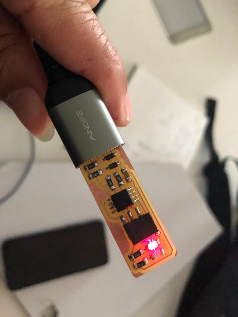
Then connect it to the USB just to check that the red LED is blinking to know that the electronics are connected in a proper orientation.
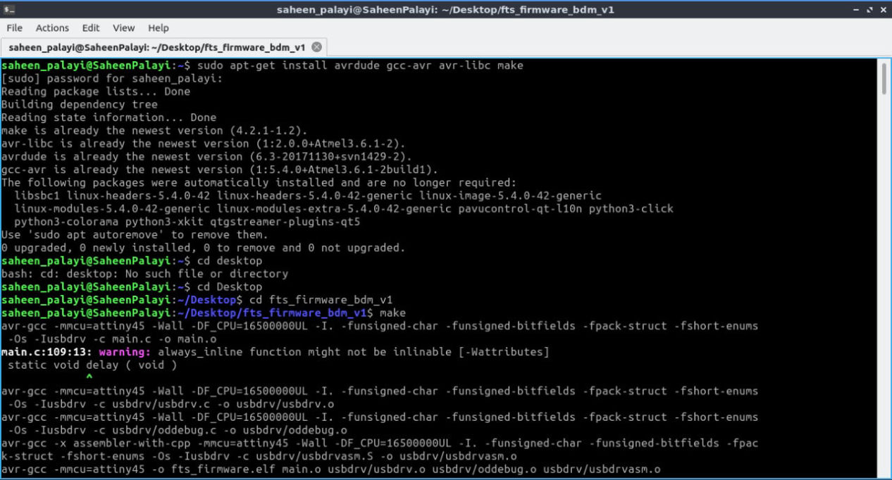
Now for testing there was a problem with windows on my PC so I used a linux system from my teammate's computer. Following steps were followed to program the programmer.
1. Open the terminal and enter following command followed by the password
sudo apt-get install avrdude gcc-avr avr-libc make
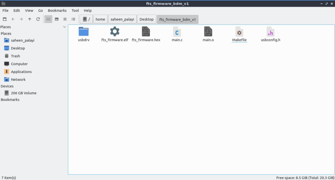
2. Download the firmware source code from the link.
3. Go inside the folder in the terminal where the firmware is saved and enter command below which should save hex file in the firmware folder
make
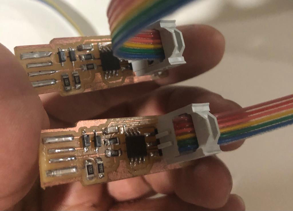
4. Now connect the ISP with the mother ISP which is already programmed via jumper cable. Connect in such a way that all the points in both the ISP are exactly same and connect it to the computer via USB port.
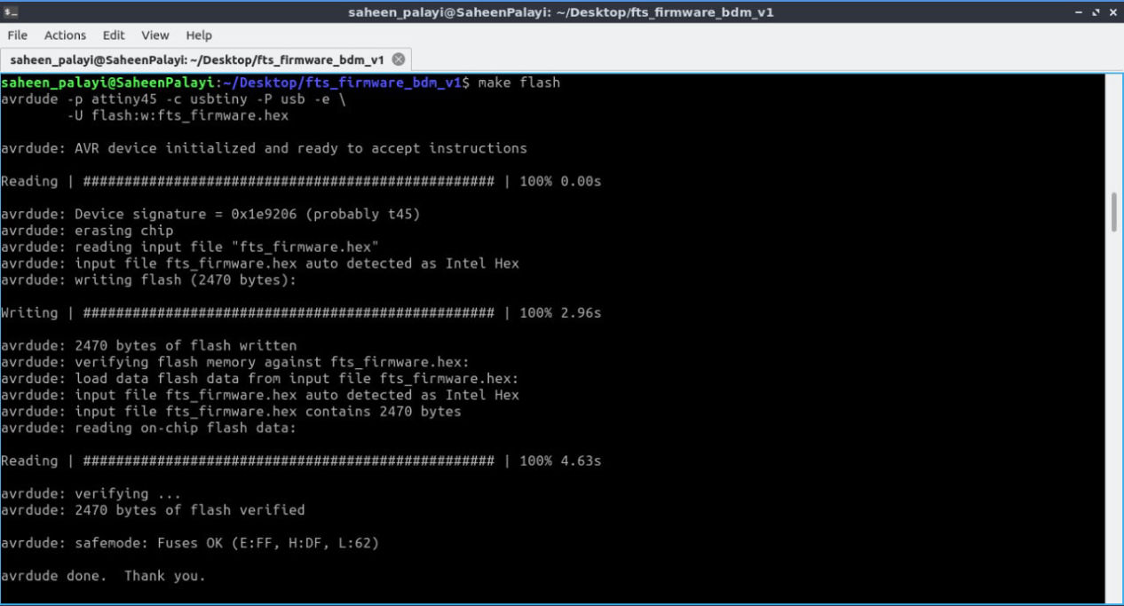
5. Load to the ISP by entering following code
make flash
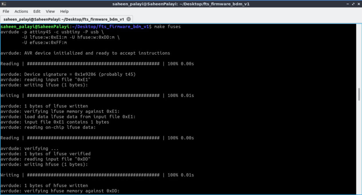
6. Fuse bits on the target chip by entering following code
make fuses
7. Check if the system recognizes your device by entering following code
lsusb
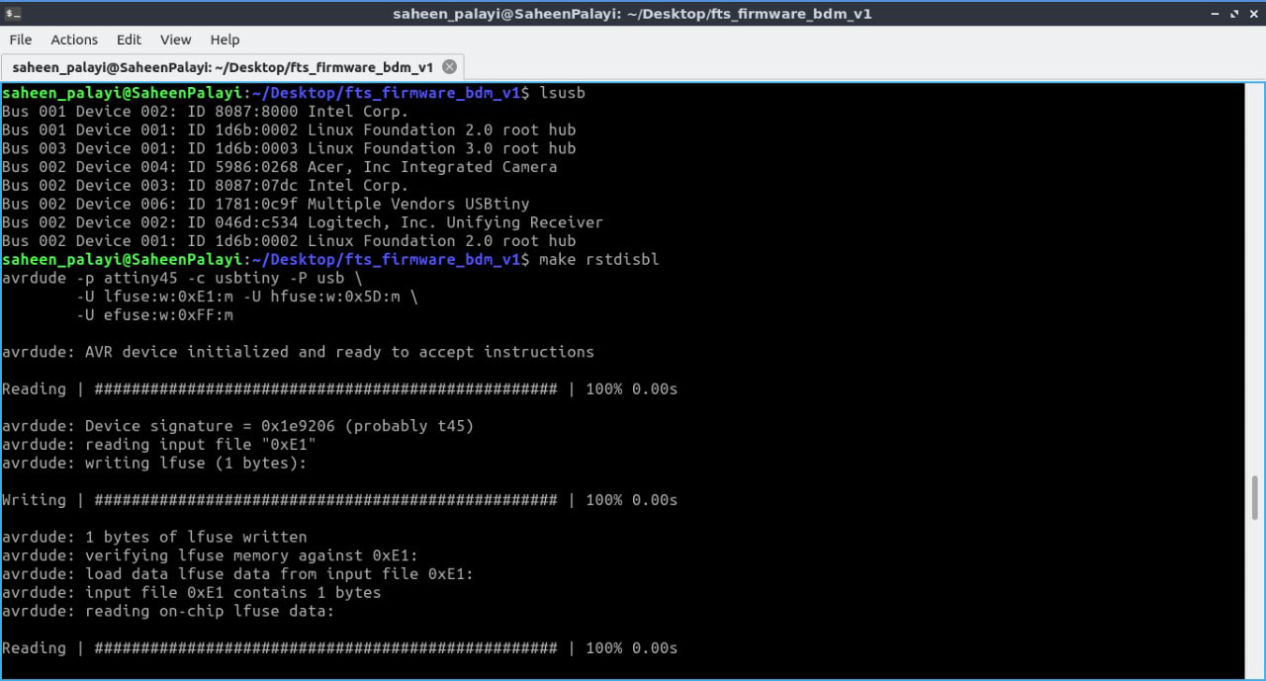
8. Now blow the reset fuse by entering following command like the image above and your ISP is now programmed
make rstdisbl
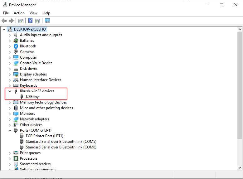
After all the process is finally done, you can also check whether your FABTiny ISP is connected or not by going inside device manager in your PC
Group assignment
As a group assignment, we have to characterize the design rules for your PCB production process. For this a standard file for milling is provided which you can download from below


Download it and follow the process below.
1. Load the material to be milled, add the tool for tracing, i.e. 1/64 inch mill and then set x, y and z axis.
2. Load the png file "linetest" you are going to trace from the download earlier.
3. Set the tool to 1/64 inch mill, set offset at 4, stepover 0.5 and speed 4mm/s, hit calculate and then open socket, open port and send the file which should start the cut.
4. Load the png file "linetest.interior" you are going to trim from the download earlier and using the milling tool of 1/32 inch mill, set same on the mods and execute the trim.
5. We did this using two mills of 1/64 inch and 1/32 inch and following results were obtained.
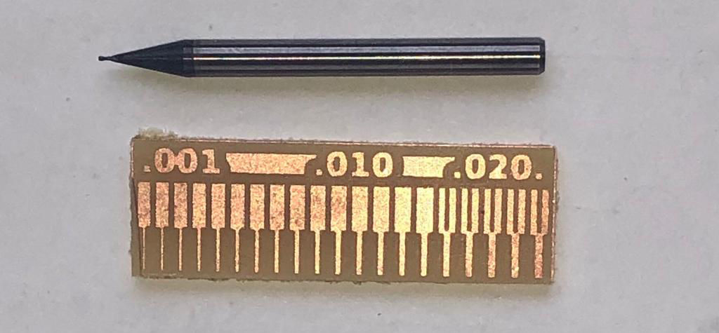
1/64 inch Mill
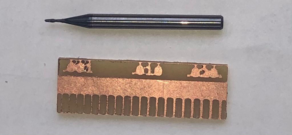
1/32 inch Mill
Designed with Mobirise free theme