Group
1. Compare as many tool options as possible
Individual
1. Write an application that interfaces a user with an input &/or output device that you made
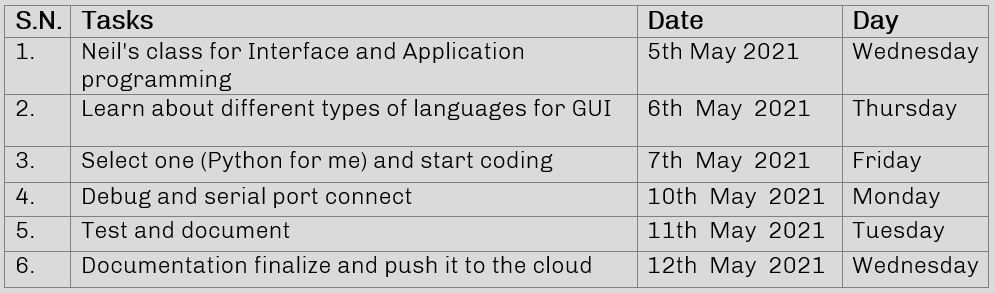
Plan for the week
This week, we are still in lockdown and our lab is closed but since this week is about programming and preparing the interface for the device that we have made in past week, it could be done from our home.
In general definition interface means a point where two systems, subjects, organizations, etc. meet and interact according to Oxford dictionary. In computing it means a device or program enabling a user to communicate with a electronics device. A device or program for connecting two items of hardware or software so that they can be operated jointly or communicate with each other is called interface,
Graphic User Interface (GUI):
According to Wikipedia, a GUI is a form of user interface that allows users to interact with electronic devices through graphical icons and audio indicator such as primary notation, instead of text-based user interfaces, typed command labels or text navigation.
In today’s times, graphical user interfaces are used in many devices such as mobiles, MP3 players, gaming devices, etc. We can see GUI in almost all the electronic components we use in daily basis like oven, washing machine, smart phones, printing tokens in banks, etc. These make use easy to understand and input the required information without displaying all the process going behind to perform the task.
Example of GUI in excel
In the figure above, he left side window is the user interface which is easy fro user to enter to find out the cost and adter he/she enters the data the calculation are happening on the right side window which gives back the value and the GUI window shows it.
The importance if GUI is to communicate with the user which and delivering the result to user by processing in a hidden background. This way the effectiveness of communication is better.
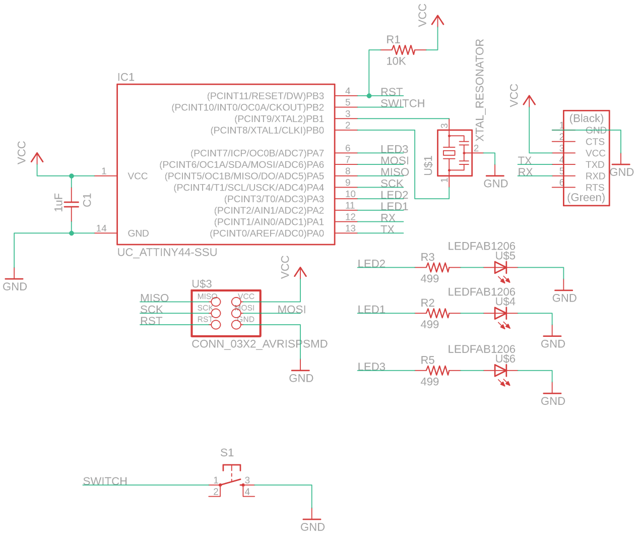
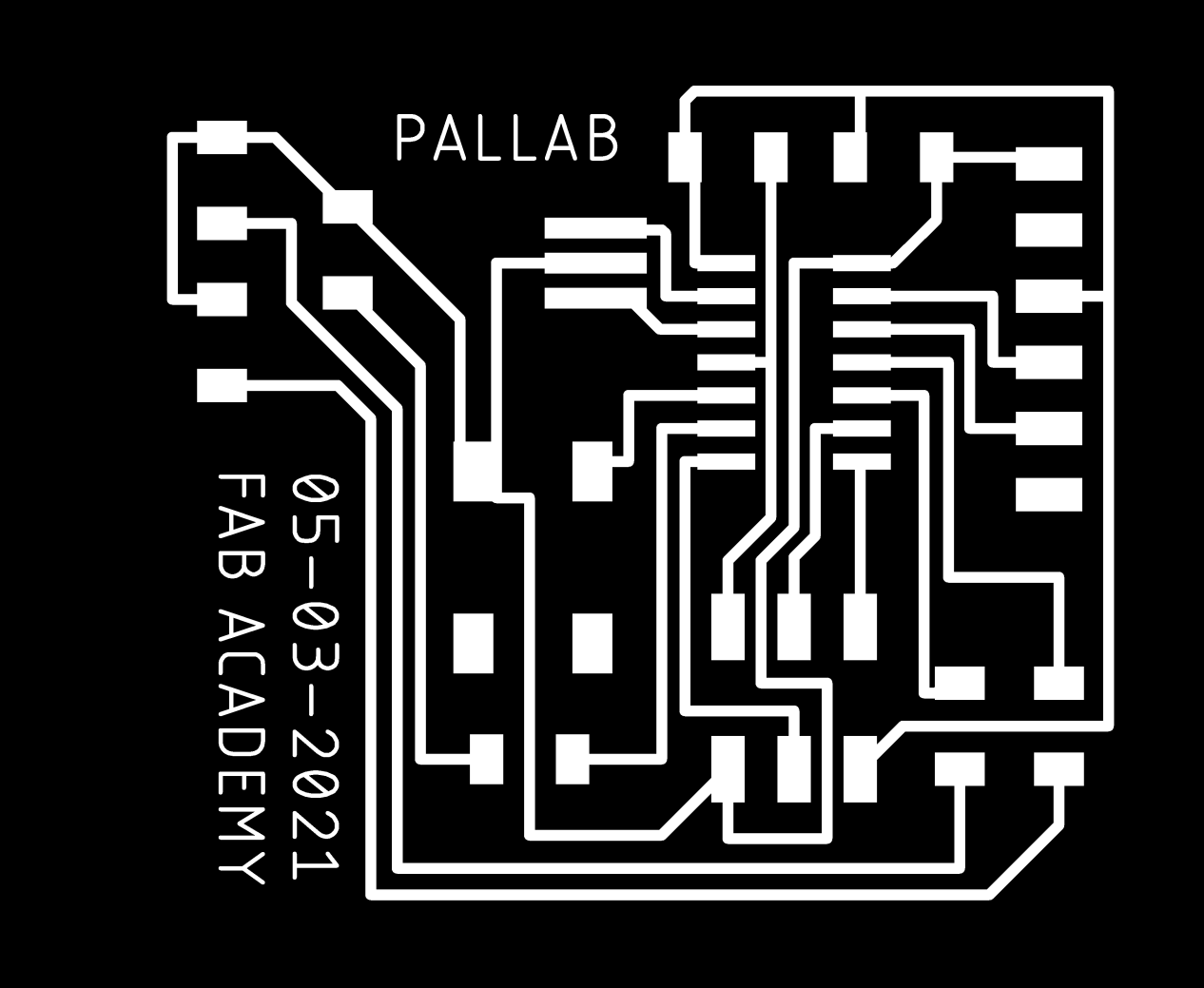
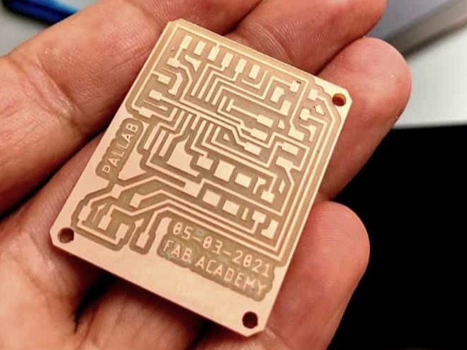
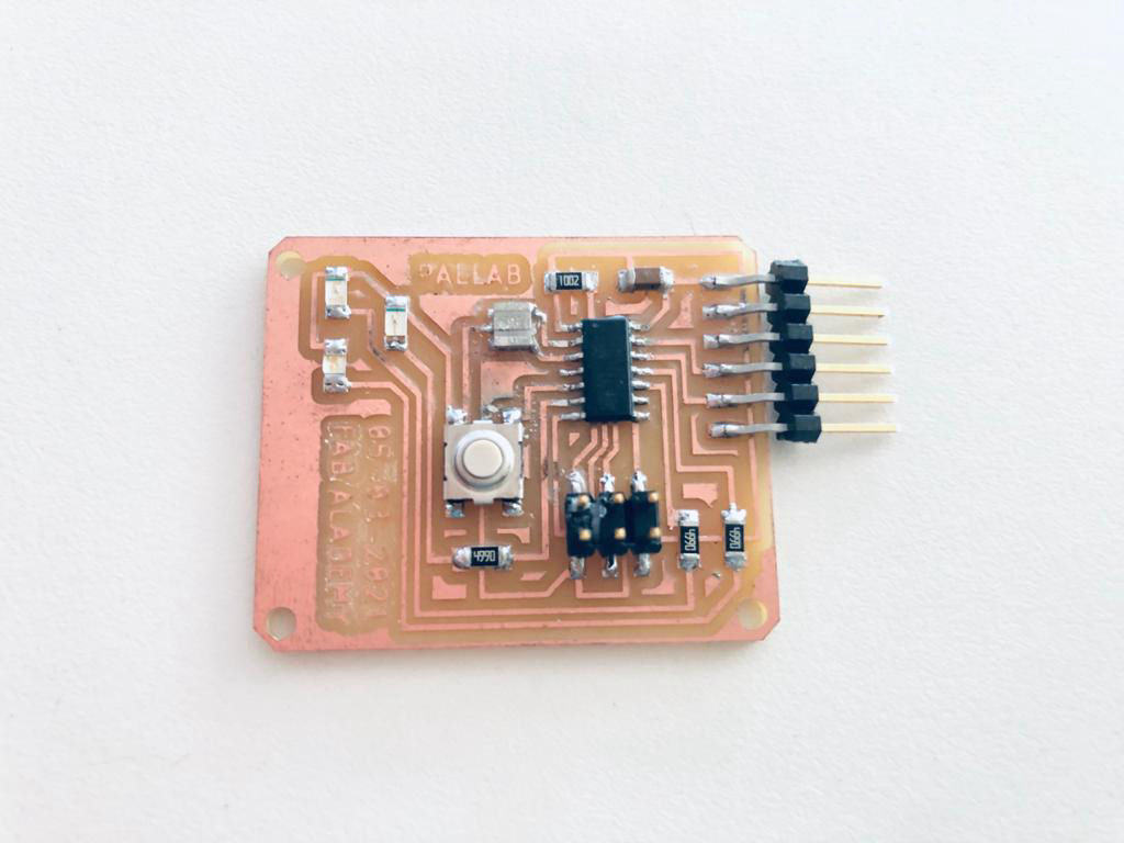
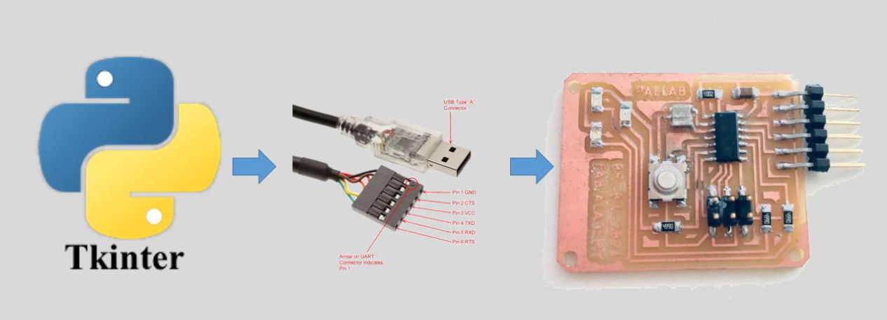
Board for interfacing
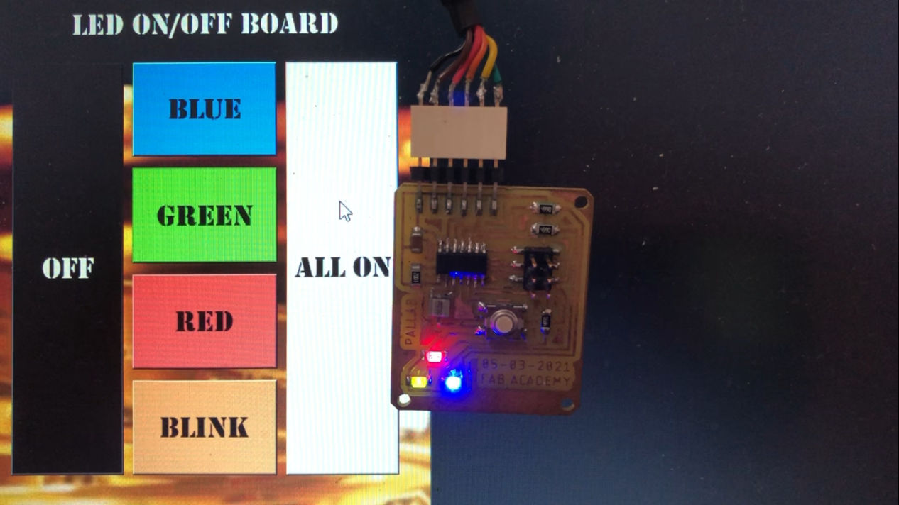
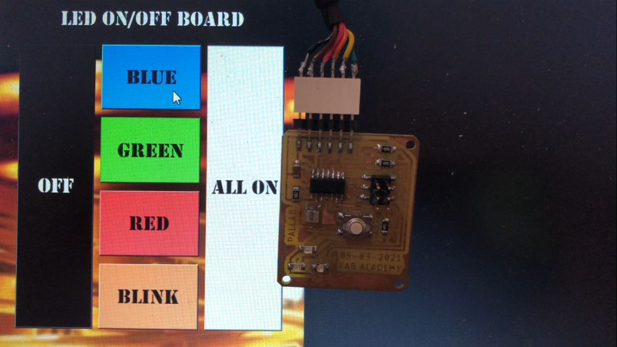
Since we were in lock down, we could not go to the the lab for making boards. Luckily, I had brought by previous boards as well as FTDI cable with me. I then wanted yo the board I made during the electronics design week which had 3 LEDs on the board. Here I was thinking to control the LEDs according to the buttons in GUI.
Following is the board I am using.
GUI Coding using python
I was always interested in python but never had chance to learn them and now when it is time to use it I am kind of blank as it is lockdown and I can learn it online only. But i knew that i could get any information in the internet and started researching about python, how to install it. Along with it I also came to know about tkinter which was the GUI part of python.
First you need to install python in you PC. For this, if you are a windows user click here to download of if you are using other system please click here.
It works on UART technology with CTS (Clear To Send) and RTS (Request To Send) connections to make the data more synchronized
UART
Universal Asynchronous Receive Transmit (UART) or Serial communication is one of the most simple communication protocols between two devices. It transfers data between devices by connecting two wires between the devices, one is the transmission line while the other is the receiving line. The data transfers bit by bit digitally in form of bits from one device to another. The main advantage of this communication protocol is that its not necessary for both the devices to have the same operating frequency. For example, two microcontrollers operating at different clock frequencies can communicate with each other easily via serial communication. However, a predefined bit rate that is referred to as baud rate usually set in the flash memory of both microcontrollers for the instruction to be understood by both the devices.
After python is installed you should download tkinter. For that either you can download it manually or download it from command prompt or powershell. I installed from command prompt. First open the command prompt and see your python version by using >> python --version
Then for tkinter >> pip install tk
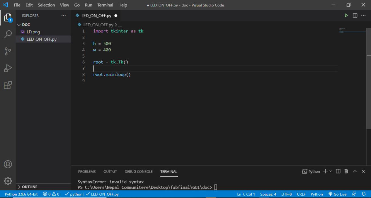
And tkinter will be installed in your computer and now you can use app of your choice which can compile and execute your python code. One of the commonly used application is PyCharm, but since I already had visual studio code, I will be using the same here as well.
Open Visual Studio and then on the mid left side there is extension toolbar and search python and if you don't have it you can proceed form next, if not install it. Then finally you are ready to start. First open a blank file and save it under *.py extension. Open it and start coding with >> import tkinter as tk
now you can use tk in place of whole work tkinter on the following program.
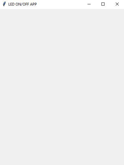
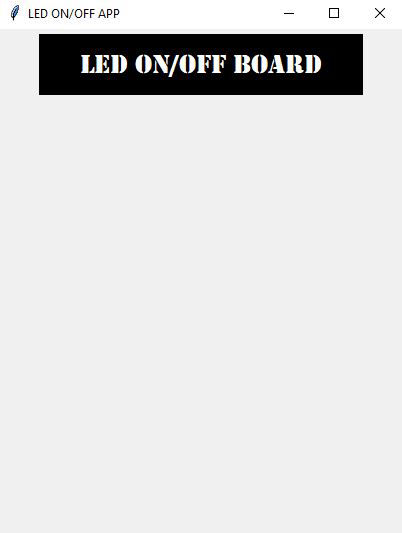
Make a blank window of desired size. for my app, i am thinking about having it 500 X 400 and make a root path where all the buttons, labels and components go in.on the first image below. here i have to inform you about pack, place and grid. when you use pack to put your widget, it organizes widgets in blocks before placing them in the parent widget. and the widget might or might not be in out exact position or if it does not matter it is ok to use it. However, in grit method, the geometry manager organizes widgets in a table-like structure in the parent widget. But, if you want to accurately place your widget in specific location, use place command. It organizes widgets by placing them in a specific position in the parent widget according to user. Now after you know about this lets start adding widgets.
Add background if needed using following functions
background_image = tk.PhotoImage(file='LD.png')
background_label = tk.Label(root, image=background_image)
background_label.place(anchor="n", relx=0.5, rely=-1.35, relwidth=4, relheight=4)
Now after all graphical things are done, add serial communication library and start the serial clock on the port you are adding your device to.
For library:
import serial
data = serial.Serial('COM3',9600) where data is the platform in which data is transferred.
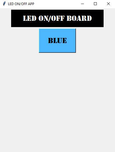
Finally add commands. First add command on the buttons, Example:
of = tk.Button(root, text="OFF", font=('Stencil',20), bg="black",fg="white", command=turn_led_off) , where command=turn_led_off is added.
Then define that command example:
def turn_led_off():
data.write(b'0')
This sends 0 to the serial port which you can see on the serial monitor.
Similarly do it for other colors also. blue: 1, green: 2, red: 3, all_on: 4, blink:5
And the GUI side is done!!!
To know more about tkinter and access the library and examples, follow this link.
Following is the full code for the GUI. you must have the device connected via port 3 for the file to be executed. Remember that the indentation is very important thing that you should follow in python.
import tkinter as tk
import serial
data = serial.Serial('COM3',9600)
def turn_led_off(): #This is to turn the LED off, we send one over the serial port and in the arduino code we turn the led off using digitalWrite
data.write(b'0')
def blue(): #This is to turn the LED on, we send one over the serial port and in the arduino code we turn the led on using digitalWrite
data.write(b'1')
def green():
data.write(b'2')
def red():
data.write(b'3')
def allon():
data.write(b'4')
def blink():
data.write(b'5')
h = 500
w = 400
root = tk.Tk()
# # Windows size height and width
root.title("LED ON/OFF APP")
canvas = tk.Canvas(root, height=h, width=w)
canvas.pack()
root.wm_attributes("-transparentcolor", 'grey')
background_image = tk.PhotoImage(file='LD.png')
background_label = tk.Label(root, image=background_image)
background_label.place(anchor="n", relx=0.5, rely=-1.35, relwidth=4, relheight=4)
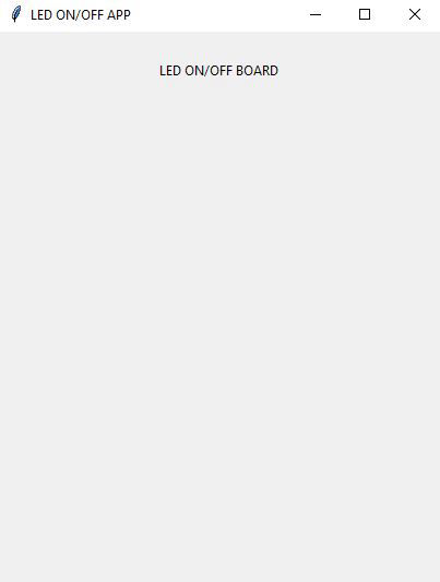
label = tk.Label(root, text="LED ON/OFF BOARD", font=('Stencil',20),bg="#000000", fg="white")
label.place(relx= 0.1, rely= 0.01, relwidth=0.8, relheight=0.12)
of = tk.Button(root, text="OFF", font=('Stencil',20), bg="black",fg="white", command=turn_led_off)
of.place(relx= 0.07, rely= 0.14, relwidth=0.25, relheight=0.74)
bl = tk.Button(root, text="BLUE", font=('Stencil',20), bg="#4db8ff", command=blue)
bl.place(relx= 0.34, rely= 0.14, relwidth=0.32, relheight=0.17)
gr = tk.Button(root, text="Green", font=('Stencil',20), bg="#4dff4d", command=green)
gr.place(relx= 0.34, rely= 0.330, relwidth=0.32, relheight=0.17)
rd = tk.Button(root, text="RED", font=('Stencil',20), bg="#ff4d4d", command=red)
rd.place(relx= 0.34, rely= 0.52, relwidth=0.32, relheight=0.17)
gr = tk.Button(root, text="BLINK", font=('Stencil',20), bg="#ffa64d", command=blink)
gr.place(relx= 0.34, rely= 0.710, relwidth=0.32, relheight=0.17)
wh = tk.Button(root, text="ALL ON", font=('Stencil',20), bg="white", command=allon)
wh.place(relx= 0.68, rely= 0.14, relwidth=0.25, relheight=0.74)
root.mainloop()
Programming in Arduino IDE of the Board
#include
const int ledPin1 = 2;
const int ledPin2 = 3;
const int ledPin3 = 7;
SoftwareSerial Serial(0,1);
void setup() {
// put your setup code here, to run once:
Serial.begin(9600);
pinMode(ledPin1, OUTPUT);
pinMode(ledPin2, OUTPUT);
pinMode(ledPin3, OUTPUT);
}
void loop() {
// put your main code here, to run repeatedly:
int data=Serial.read();
switch (data){
case '0':
digitalWrite(ledPin1,LOW);
digitalWrite(ledPin2,LOW);
digitalWrite(ledPin3,LOW);
break;
case '1':
digitalWrite(ledPin1,HIGH);
break;
case '2':
digitalWrite(ledPin2,HIGH);
break;
case '3':
digitalWrite(ledPin3,HIGH);
break;
case '4':
digitalWrite(ledPin1,HIGH);
digitalWrite(ledPin2,HIGH);
digitalWrite(ledPin3,HIGH);
break;
case '5':
for(int x=0; x<20; x++){
digitalWrite(ledPin1,HIGH);
digitalWrite(ledPin2,HIGH);
digitalWrite(ledPin3,HIGH);
delay (50);
digitalWrite(ledPin1,LOW);
digitalWrite(ledPin2,LOW);
digitalWrite(ledPin3,LOW);
delay (50);
}
}
}
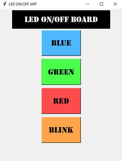
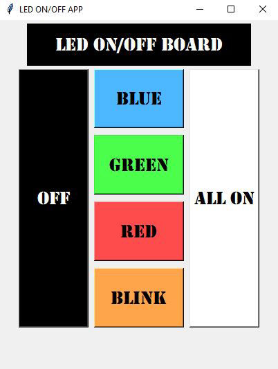
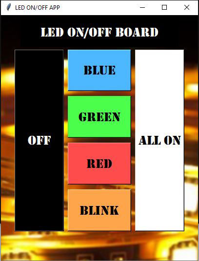
The user Interface that I created was like this where there are six functions for the 3 LEDs on the board
There were many problems as this was the first time I was coding on python but by resolving all the issues at last the application worked
Augmented Reality (AR)

I was thinking to use AR for this my documentation so as to save some space. I was exploring about AR, how to create and link and I came across this beautiful app called Artivive. I used this to create an AR effect to my picture. We just have to do is make an account in Artivive from the link above. Then add photo and video which you want to link to the photo.
Then please install artivive in android or iOS and hover it over the image you have uploaded in the server. If the image is link in the server anyone can see the AR from the image if the app is installed
Why dont you try installing the app, open it and hover around the image below. This will let you know what happens when you use the GUI.
Group Assignment:
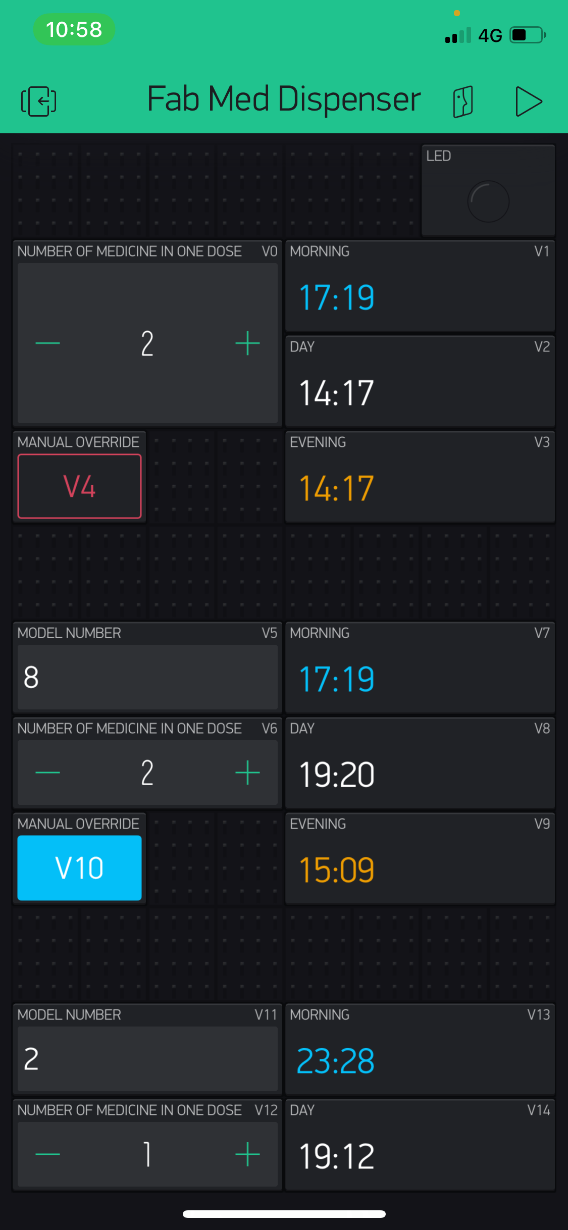
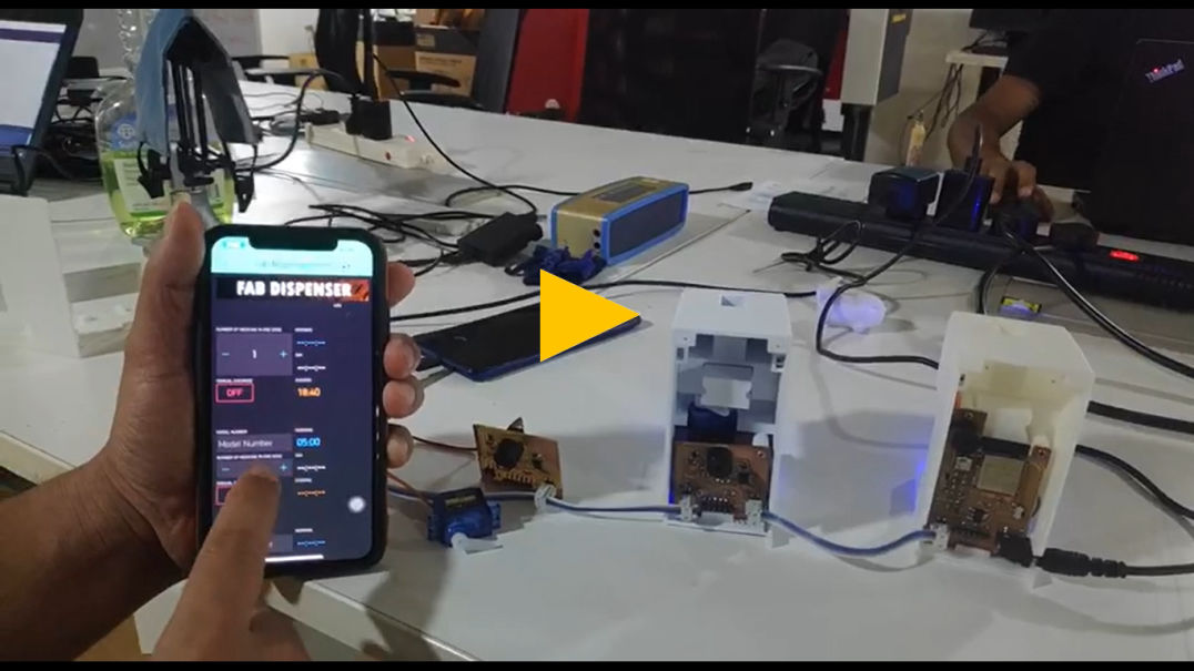
I also used Blynk for my final project as well where the board with WiFi capability (ESP-32) was used. I am using Blynk application for setting time, quantity and model number for the secondary as well.. As this application is easy to use and have been used in other IOT devices, I decide to use it for the first phase and during the futher development of the product, dedicated application can be made from platforms like AppInventor, Thunkable, etc. There is a simiilar platform that is offered by arduino as well which you can try from this link.
Blynk IoT platform offers a full suite of software allowing to prototype, deploy, and remotely manage connected electronic devices at any scale: from small IoT projects to millions of commercial connected products. With Blynk, you can connect hardware to the cloud and use pre-made app modules to build iOS, Android, and web applications ready for the end-users. In short, Blynk is an “Internet of Things” (IoT) platform that allows you to build your own apps to control certain devices over the internet.
Steps for using Blynk
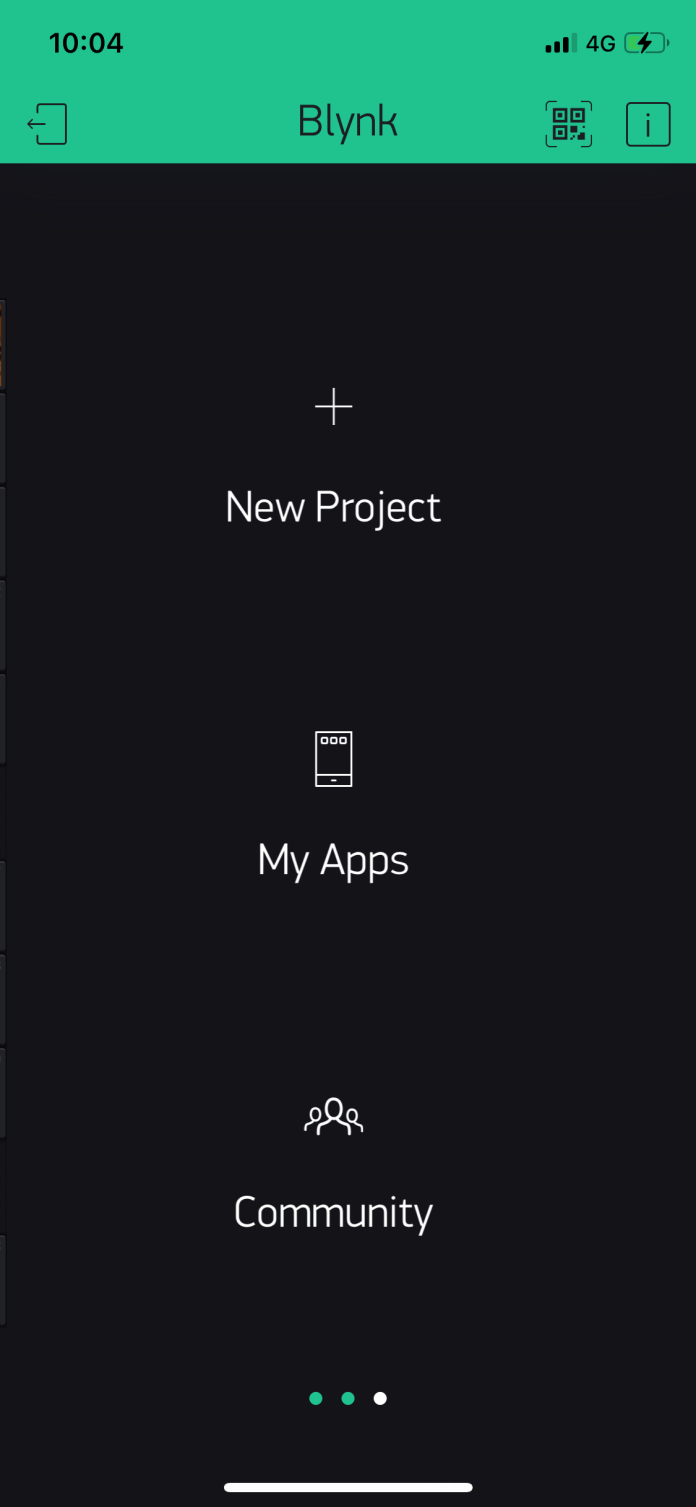
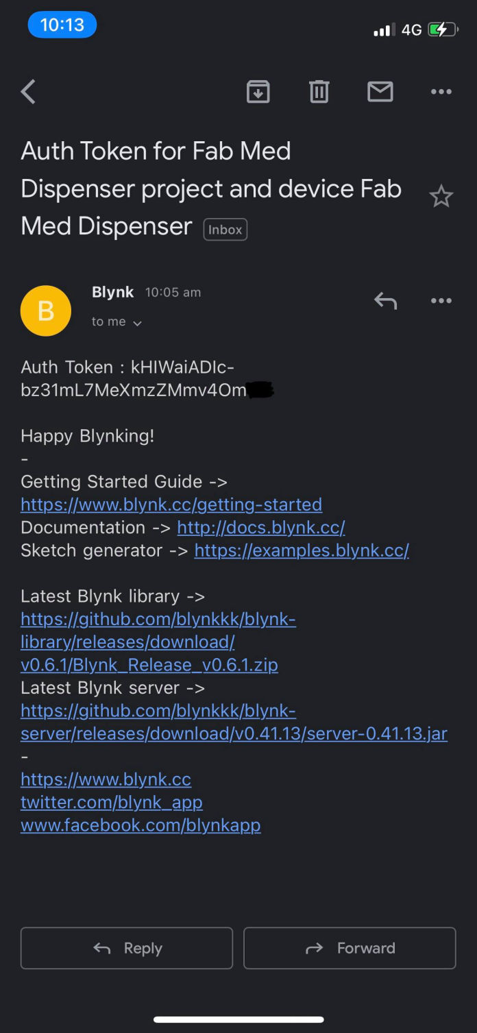
It is very easy to use Blynk. First you have to download the application from app store if you are an iPhone user of google play if you are using android. I am using iPhone so will be giving example on that one. After you download the application see the step below how I created the application
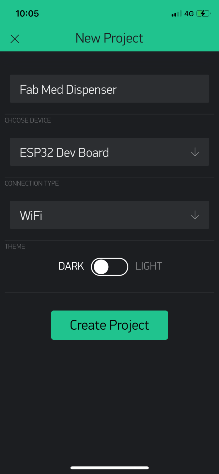
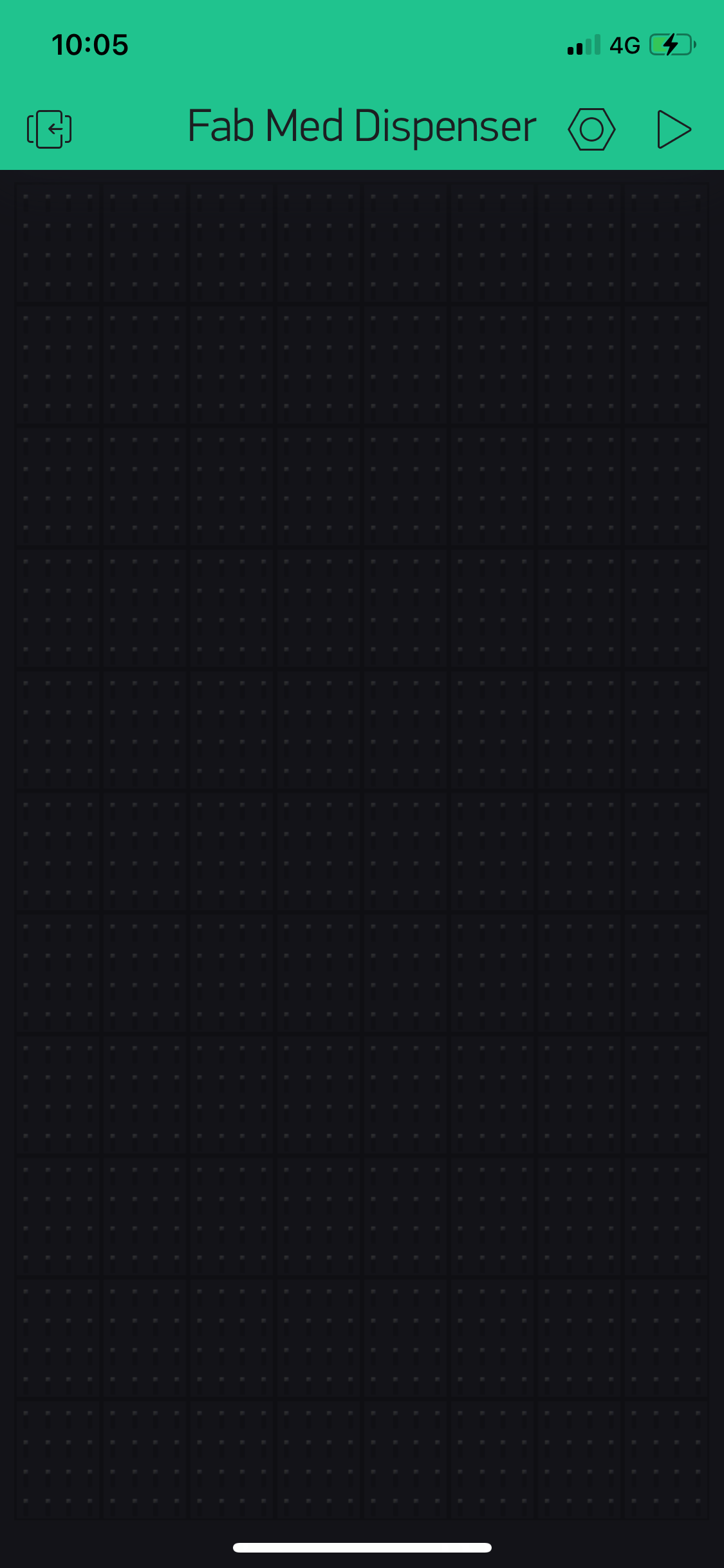
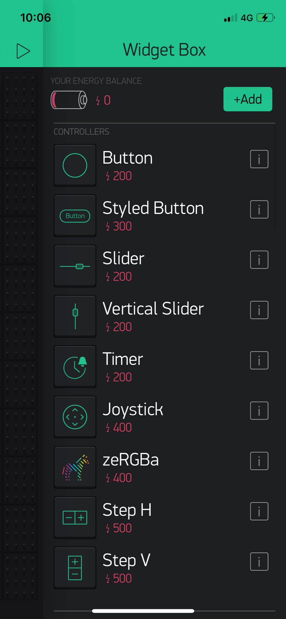
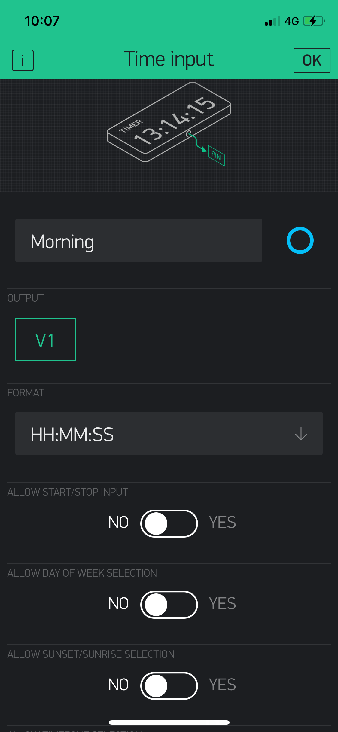
After arranging different widgets here and there you will get to the layout suitable for you. For me the layout shown below was the required one.
For codes please refer this link to download from Networking and communication week
How to make a free website - Click for more