Individual:
1. Model (raster, vector, 2D, 3D, render, animate, simulate, ...) a possible final project, compress your images and videos, and post it on your class page
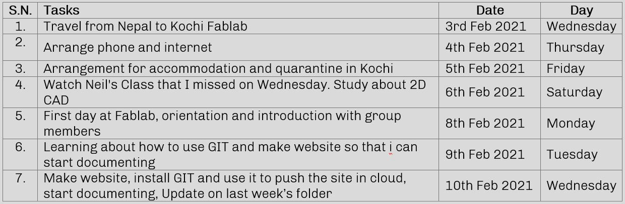
Plan for the week
2D design involves design with drawings in one plane with only 2 axis, X and Y axis. Now in order to communicate design, we need an output device. The device that we use to visualize the design is made up of pixels. So in order to visualize the design, we have to assign input to the pixels in two ways either by defining value to each pixel which is called raster graphics or by defining different geometry according to which pixels is defined by series of points to be connected which is called vector graphics.
Raster graphics
This is the type if graphs which operates by assigning value to each pixel which generate a specific color. We can get raster images commonly while capturing image from devices like camera, scanner, etc. Raster graphics are made up of a finite number of pixels that take up a specific amount of space. In this kind of images, if you take a small photo and enlarge it, it will become more and more pixelated and more blurry until it reaches the point where it is unrecognizable. The size of the image depends upon the image quality and image size. Some common formats are: .jpg, .bmp, .tif, .gif, .png, etc. Some software related to raster graphics are Photoshop, Gimp, Bimp, Pixlr, Photofiltre, Krita, etc. Download file
Vector graphics
This is a type of graphics where the image is defined by geometries or shapes which allow them to scale in any size you want without losing the details. The boundaries for the colors are defined by mathematical curves. This uses commands which describes a series of points to be connected, hence have a crisp output even when it is enlarged. We can normally find these type of image in documents like pdf or logos and are heavily used and preferred by graphic designers are they are editable as well as perform well under scaling. They are relatively less in size as compared to raster images. Some software related to vector graphics are Illustrator, Skechpad, Inkspace, Coreldraw, Freecad etc. Download file
Converting form raster to vector file
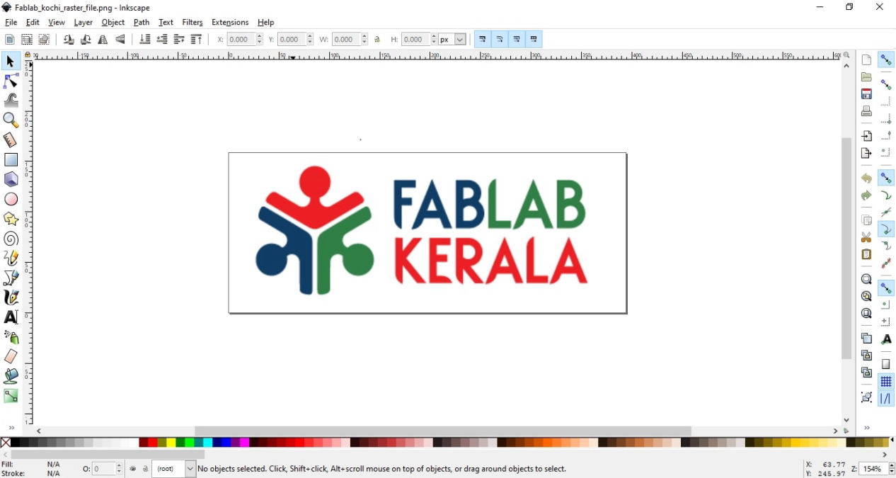
I used two of the softwares to test which performs well. One is Inkscape and another adobe illustrator. I had been using illustrator previously to convert images to into vector to carve it in the wood using Handybot back in Nepal. Inkscape was new to me. Then after installing Inkscape which as an opensource software, I tried to convert the logo of Fablab Kerala from the raster image that i downloaded from internet to the vector.
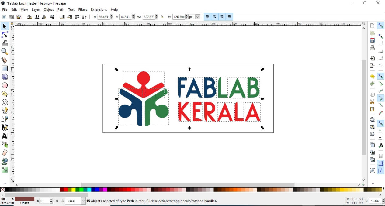
Inkscape
1. Import the file to Inkscape
2. Select the file by left clicking it and click on Trace Bitmap inside the Path toolbaar
Path >> Trace Bitmap
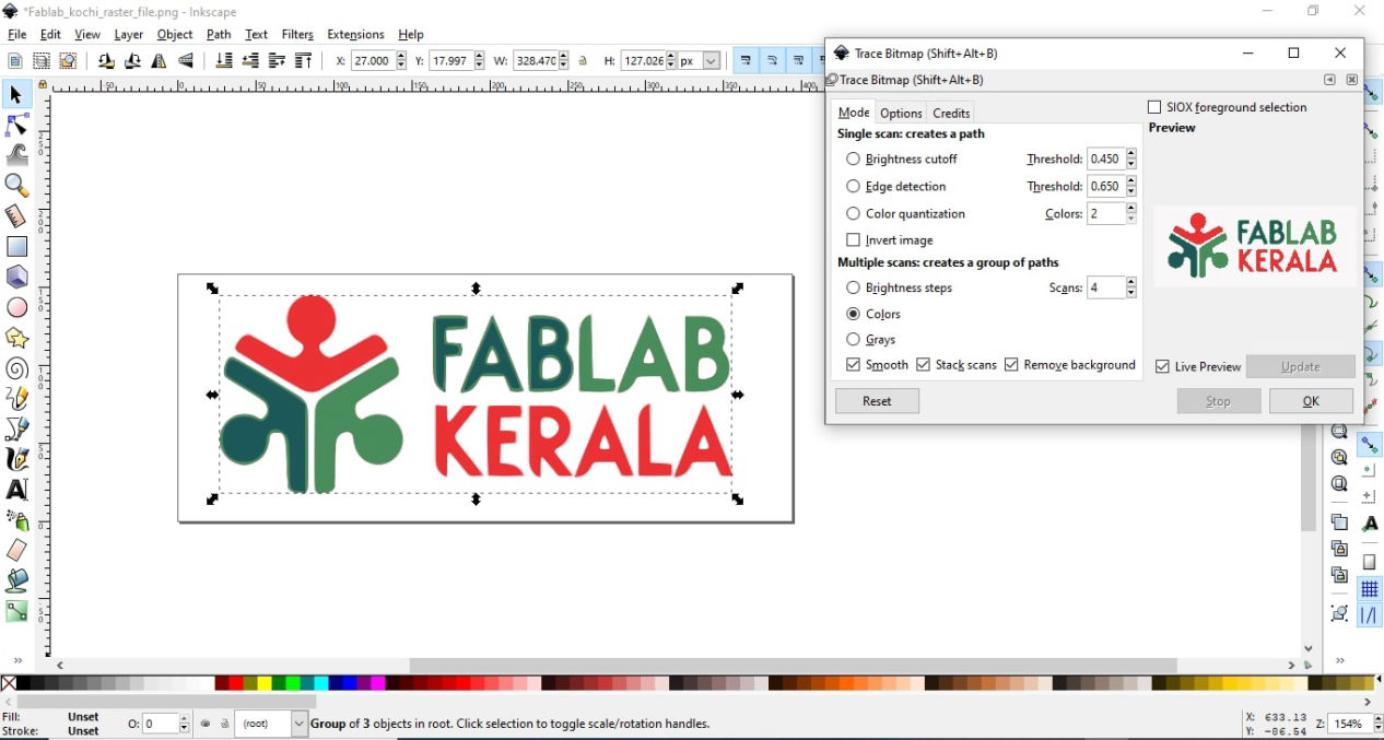
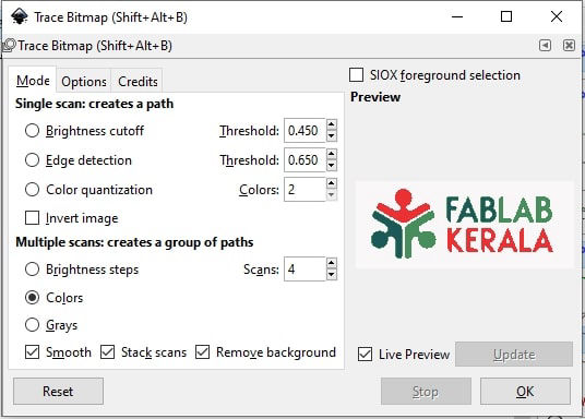
3. Toggle between options to trace according to you need. I wanted color to be remained inside the vector file and selected colors options with 4 scans to get all the colors. This resulted in 3 layers if we ignore the background. So to get single colored vector I had to go through 3 process after using brightness cutoff option: a. Use Break apart (inside path) to break all the characters, b. Use difference (inside path) in case of characters like "A" c. Select a group of vector and use dropper to pick up color.
Save the image on your desired format like .svg
Adobe Illustrator
1. Import the photo, Left click the photo and click on Image Trace inside Window tool on the toolbar
Window >> Image Trace
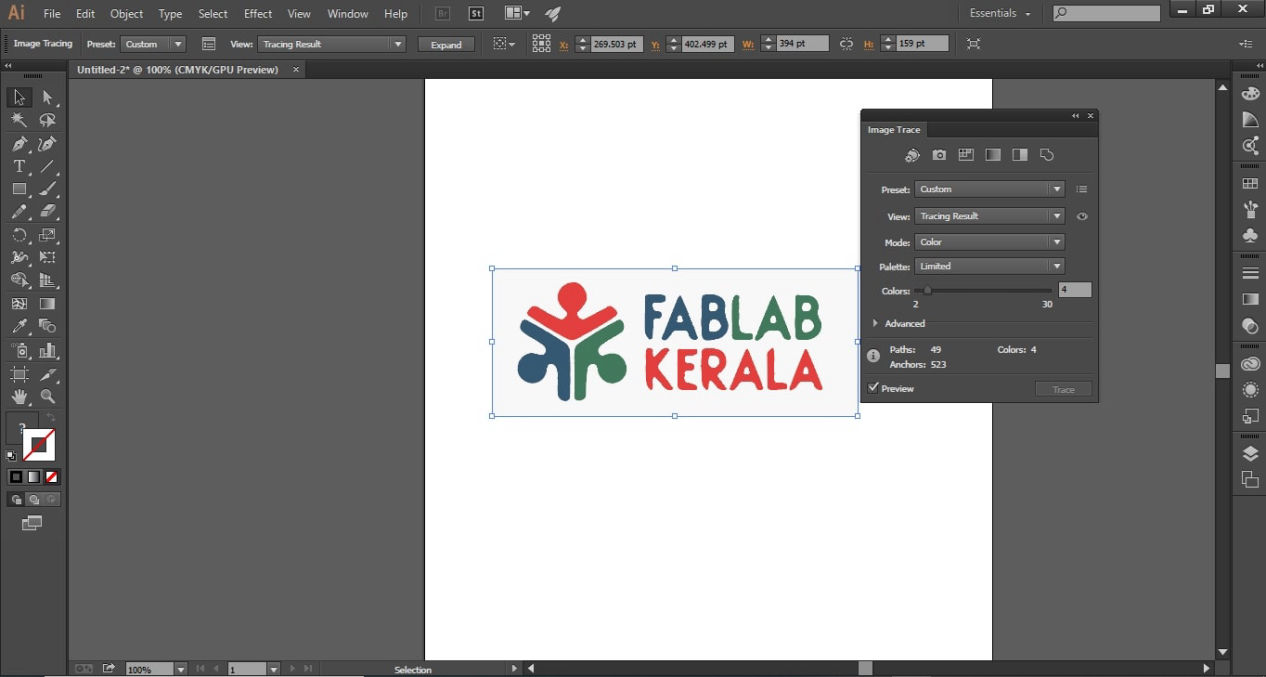
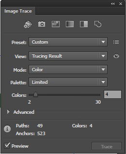
2. Inside the Image Trace window, toggle between option to get best result but for this case, select Tracing result in View and input 4 in the colors option and hit trace.
View >> Tracing result
colors >> 4
3. Press expand and save the image as per desired format like .svg
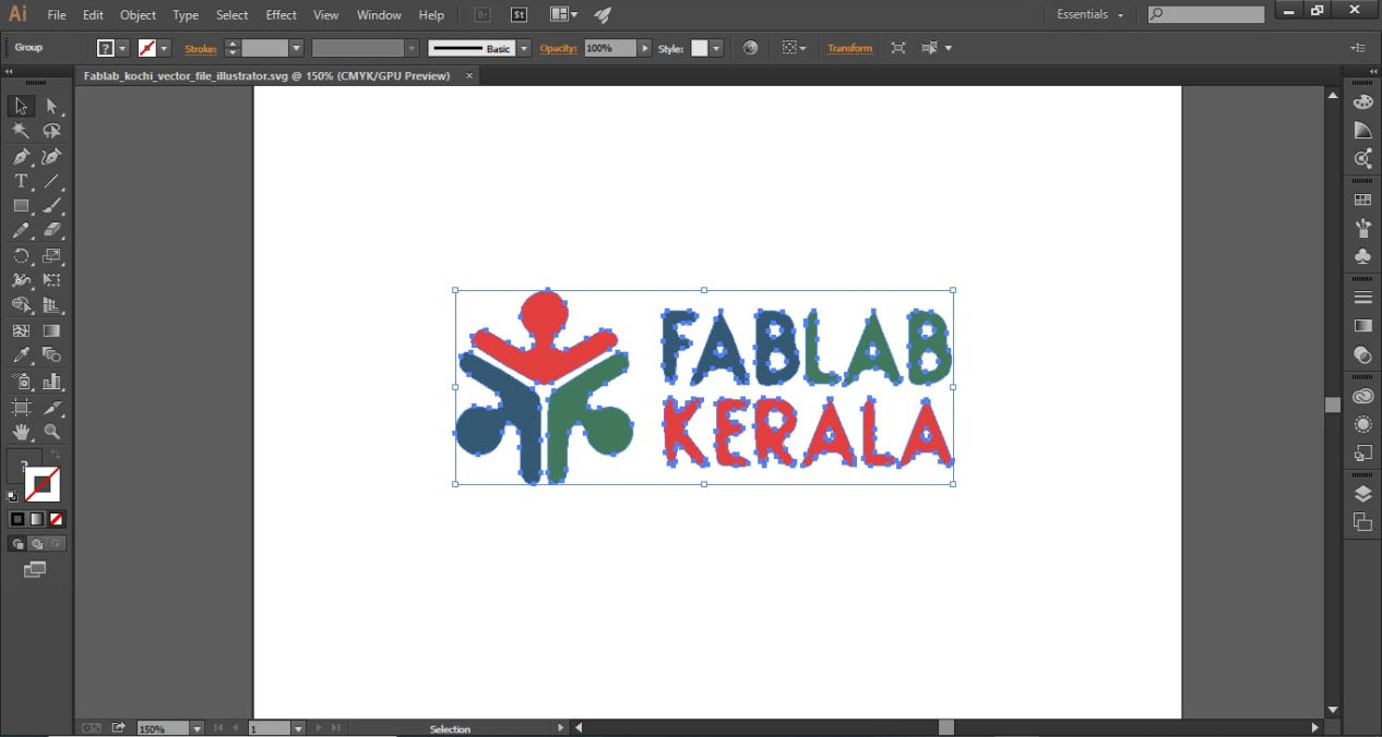
Comparing these two software, both had pros and cons like Inkscape being less complex and open source while illustrator more complex with more capability and fast result. I will be mostly using illustrator but will keep Inkscape as an option use it depending upon the accuracy final vector output as compared to original raster file.
3D CAD
According to Autodesk, 3D CAD, or three-dimensional computer-aided design, is technology for design and technical documentation, which replaces manual drafting with an automated process. Used by architects, engineers, and other professionals, 3D CAD software precisely represents and visualizes objects using a collection of points in three dimensions on the computer. Dassault systemes are trying to 3D CAD solutions which let you conceptualize, create, validate, communicate, manage, and transform your innovative ideas into great product designs.
In my definition, 3D CAD is the technology which uses points to make curves, curves to make surface and surfaces to make geometries, shapes, surfaces and solid in a 3 dimensional space visualized in 3D platform of a software in a 2D screen of a computer. As only 2D drawings needs some extra process to visualize and understand, 3D shapes are very much relatable and are easy to understand by humans. This ease of understanding brings clarity to design communication and expressing what you want from your head to actual visual 3D shape.
There are many types of CAD software in market, some are free and some comes with low to very high license cost depending upon its capability, use and ecosystem around it.
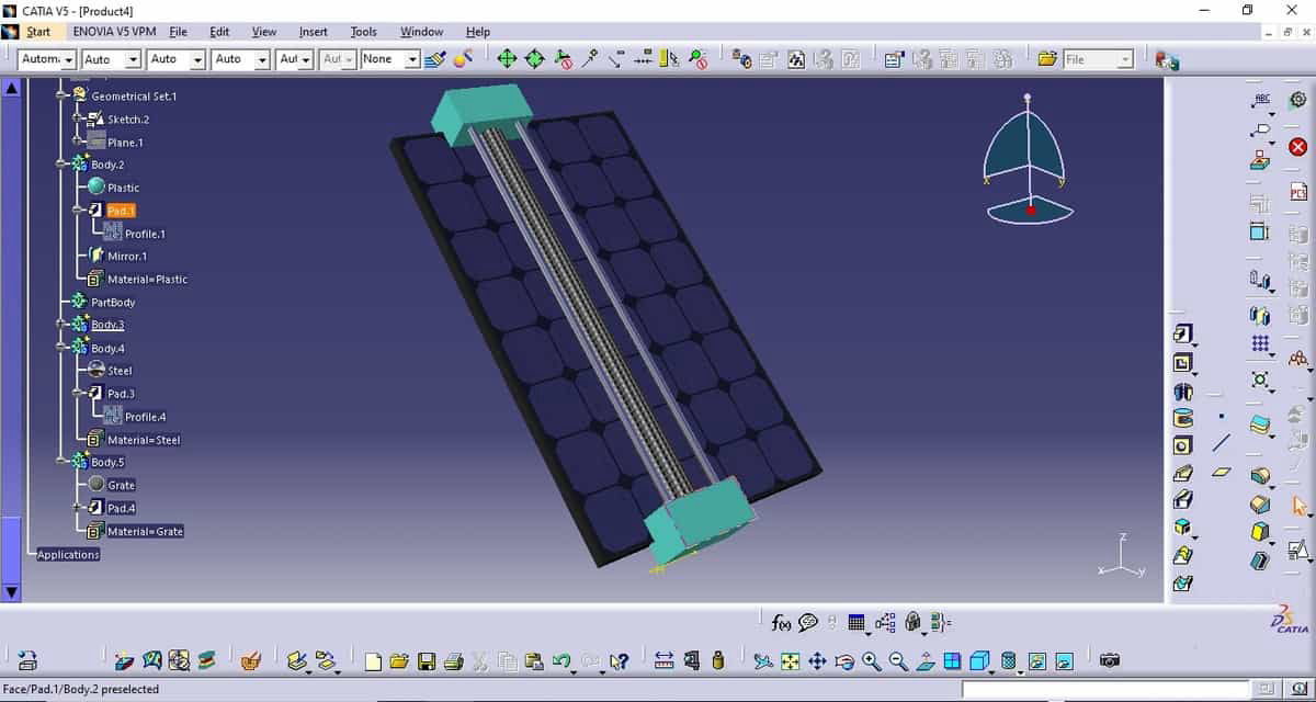
I have used CATIA intensively during my work and Solidworks for the training purposes. However I used fusion 360 and used Solidworks more as to understand about them.
One important thing for you to know is that once you know one 3D CAD, you would know about the features and tools to make different shapes and geometries which helps a lot while shifting to another CAD software. The only things that you have to learn is about the location of those tools in each 3D CAD software and shortcuts for working efficiently. However, the add-on that each software have might me different and I was fascinated by fusion-360 as it can incorporate CAD with PCB design, CAM, rendering and 3D printing.
Personally, After using all three software, maybe due to my previous experience, I still think for the making part and about capability for making shapes tree management, CATIA is what I like, then comes Solidworks. Solidworks on the on the other hand have their special licenses in education field and are good for training. The best thing I like About fusion 360 is its sharing possibilities and post 3D design phase. I will be using all three software to learn more about them and use STEP file, a universal exchange file to swap between software.
Meanwhile, I have tried to share you process for 3D modeling in Solidworks below.
1. Open the file Handsfree handle initial.sldprt.
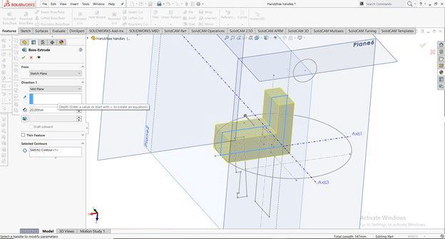
2. Left Click (LC) on the Extruded Boss/ Base feature on the feature toolbar
3. Select the sketch that you want to extrude from (i.e. sketch2) Click on the blind command below direction 1 which should display different ways to extrude.
4. LC on Mid Plane and insert 20 mm in the dimension command box and hit OK.
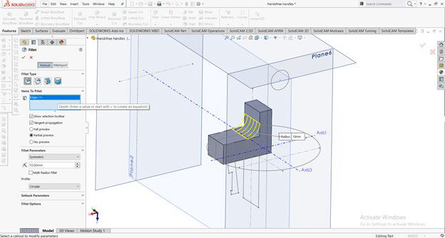
5. LC on the fillet feature on the feature toolbar
6. Select the edge as given below in the image in the Item to fillet and enter 20mm in the fillet parameter and hit OK.
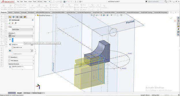
7. LC on the Extruded cut feature on the feature toolbar
8. Select the sketch you want to cut with (i.e. sketch 6)
9. Keeping the selection to blind insert 50 on the dimension (you can insert any length unless it cuts through the shape you are going to cut)
10. A preview on yellow shape would be seen. Change the arrow direction if needed by pressing the arrow key on the direction 1 on the left side where blind is written and hit OK
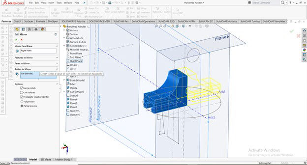
11. LC on the Mirror feature on the feature toolbar
12. On the mirror face either select the Right plane or the right face of the shape you want to mirror about.
13. Now, LC on the blank box in the bodies to mirror command and select the body on the screen.
14. A yellow preview will be seen on the screen for verification and hit OK.
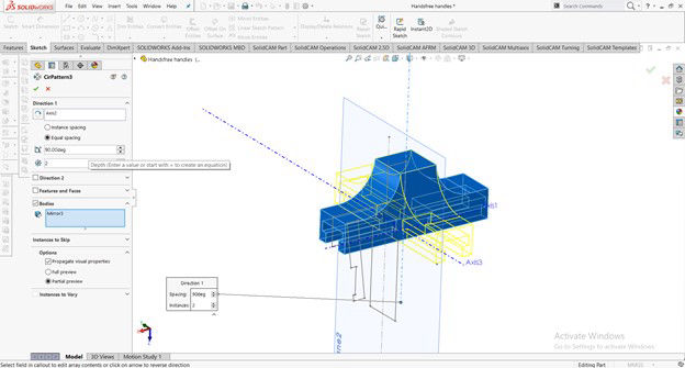
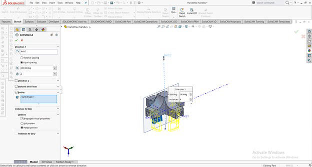
15. LC on the arrow on the right side of the linear pattern and select the Circular pattern.
16. LC on the blank space just below the Direction 1 on the right side of the picture showing clockwise-anticlockwise arrow and select the axis of rotation (i.e. vertical axis or axis 2)
17. Uncheck features and face and check on Bodies and select the body on the screen (which should show mirror 3 in the box) and a yellow preview should be seen on the screen for verification and hit OK
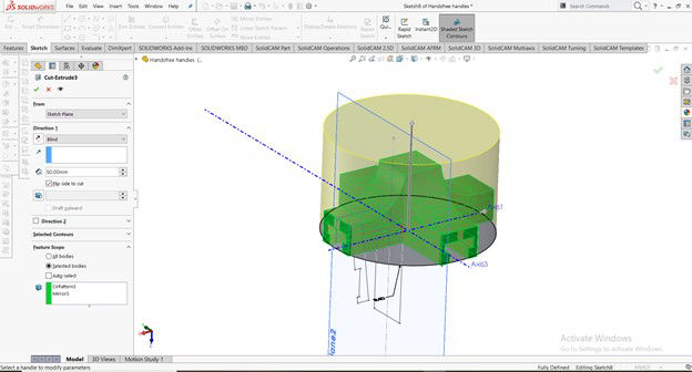
18. LC on Extruded cut on the features toolbar and select the sketch of circumferential circle (i.e. sketch 8) for cutting the edge of the shape
19. Keeping the selection to blind insert 50mm on the dimension command
20. Check the box in Flip the side to cut and click both the main body and rotated body in the feature scope and the bottom of the command window of extruded cut and hit OK
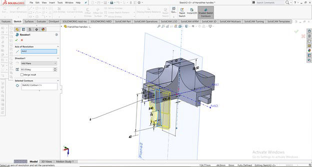
21. LC on the Revolved Boss/Base on the features toolbar and select the sketch to revolve (i.e sketch 2)
22. Choose vertical axis that is Axis 2 on the Axis of revolution
23. LC on the Blind below Direction 1 and select Mid plane so that we have symmetry of the shape on both sides of the sketch and enter 60 Deg of the angle command.
24. Remember to uncheck the merge result command so that it remains as a different body (i.e movable jaw for clamping) and hit OK.
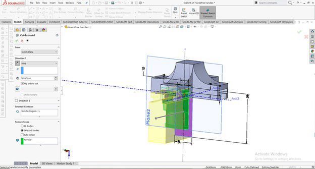
25. LC on the Extruded cut on the feature toolbar and select Sketch 6
26. Keeping the selection to blind insert 50 on the dimension (you can insert any length unless it cuts through the shape you are going to cut)
27. A preview on yellow shape would be seen. Change the arrow direction if needed by pressing the arrow key on the direction 1 on the left side where blind is written.
28. Since we want to cut outside of the shape, LC on the checkbox of flip side to cut and hit OK.
29. LC on the arrow on the right side of the linear pattern and select Circular pattern.
30. Click on the vertical Axis (i.e Axis 2), check on Bodies and select the lower law which should show you the preview of how pattern will be done and press OK
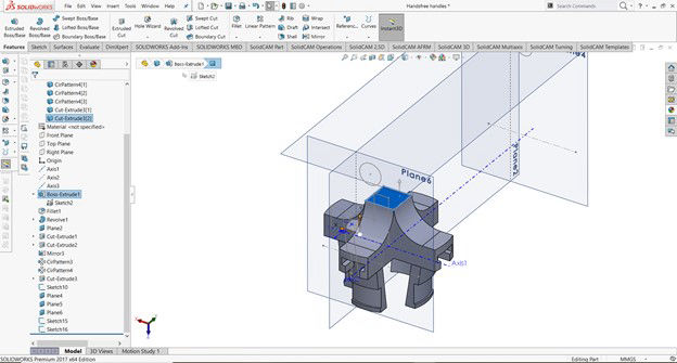
31. LC on the top surface of the body shown in blue and press sketch feature on the features toolbar inside sketch.
32. Keep pressing CTRL on your keyboard and LC on four edges of the top square and release CTRL.
33. LC on the arrow below convert entity and LC on intersection curve which should give you the lines making square on the sketch
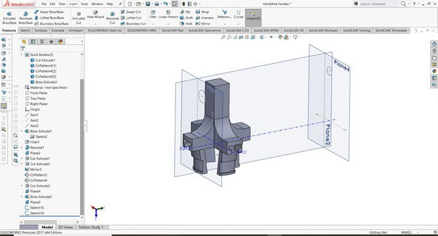
34. Click on the Extruded Boss/Base feature on the feature toolbar and select the sketch made on the top of the handle (i.e Sketch you created on the last step)
35. LC on the blind option which should give you other options to extrude. Select Up to Surface and select plane 5 and hit OK
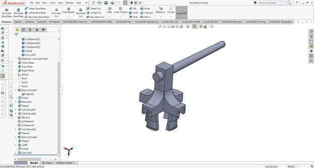
36. LC on the Lofted bose feature where the blank area of profile should be highlighted blue.
37. LC on the edge of the circle of sketch 15 and again LC on edge of the circle of sketch 16, adjust the guide according to the smoothness of the shape and click ok.
38. Do the same with the Lofted cut selecting as before and should make a hole in the main body.
39. Apply a fillet of 5mm on the far tip of the handle to make it smooth.
Finished!!!
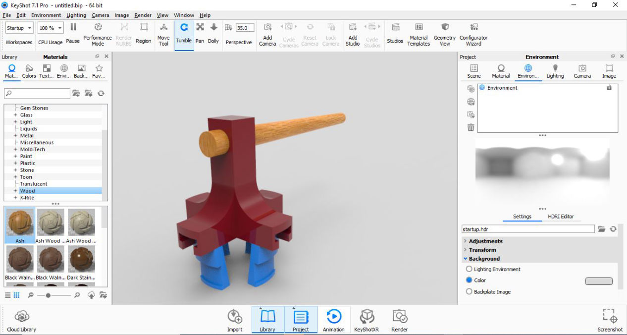
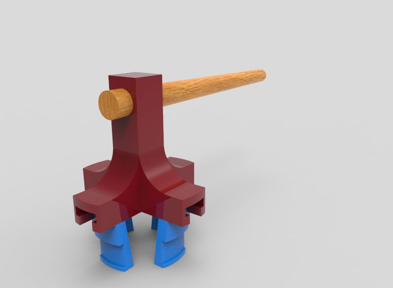
Rendering
The process of generating a photorealistic or non-photorealistic image from a 2D or 3D model by means of a computer program. The resulting image is referred to as the render. Different CAD have different inbuilt render engine which can be used. However there are software which are either only for rendering or at lease dedicated to rendering like Keyshot, Blender, Maya, etc. I have used Keyshot here. The manual for using keyshot can be downloaded here.
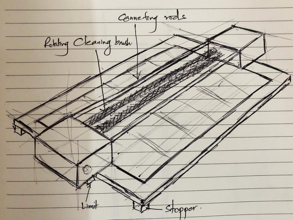
CAD for final project
This site was started with Mobirise