13. Networking and communications
individual assignment:
design, build, and connect wired or wireless node(s) with network or bus addresses
group assignment:
send a message between two projects
Files
This is the reciever board:
And this is the transmitter board:
3105 solar RF sensor REV.15 atmega328 sending board to be manufactured.brd
3105 solar RF sensor REV.15 atmega328 sending board to be manufactured.sch
And these are the codes for testing:
And these are the final codes:
Individual assignment: solar-powered wireless sensor node

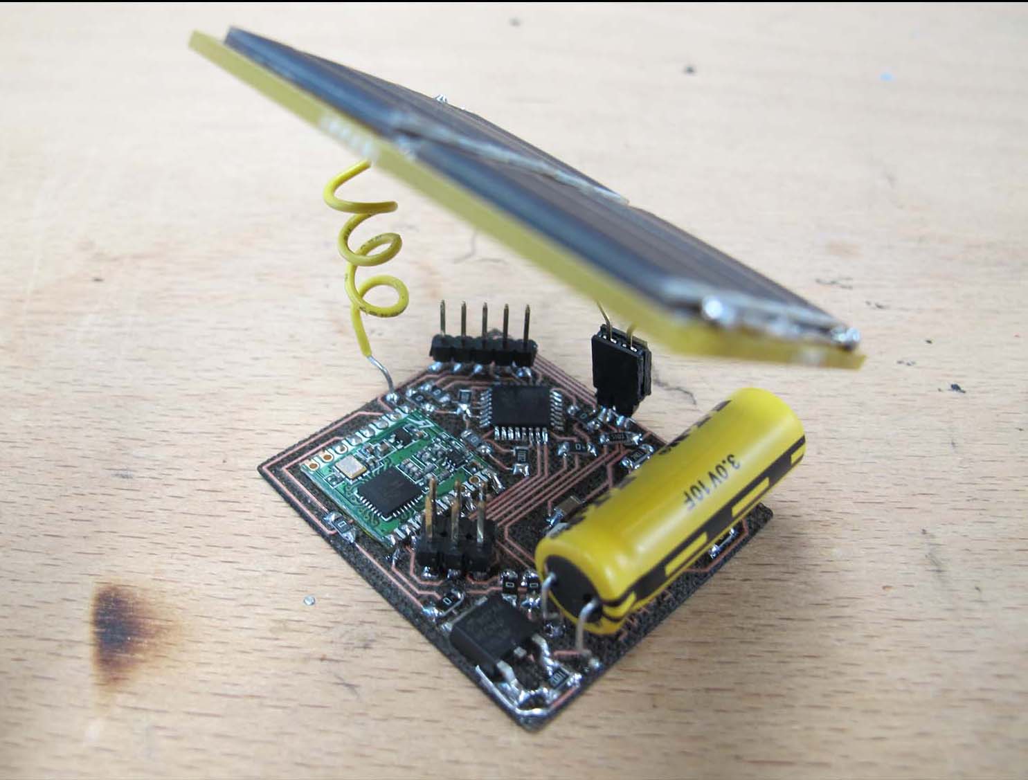
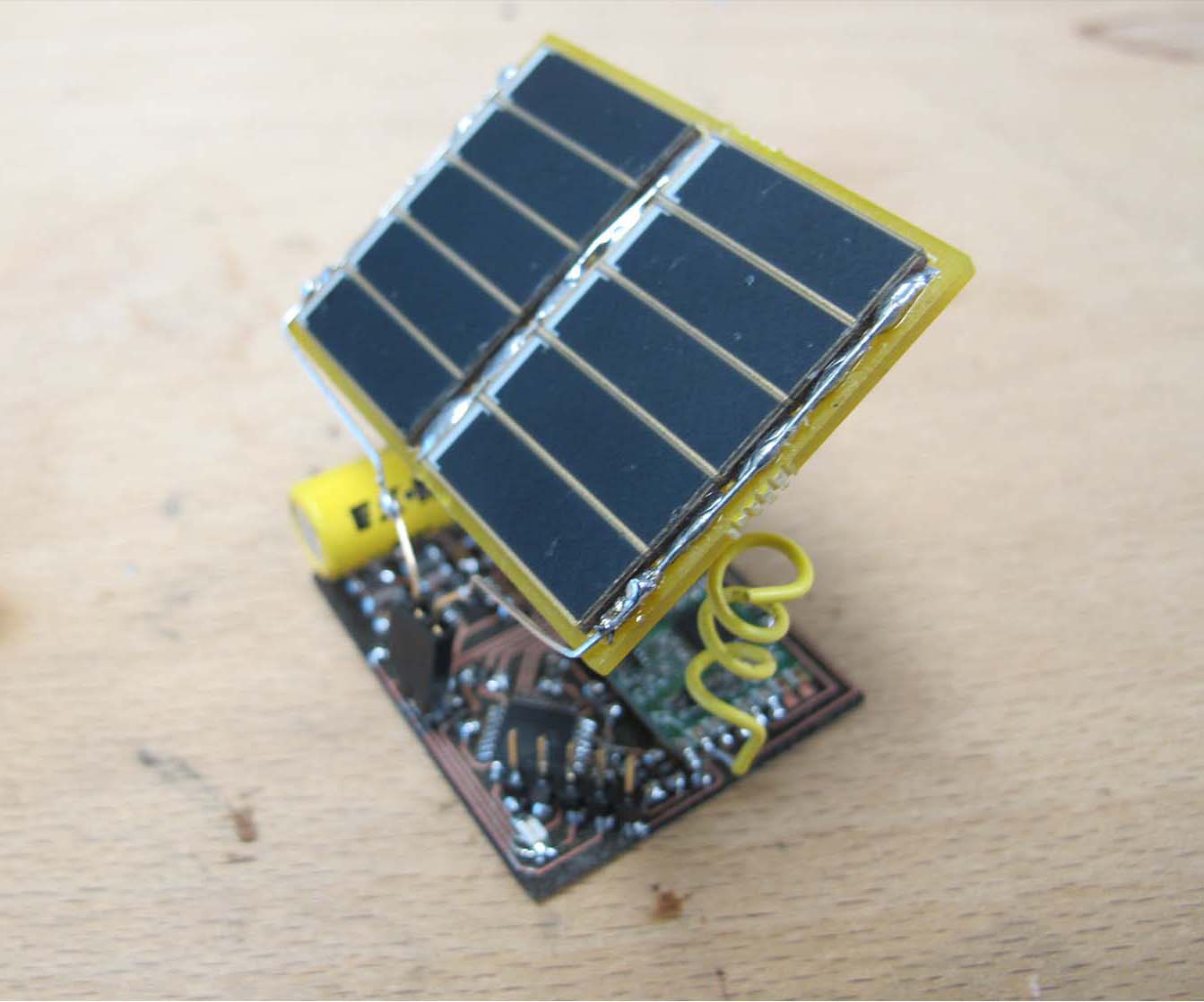
This solar-powered design uses the LT3105 energy harvester along with a supercap and the RFM69 module and high effeciency solar cells. Once it is charged it will send out temperature readings via RF to a receiver connected to a computer until it runs out of juice at which point it will put the microchip to sleep and wait for the super cap to recharge. It has impressive range and charges fast in good light.
I originally designed this as a workshop for Fab15 Egypt but the organizers had difficulty ordering the parts and so it never saw the light of day, pun intended. I picked the project back up and tried to document it well this time.
I’m using two RFM69HCWs : https://www.hoperf.com/modules/rf_transceiver/RFM69HCW.html
Here’s what it looks from the PC side:
And here are the schematics and board views:

Here’s what I laser engraved on double sided PCB :


The backside has a DRV8833 motor driver in case the user wants to add motors to control the angle of the solar panel in two axes.
Individual assignment: RX Assembly Instructions

Here is the list of all the necessary components for the two boards

Here is step 1 for the RX board:

For the receiver, first install the absolute minimum to test that the microchip can be programmed with ICP and blink an LED:

Next we’re going to add what’s necessary to talk to the computer via UART and some more jumpers :

Finally we’re going to install the RF module after everything else works:

Individual assignment: TX Assembly Instructions


Once we’ve completed the RX board we’re going to start the TX board. Once again we do the bare minimum to test the programming of the microchip and the blinking of an LED.

Then we’re going to move to some programming:

Next we’re going to test with the RF module:

And now back to programming:

Now we add the energy harvesting circuitry including the solar panels and super capacitors:

And back to more programming:

For troubleshooting:


Individual assignment: Future Versions
Here is the next iteration of this board which will be potted in resin and could be attached outside theoretically:


Developement and Errata:
I first messed around with some RFM12s and Attiny2313s before moving to the RFM69s and Atmega328s:
Here is the code for one RFM12B taking an analog measurement and sending it to the other which is printing the result via USART to a serial port.
TX side:
/*
 * Atmega168 RFM12B TX rev.2.c
 *
 * Author : FablabDigiscope
 */

#include <avr/io.h>

/* RFM12B INTERFACE */
#define SCK 5 // SPI clock
#define SDO 4 // SPI Data output (RFM12B side)
#define SDI 3 // SPI Data input (RFM12B side)
#define CS 2 // SPI SS (chip select)
#define NIRQ 2 // (PORTD)

/* IO CONTROL */
#define HI(x) PORTB |= (1<<(x))
#define LO(x) PORTB &= ~(1<<(x))


/* LED */
#define LED 6
#define LED_OFF() PORTD &= ~(1<<LED)
#define LED_ON() PORTD |= (1<<LED)

void analogInit() {
    ADMUX |= (1 << REFS0); // AREF ref voltage connected to power
    // PC0 input select
    ADCSRA |= (1 << ADPS2) | (1 << ADPS0); // set clock to 32 divisions for 8MHz
    ADCSRA |= (1 << ADEN); /* enable ADC */


}

unsigned int analogRead() {
    uint16_t adcValue; //16 bit variable because the ADC on the Attiny84 is 10 bits.
    ADCSRA |= (1 << ADSC); /* start conversion */
    adcValue = ADC; /* store high byte into adcValue */
    return adcValue;
}


void portInit() {
    HI(CS);
    HI(SDI);
    LO(SCK);
    DDRB = (1<<CS) | (1<<SDI) | (1<<SCK);
    DDRD = (1<<LED);
}

unsigned int writeCmd(unsigned int cmd) {
    unsigned char i;
    unsigned int recv;
    recv = 0;
    LO(SCK);
    LO(CS);

    for(i=0; i<16; i++) {
        if(cmd&0x8000) HI(SDI); else LO(SDI);
        HI(SCK);
        recv<<=1;
        if( PINB&(1<<SDO) ) {
            recv|=0x0001;
        }
        LO(SCK);
        cmd<<=1;
    }
    HI(CS);
    return recv;
}

void rfInit() {
    writeCmd(0x80E7); //EL,EF,868band,12.0pF
    writeCmd(0x8239); //!er,!ebb,ET,ES,EX,!eb,!ew,DC
    writeCmd(0xA640); //frequency select
    writeCmd(0xC647); //4.8kbps
    writeCmd(0x94A0); //VDI,FAST,134kHz,0dBm,-103dBm
    writeCmd(0xC2AC); //AL,!ml,DIG,DQD4
    writeCmd(0xCA81); //FIFO8,SYNC,!ff,DR
    writeCmd(0xCED4); //SYNC=2DD4,AG
    writeCmd(0xC483); //@PWR,NO RSTRIC,!st,!fi,OE,EN
    writeCmd(0x9850); //!mp,90kHz,MAX OUT
    writeCmd(0xCC17); //OB1,ACOB0, LPX,Iddy,CDDIT,CBW0
    writeCmd(0xE000); //NOT USED
    writeCmd(0xC800); //NOT USED
    writeCmd(0xC040); //1.66MHz,2.2V
}


void rfSend(unsigned char data){
    while(PIND&(1<<NIRQ));
    writeCmd(0xB800 + data);
}


int main() {
    volatile unsigned int i,j;
    asm("cli");
    for(i=0;i<1000;i++)for(j=0;j<123;j++);
    portInit();
    analogInit();
    rfInit();
    while(1){
        LED_ON();
        writeCmd(0x0000);
        rfSend(0xAA); // PREAMBLE
        rfSend(0xAA);
        rfSend(0xAA);
        rfSend(0x2D); // SYNC
        rfSend(0xD4);
        for(i=0; i<16; i++) {
            rfSend(analogRead());
        }
        rfSend(0xAA); // DUMMY BYTES
        rfSend(0xAA);
        rfSend(0xAA);
        LED_OFF();
        for(i=0; i<10000; i++) // some not very
        for(j=0; j<123; j++); // sophisticated delay
    }
}
RX side:
/*
 * Atmega168 RFM12B rev.2 RX.c
 *
 * Author : FablabDigiscope
 */


#include <avr/io.h>

/* RFM12B INTERFACE */
#define SCK 5 // SPI clock
#define SDO 4 // SPI Data output (RFM12B side)
#define SDI 3 // SPI Data input (RFM12B side)
#define CS 2 // SPI SS (chip select)
#define NIRQ 2 // (PORTD)

/* IO CONTROL */
#define HI(x) PORTB |= (1<<(x))
#define LO(x) PORTB &= ~(1<<(x))


/* LED */
#define LED 6
#define LED_OFF() PORTD &= ~(1<<LED)
#define LED_ON() PORTD |= (1<<LED)

/* USART */
#define BAUDRATE 25 // 19200 at 8MHz

void portInit() {
    HI(CS);
    HI(SDI);
    LO(SCK);
    DDRB = (1<<CS) | (1<<SDI) | (1<<SCK);
    DDRD = (1<<LED);
}


unsigned int writeCmd(unsigned int cmd) {
    unsigned char i;
    unsigned int recv;
    recv = 0;
    LO(SCK);
    LO(CS);

    for(i=0; i<16; i++) {
        if(cmd&0x8000) HI(SDI); else LO(SDI);
        HI(SCK);
        recv<<=1;
        if( PINB&(1<<SDO) ) {
            recv|=0x0001;
        }
        LO(SCK);
        cmd<<=1;
    }
    HI(CS);
    return recv;
}

void rsInit(unsigned char baud) {
    UBRR0L = baud;
    UCSR0C = (1<<UCSZ00) | (1<<UCSZ01); // 8N1
    UCSR0B = (1<<RXEN0) | (1<<TXEN0); // enable tx and rx
}

void rsSend(unsigned char data) {
    while( !(UCSR0A & (1<<UDRE0)));
    UDR0 = data;
}


unsigned char rsRecv() {
    while( !(UCSR0A & (1<<RXC0)));
    return UDR0;
}

/*    FOR ATTINY 2313
void rsInit(unsigned char baud) {
    UBRRL = baud;
    UCSRC = (1<<UCSZ0) | (1<<UCSZ1); // 8N1
    UCSRB = (1<<RXEN) | (1<<TXEN); // enable tx and rx
}
void rsSend(unsigned char data) {
    while( !(UCSRA & (1<<UDRE)));
    UDR = data;
}
unsigned char rsRecv() {
    while( !(UCSRA & (1<<RXC)));
    return UDR;
}
 */

void rfInit() {
    writeCmd(0x80E7); //EL,EF,868band,12.0pF
    writeCmd(0x8299); //er,!ebb,ET,ES,EX,!eb (low batt detector disabled),!ew,DC (bug was here)
    writeCmd(0xA640); //freq select
    writeCmd(0xC647); //4.8kbps
    writeCmd(0x94A0); //VDI,FAST,134kHz,0dBm,-103dBm
    writeCmd(0xC2AC); //AL,!ml,DIG,DQD4
    writeCmd(0xCA81); //FIFO8,SYNC,!ff,DR (FIFO level = 8)
    writeCmd(0xCED4); //SYNC=2DD4;
    writeCmd(0xC483); //@PWR,NO RSTRIC,!st,!fi,OE,EN
    writeCmd(0x9850); //!mp,90kHz,MAX OUT
    writeCmd(0xCC17); //!OB1,!OB0, LPX,!ddy,DDIT,BW0
    writeCmd(0xE000); //NOT USE
    writeCmd(0xC800); //NOT USE
    writeCmd(0xC040); //1.66MHz,2.2V
}


void rfSend(unsigned char data){
    while(PIND&(1<<NIRQ));
    writeCmd(0xB800 + data);
}


unsigned char rfRecv() {
    unsigned int data;
    while(1) {
        data = writeCmd(0x0000); // I think I would add here responses to Status
        if ( (data&0x8000) ) {
            data = writeCmd(0xB000);
            return (data&0x00FF);
        }
    }
}
void FIFOReset() {
    writeCmd(0xCA81);
    writeCmd(0xCA83);
}

int main(void) {

    unsigned char data, i;
    LED_OFF();
    portInit();
    rfInit();
    rsInit(BAUDRATE);
    //analogInit();
    FIFOReset();
    while(1) {
        //waitForData();
    for (i=0; i<16; i++) {
        data = rfRecv();
        rsSend(data);
        }
        FIFOReset();
        LED_OFF();
    }
    return 0;
}
Here is me with a breadboarded earlier version:

Here is me testing the solar harvesting IC with the super caps:

-I used SDA and SCL for motor driving but they should have been kept for I2C sensor reading.
-can’t use XTAL in arduino software environment (PB6 and PB7)
-I should have picked up a LUX sensor which already has readily available libraries AND is in stock, such as the VEML7700
-Because soldering tiny components is difficult and not fun I am considering eliminating the compass from the project. If the user sets the device to point north on start up it can track itself knowing the rotation of the motors.
And this code uses both the compass and the lux sensor, sharing the same lines.
This is the Lux sensor I’m using:
https://www.adafruit.com/product/1980
And I’m getting the temperature (and received transmission power reading) from inside the RF69.
I’m also reading two photodiodes and turning two motors. The photodiodes are set up like so: https://electronics.stackexchange.com/questions/73732/how-to-use-sfh235-ir-photodiode-correctly
Errata: SDA and SCL switched on LTC3105 board. Also, the lux sensor I bought VEML6030 doesn’t work. -break out PGOOD to a pin for testing purposes
Other idea for a minimal version of this circuit with attiny84.
Same thing with Atmega328p (getting things to work software side with Attiny + RF69 is tough…)
I’m calling it the wasp (a 10F cap has some sting!). I like that it fits on one board, this solves the most challenging aspect of the last design – connecting a bunch of pins between two boards and dealing with the cubersome thickness that it has in the end. It has less functionality but it has the essential stuff and maybe the rest was not necessary in the end. It’s ready to be embed in resin and strapped to a tree outdoors!
Individual assignment: TX and RX Code
// TX CODE:
// RFM69HCW Example Sketch
// Send serial input characters from one RFM69 node to another
// Based on RFM69 library sample code by Felix Rusu
// http://LowPowerLab.com/contact
// Modified for RFM69HCW by Mike Grusin, 4/16

// This sketch will show you the basics of using an
// RFM69HCW radio module. SparkFun's part numbers are:
// 915MHz: https://www.sparkfun.com/products/12775
// 434MHz: https://www.sparkfun.com/products/12823

// See the hook-up guide for wiring instructions:
// https://learn.sparkfun.com/tutorials/rfm69hcw-hookup-guide

// Uses the RFM69 library by Felix Rusu, LowPowerLab.com
// Original library: https://www.github.com/lowpowerlab/rfm69
// SparkFun repository: https://github.com/sparkfun/RFM69HCW_Breakout

// Include the RFM69 and SPI libraries:
#include <SPI.h>
#include <avr/wdt.h>
#include <RFM69.h>
#include <avr/sleep.h>


// Addresses for this node. CHANGE THESE FOR EACH NODE!

#define NETWORKID     0   // Must be the same for all nodes
#define MYNODEID      2   // My node ID
#define TONODEID      1   // Destination node ID

// RFM69 frequency, uncomment the frequency of your module:

//#define FREQUENCY   RF69_433MHZ
#define FREQUENCY     RF69_915MHZ

// AES encryption (or not):

#define ENCRYPTKEY    "TOPSECRETPASSWRD" // Use the same 16-byte key on all nodes

// Use ACKnowledge when sending messages (or not):

#define USEACK        true // Request ACKs or not

// Packet sent/received indicator LED (optional):

#define LED          A3 // LED positive pin

#define PGOOD         3 // PGOOD


#define MOSFET      9//


// Create a library object for our RFM69HCW module:


int level;

RFM69 radio;


void setup()
{
  // Open a serial port so we can send keystrokes to the module:


    pinMode(LED,OUTPUT);
    digitalWrite(LED,LOW);
    pinMode(MOSFET,OUTPUT); //mosfet
    pinMode(PGOOD, INPUT); // PGOOD

}

void loop()
{

wdt_enable(WDTO_8S);

level = digitalRead(PGOOD);

if(level == HIGH)

{

 char Tstr[10];


  digitalWrite(MOSFET, HIGH); // turn on MOSFET
  delay(100);
  radio.initialize(FREQUENCY, MYNODEID, NETWORKID);
  radio.setHighPower(); // Always use this for RFM69HCW

  // Turn on encryption if desired:

    radio.encrypt(ENCRYPTKEY);

   double T = radio.readTemperature();


  char buffer[50];


  dtostrf(T, 3,3, Tstr);


  static int sendlength = strlen(buffer);


sprintf(buffer, " T:%s", Tstr);


      radio.sendWithRetry(TONODEID, buffer, sendlength);


      Blink(LED,100);

}

else
{
sleep();
}

}


void Blink(byte PIN, int DELAY_MS)
// Blink an LED for a given number of ms
{
  digitalWrite(PIN,HIGH);
  delay(DELAY_MS);
  digitalWrite(PIN,LOW);
}

void sleep(void)
{
  digitalWrite(MOSFET, LOW); // turn on MOSFET
  set_sleep_mode(SLEEP_MODE_PWR_DOWN); //select PWR DOWN, the most power savings
  sleep_enable(); //set  SE bit
  sei(); // enable global interrupts
  sleep_cpu(); //actually sleep
  sleep_disable(); //code reaches this point after interrupt
}
++++++++++++++++++++++++++++++++++++++++++++++++++++++++++++++++++++++++++++++++++++++++++++++++++++++++++++++++++++++++++++++
And here is the RX code:
// RX CODE
// RFM69HCW Example Sketch
// Send serial input characters from one RFM69 node to another
// Based on RFM69 library sample code by Felix Rusu
// http://LowPowerLab.com/contact
// Modified for RFM69HCW by Mike Grusin, 4/16

// This sketch will show you the basics of using an
// RFM69HCW radio module. SparkFun's part numbers are:
// 915MHz: https://www.sparkfun.com/products/12775
// 434MHz: https://www.sparkfun.com/products/12823

// See the hook-up guide for wiring instructions:
// https://learn.sparkfun.com/tutorials/rfm69hcw-hookup-guide

// Uses the RFM69 library by Felix Rusu, LowPowerLab.com
// Original library: https://www.github.com/lowpowerlab/rfm69
// SparkFun repository: https://github.com/sparkfun/RFM69HCW_Breakout

// Include the RFM69 and SPI libraries:

#include <RFM69.h>
#include <SPI.h>

// Addresses for this node. CHANGE THESE FOR EACH NODE!

#define NETWORKID     0   // Must be the same for all nodes
#define MYNODEID      2   // My node ID
#define TONODEID      1   // Destination node ID

// RFM69 frequency, uncomment the frequency of your module:

//#define FREQUENCY   RF69_433MHZ
#define FREQUENCY     RF69_915MHZ

// AES encryption (or not):

#define ENCRYPT       true // Set to "true" to use encryption
#define ENCRYPTKEY    "TOPSECRETPASSWRD" // Use the same 16-byte key on all nodes

// Use ACKnowledge when sending messages (or not):

#define USEACK        true // Request ACKs or not

// Packet sent/received indicator LED (optional):

#define LED           14 // LED positive pin


// Create a library object for our RFM69HCW module:

RFM69 radio;

void setup()
{
  // Open a serial port so we can send keystrokes to the module:

  Serial.begin(9600);
  Serial.print("Node ");
  Serial.print(MYNODEID,DEC);
  Serial.println(" ready");

  // Set up the indicator LED (optional):

  pinMode(LED,OUTPUT);
  pinMode(7,OUTPUT);
  digitalWrite(LED,LOW);


  // Initialize the RFM69HCW:

  radio.initialize(FREQUENCY, MYNODEID, NETWORKID);
  radio.setHighPower(); // Always use this for RFM69HCW

  // Turn on encryption if desired:

  if (ENCRYPT)
    radio.encrypt(ENCRYPTKEY);
}

void loop()
{


  static char sendbuffer[62];
  static int sendlength = 0;


  // RECEIVING

  // In this section, we'll check with the RFM69HCW to see
  // if it has received any packets:


if (radio.receiveDone()) // Got one!
  {
    // Print out the information:

    Serial.print("received from node ");
    Serial.print(radio.SENDERID, DEC);
    Serial.print(", message [");

    // The actual message is contained in the DATA array,
    // and is DATALEN bytes in size:

    for (byte i = 0; i < radio.DATALEN; i++)
      Serial.print((char)radio.DATA[i]);

    // RSSI is the "Receive Signal Strength Indicator",
    // smaller numbers mean higher power.

    Serial.print("], RSSI ");
    Serial.println(radio.RSSI);

    // Send an ACK if requested.
    // (You don't need this code if you're not using ACKs.)

    if (radio.ACKRequested())
    {
      radio.sendACK();
      Serial.println("ACK sent");
    }
    Blink(LED,10);
  }
}


void Blink(byte PIN, int DELAY_MS)
// Blink an LED for a given number of ms
{
  digitalWrite(PIN,HIGH);
  delay(DELAY_MS);
  digitalWrite(PIN,LOW);
}
+++++++++++++++++++++++++++++++++++++++++++++++++++++++++++++++++++++++++++++++++++++++++++++++++++++++++++++++++++++++++++++++++
GROUP PROJECT : I2C
We sent a message from Ambroise’s attiny board, connected to a Distance sensor, to Quentin’s board, which is an atmega 328 connected to a LCD display. They are communicating through I2C connection. SDA and SCL pins are connected and the appropriate codes are uploaded onto the respective boards.
INDIVIDUAL PROJECT : I2C
I2C (a.k.a. TWI, 2 Wire Interface) is a communication protocol that can allow your “master” microcontroller to speak to up 120+ “slave” devices. The protocol requires only two wires, one for data (SDA) and the other for the clock (SCL). Each device is connected to the same two wires but each also has a unique 7 bit address so it knows when the master is communicating with it. Data can go both ways, from the Master to the Slave but also from the Slave to the Master.

Data is read when the SCL goes high (a.k.a. when SCL is “released”, i.e. not pulled down, and allowed to be pulled up by the 4.7k resistors) and data can be changed while SCL is low.
After the Master sends the seven bit address of the slave it wishes to speak with, it sends Read (1) or Write (0) bit. The slave then sends an Acknowledge (ACK) – 0 / Not Acknowledge (NACK) – 1 bit. This means that each communication portion is 9 bits in total.

If the master wants to write to the slave the next communication portion will be 8 bits of data followed by an ACK/NACK from the Slave.

Pins 27 (Data) and 28 (Clock) for the Atmega 168 / 328 are the pertinent pins.
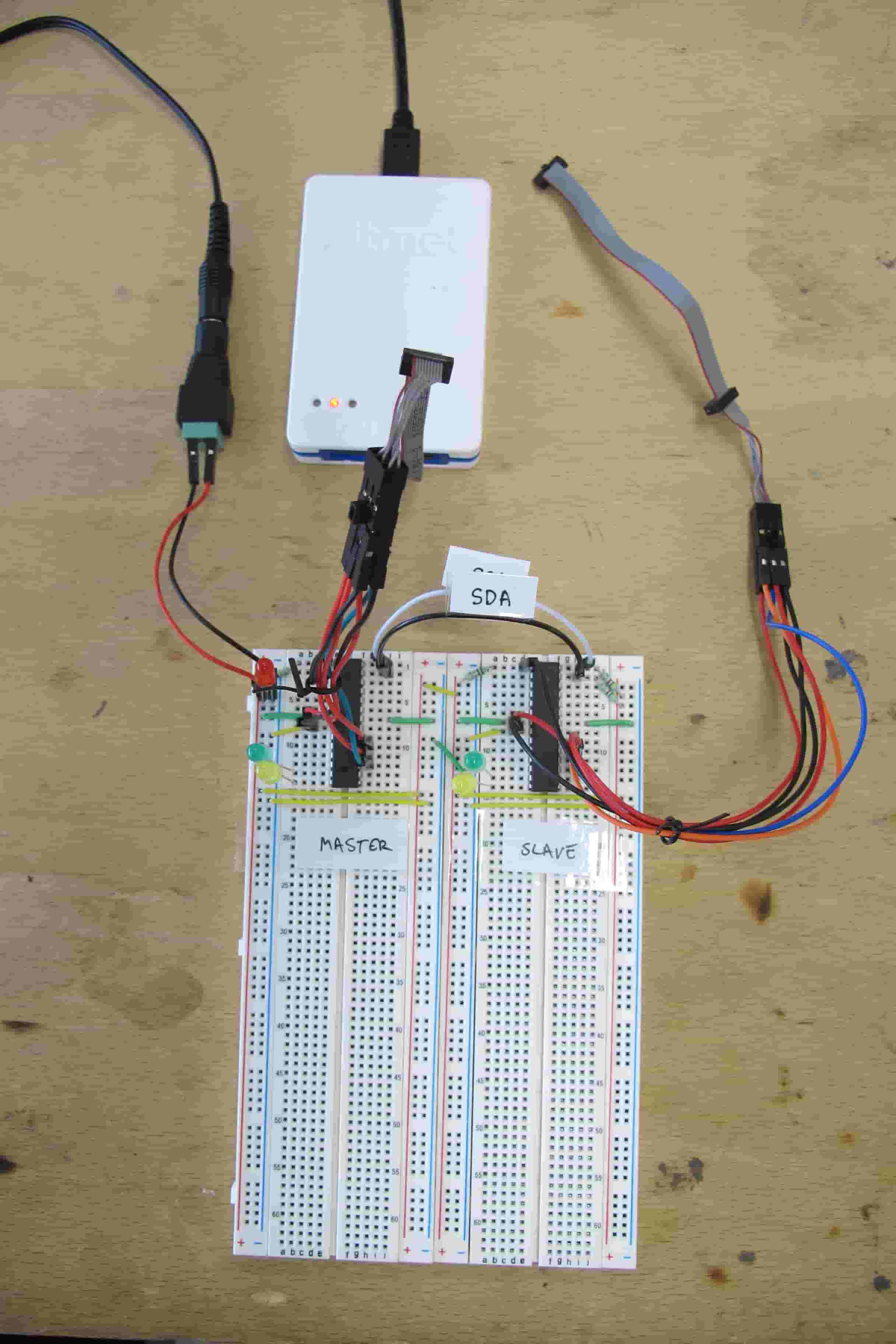
Here is my breadboard set up for testing two Atmega168 with I2C. I have I2C cables which makes changing the sender and receiver code with the atmelICE less of a chore. I first wanted to use attiny but then learned that the Attiny family does not have the same level of I2C support as the Atmega family. The Attiny Universal Serial Interface (USI) can be used with I2C but the user has to do more work in software and can rely on fewer hardware peripherals to help with the job.
While there are many examples of Atmega master codes, I found it hard to find examples of Atmega slave code. Most often we use I2C to speak with a sensor which is the slave. I was interested in microchip to microchip communication and so decided to get two atmegas talking to one another. Elliot Williams’ Make: AVR Programming was a great resource for making the code.
For the breadboard set up I have a power LED and a yellow LED for successfully sending the slave address and a green LED for successfully sending the data. On the RX side I have a yellow LED for successfully receiving the slave address and a green LED for successfully receiving the data. I have two 4.7K pull-up resistors for the SDA and SCL lines and a 10K pullup on reset. It’s powered with a 5V adapter.

Digiscope Fablab has a 100MHz 4 channel Agilent DSO-X 2014A Oscilloscope with a demo version of the I2C, SPI and USART decoder software. To get the oscilloscope into the right mode I selected the Serial button (on the right side), select the type of protocol to decode (I2C) and then the Lister Button to show the decoded data above the signals. To set the trigger press trigger and select Serial (I2C) from the Trigger Type menu and then select to Trigger on Start. Put the oscilloscope into Single Run Control mode and then connect the circuit to power and hope it triggers. If you are triggering on the power spike that occurs when you plug in the circuit, try adding a delay at the start of the code so you can comfortably do the plugging in, then setting into Single Run Mode and waiting for the trigger.
I have my signals in 1V per square and am between 200ms and 20ms per time division. I use the smaller horizontal knob to move the recorded signal side to side.

In these first examples I had difficulty getting past the first part of the I2C communication of sending the slave address (7 bits) + the Read (1) or Write (0) bit.


Eventually I could get communication going, including reading bytes sent from the slave and multiple starts during a conversation. The issue turned out to be strange, if I set both the TWEN and TWEA bits of the TWCR in the same line, I never got past the first slave address stage of the I2C conversation. When I set then in different lines everything works smoothly. Still not sure why this is the case!
Here is the code I developed (for Master):
/*
 * I2C atmega168.c
 *
 * Author : FablabDigiscope

 4.7K pull up resistors on SDA and SCL
 10K pull up on reset

 2x atmega168

 */

#include <avr/io.h>
#include <util/delay.h>

#define F_CPU                8000000
#define SLAVE_ADDRESS_W      0b10010000/* 0x90: 7 bit slave address + R(1)/W(0) bit (then slave responds with ACK(0)/NACK(1) bit) */
#define SLAVE_ADDRESS_R      0b10010001/* 0x91: 7 bit slave address + R(1)/W(0) bit (then slave responds with ACK(0)/NACK(1) bit) */

#define SLAVE2_ADDRESS_W     0b10110000/* 0x90: 7 bit slave address + R(1)/W(0) bit (then slave responds with ACK(0)/NACK(1) bit) */
#define SLAVE2_ADDRESS_R     0b10110001/* 0xB1*/

#define DATA_TO_SEND         0b00000000/* 0x00 */
#define DATA_TO_SEND_2       0b11111111/* 0xFF */
#define DATA_TO_RECEIVE      0b10101010/* OxAA */
#define DATA_TO_RECEIVE_2    0b01010101/* Ox55 */

//function prototypes
void i2cInit(void);
void i2cStart(void);
void i2cWaitForComplete1(void);
void i2Send(uint8_t data); //data sent same way as address
void i2cWaitForComplete2(void);
                            //data sent same way as address
void i2cWaitForComplete3(void);
void i2cStop(void);
uint8_t  i2cRead(void);


int main(void)
{
    DDRB = 0b11111111; /* green LED for all good */
    DDRD = 0b11111111; /* yellow LED for all good, red for errors */

    i2cInit();

    while (1)
    {
        _delay_ms(1000);


        i2cStart();
        i2cWaitForComplete1();
        i2Send(SLAVE_ADDRESS_W);
        i2cWaitForComplete2();
        i2Send(DATA_TO_SEND);
        i2cWaitForComplete3();

                i2cStart();
                i2cWaitForComplete1();
                i2Send(SLAVE_ADDRESS_R);
                i2cWaitForComplete2();

                if (DATA_TO_RECEIVE == i2cRead())
                {
                    PORTD |= (1<<PD7); // turn on green led
                }

                                i2cStart();
                                i2cWaitForComplete1();
                                i2Send(SLAVE2_ADDRESS_W);
                                i2cWaitForComplete2();
                                i2Send(DATA_TO_SEND_2);
                                i2cWaitForComplete3();
                                i2cStop();

                                i2cStart();
                                i2cWaitForComplete1();
                                i2Send(SLAVE2_ADDRESS_R);
                                i2cWaitForComplete2();

                                if (DATA_TO_RECEIVE_2 == i2cRead())
                                {
                                    PORTD |= (1<<PD6); // turn on green led
                                }


    }
}


//function declarations

void i2cInit(void)
{
        TWBR = 32; /*set bit rate to 100kHz*/
        TWCR |= (1 << TWEN); /*enable I2C*/
}

void i2cStart(void)
        {
            /*

        I2C start
                       _____________
                      |             |
        SCL: _________|             |_____

                  __________
                 |          |
        SDA: ____|          |_____________

        */

        TWCR = (1 << TWEN) | (1 << TWINT) | (1 << TWSTA); /*set to enable the 2-wire serial interface ; clear the TWINT flag ; TWSTA written to one to transmit a START condition */

        }

void i2cWaitForComplete1(void)
    {

    /*I2C wait for complete*/
    while (!(TWCR & (1<<TWINT)));

    if ((TWSR & 0xF8) != 0x08) // 0x08 = A START condition has been transmitted
    {
        PORTD |= (1 << PD0);    //ERROR
    }

    if ((TWSR & 0xF8) == 0x00)
    {
        PORTD |= (1 << PD5);    //ERROR  Bus error
    }
    }

void i2Send(uint8_t data)
{
        /*
    I2C send data


             ___     ___     ___     ___     ___     ___     ___     ___     ___
            |   |   |   |   |   |   |   |   |   |   |   |   |   |   |   |   |   |
    SCL: ___|   |___|   |___|   |___|   |___|   |___|   |___|   |___|   |___|   |___


    SDA:     D8      D7       D6     D5       D4      D3      D2     D1       D0

    */

    TWDR = data; /*send data - do this BEFORE setting TWINT*/
    TWCR = (1 << TWINT) | (1 << TWEN);

}

void i2cWaitForComplete2(void)
{

/*I2C wait for complete*/
while (!(TWCR & (1<<TWINT)));

if ((TWSR & 0xF8) != 0x18) // 0x18 = SLA+W has been transmitted; ACK has been received
{
    if ((TWSR & 0xF8) == 0x20)
    {
        PORTD |= (1 << PD1);    //ERROR  Not acknowledge received after the slave address
    }
    if ((TWSR & 0xF8) == 0x38)
    {
        PORTD |= (1 << PD2);    //ERROR  Arbitration lost in slave address or data byte
    }
    if((TWSR & 0xF8) == 0x68)
    {
        PORTD |= (1 << PD3);    //ERROR  Arbitration lost and addressed as slave
    }
    if ((TWSR & 0xF8) == 0x00)
    {
        PORTD |= (1 << PD5);    //ERROR  Bus error
    }
}
}
void i2cWaitForComplete3(void)
{

    /*I2C wait for complete*/

    while (!(TWCR & (1<<TWINT)));

    if ((TWSR & 0xF8) != 0x28) //0x28 = Data byte has been transmitted; ACK has been received
    {
        if ((TWSR & 0xF8) == 0x30)
        {
            PORTD |= (1 << PD4);    //ERROR Not acknowledge received after a data byte
        }
        if ((TWSR & 0xF8) == 0x00)
        {
            PORTD |= (1 << PD5);    //ERROR  Bus error
        }
    }
}

void i2cStop(void)
{
    /*

    I2C stop

                   _____________
                  |             |
    SCL: _________|             |_____

                      ________________
                     |
    SDA: ____________|

    */

    TWCR = (1 << TWINT) | (1 << TWEN) | (1 << TWSTO);
    //_delay_us(10);
}

uint8_t i2cRead(void)
{

    TWCR = (1 << TWINT) | (1 << TWEN); //read with no ack
    while (!(TWCR & (1<<TWINT)));
    return (TWDR);
}
++++++++++++++++++++++++++++++++++++++++++++++++++++++++++++++++++++++++++++++++++++++++++++++++++++++++++++++
Here is the code I developed (for Slave):
/*
 * atmega I2C slave.c
 *
 * Author : FablabDigiscope
 */

#include <avr/io.h>


#define F_CPU                8000000
#define SLAVE_ADDRESS_W      0b10010000/* 0x90: 7 bit slave address + R(1)/W(0) bit (then slave responds with ACK(0)/NACK(1) bit) */
#define SLAVE_ADDRESS_R      0b10010001/* 0x91: 7 bit slave address + R(1)/W(0) bit (then slave responds with ACK(0)/NACK(1) bit) */

#define SLAVE2_ADDRESS_W     0b10110000/* 0x90: 7 bit slave address + R(1)/W(0) bit (then slave responds with ACK(0)/NACK(1) bit) */
#define SLAVE2_ADDRESS_R     0b10110001/* 0xB1*/

#define DATA_TO_SEND         0b00000000/* 0x00 */
#define DATA_TO_SEND_2       0b11111111/* 0xFF */
#define DATA_TO_RECEIVE      0b10101010/* OxAA */
#define DATA_TO_RECEIVE_2    0b01010101/* Ox55 */

int main(void)
{
    DDRB = 0b11111111;
    DDRD = 0b11111111;

    while (1)
    {


    TWAR = SLAVE2_ADDRESS_W;    // Fill slave address in TWAR register
    TWCR |= (1 << TWEN);  // I2c enable; MYSTERY: if I set these two bits at the same time nothing works.
    TWCR |= (1 << TWEA);  // enable acknowledge (automatically generates ACK)

    while (!(TWCR & (1<<TWINT))); // interrupt flag which tells slave when it's address is being called

        if((TWSR & 0xF8) == 0x60) // SLA+W received, ACK'd
        {
            PORTB |= (1<<PB0);
        }


        if((TWSR & 0xF8) == 0x80) // Data received, ACK'd...
        {
            if (TWDR == DATA_TO_SEND_2) // ...and data matches what was send
                {
                PORTD |= (1<<PD7);
                }
        }


    while (!(TWCR & (1<<TWINT))); // interrupt flag which tells slave when it's address is being called

            if((TWSR & 0xF8) == 0xA8) // Own SLA+R has been received; ACK has been returned
            {
                TWDR = DATA_TO_RECEIVE_2;
            }

        while (!(TWCR & (1<<TWINT))); // interrupt flag which tells slave when it's address is being called

        if((TWSR & 0xF8) == 0xC0) // Data byte in TWDR has been transmitted; NOT ACK has been received
        {
            PORTD |= (1<<PD6);
        }

//      if((TWSR & 0xF8) == 0xB8) // Data byte in TWDR has been transmitted; ACK has been received
//          PORTD |= (1<<PD6);
//      }

//      if((TWSR & 0xF8) == 0xC8) // Own SLA+R has been received; ACK has been returned
//      {
//          PORTD |= (1<<PD6);
//      }
//

    }
}

In the end there were so many issues that I had added LEDs for each different error type with little notes describing the error in question. This experience also convinced me that it would help to have a dedicated I2C board for first-timers.