7. Computer controlled machining
This week’s assignment:
group assignment: do your lab’s safety training test runout, alignment, speeds, feeds, materials, and toolpaths for your machine
individual assignment: make (design+mill+assemble) something big (~meter-scale)
++++++++++++++++++++++++++++++++++++++++++++++++++++++++++++++++++++++++++++++++++++++++++++++++++++++++++++++++++++++++++++
For the SCARA robot:
Here are my 2D files:
And the Rhino 3d file:
For the electronic instrument organizer:
2D:
3D:
Group Assignment
Here is a slide show I made as a Shopbot + V Carve primer for us this week:
I am using a 1/4” Onsrud 57-910 https://www.onsrud.com/Products/57910.asp
Individual Assignment: SCARA robot design + 3D printed prototype
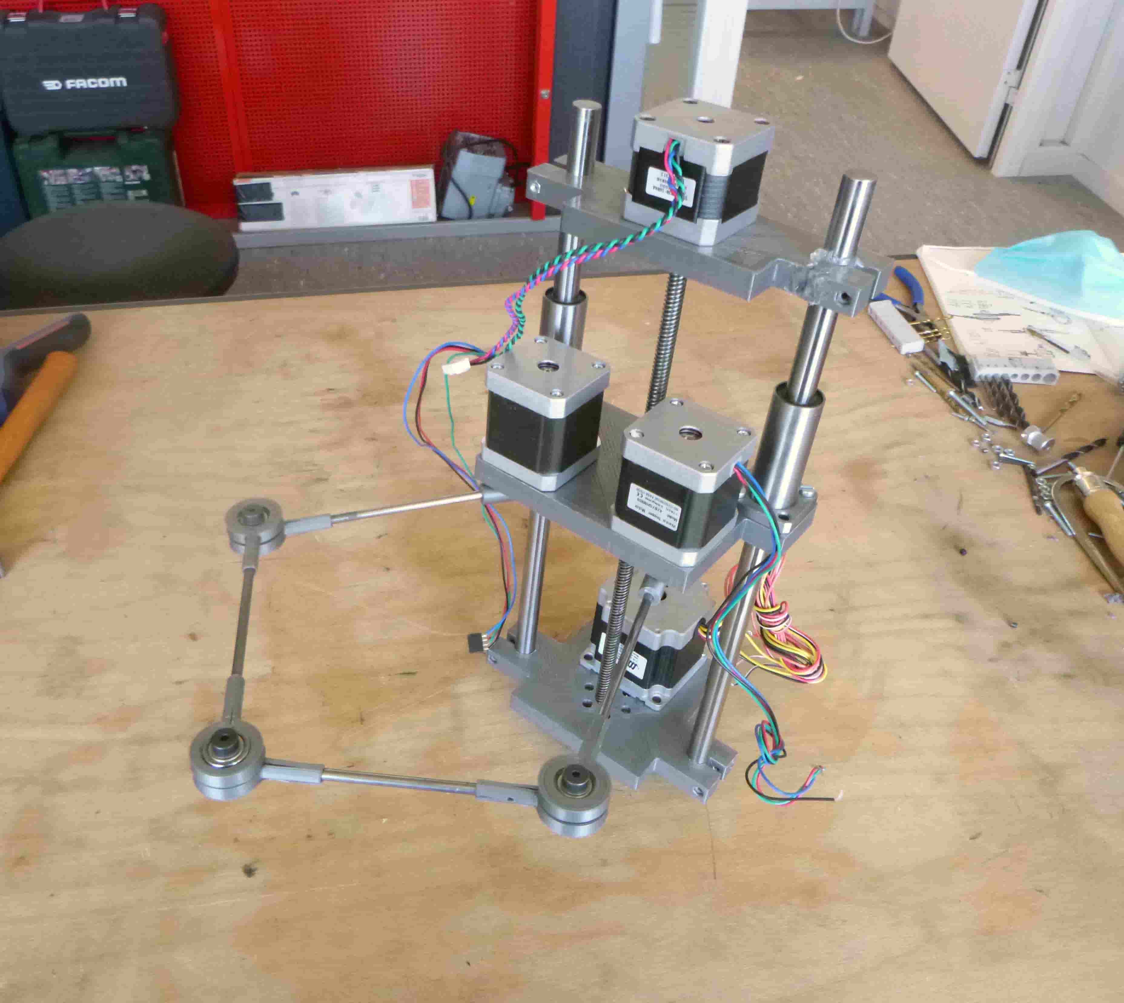
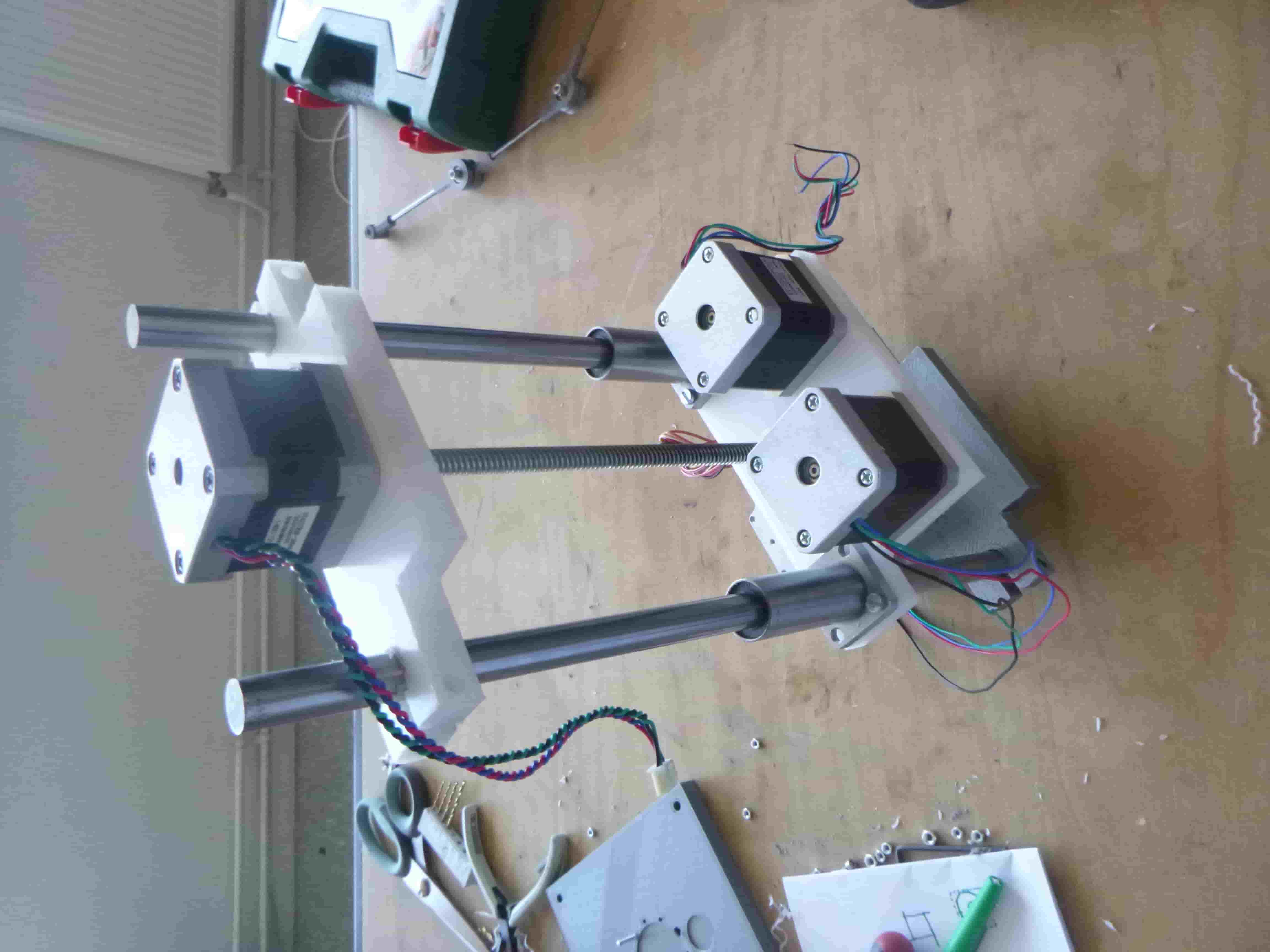
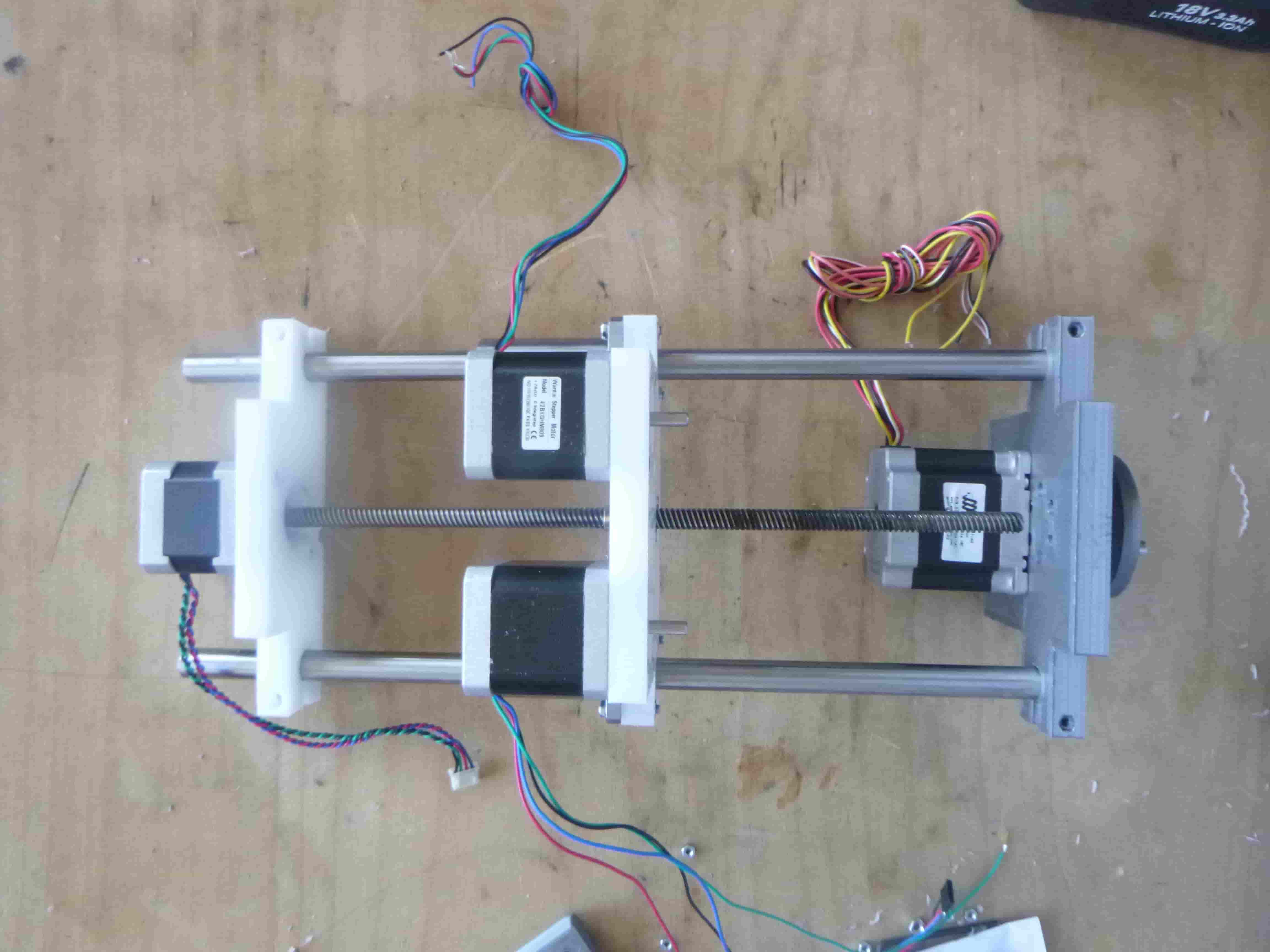
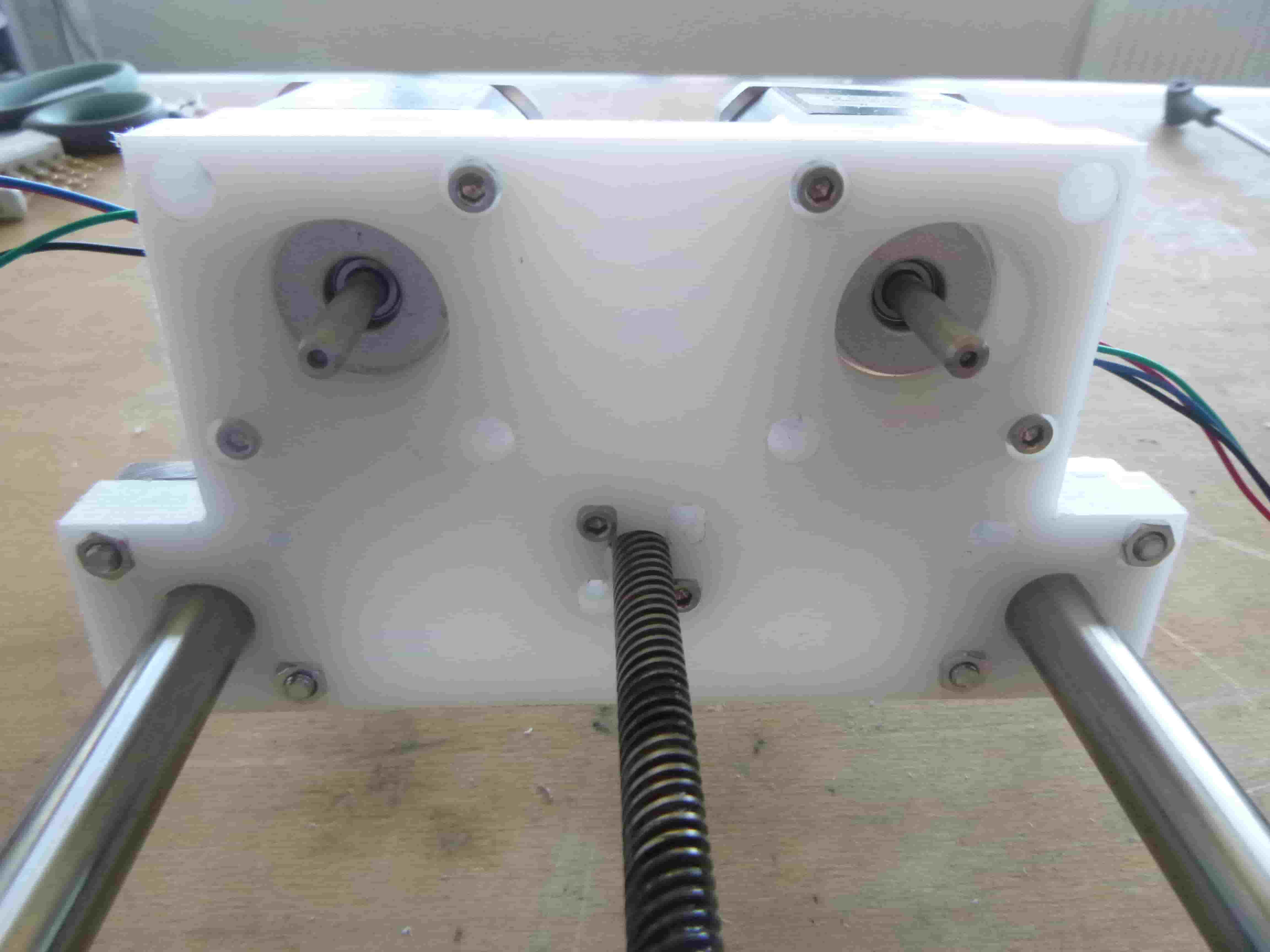
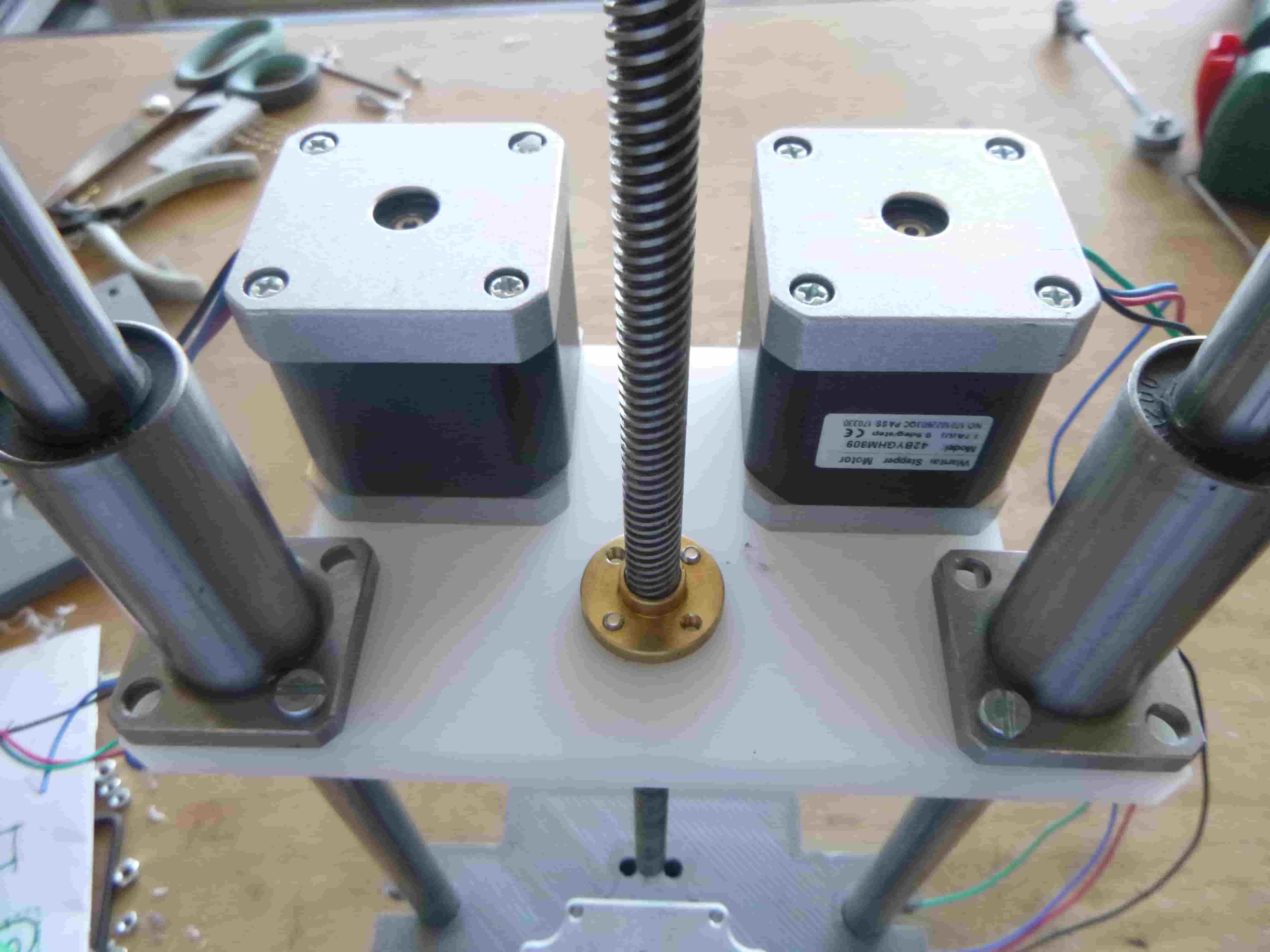
This is a 5 bar parallel SCARA robot I designed first to be 3D printed and then to be milled from HDPE to demonstrate my ability to CNC machine something.
The most complex part is the bearing assembly at the base.
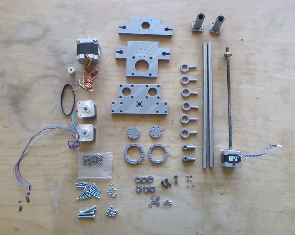
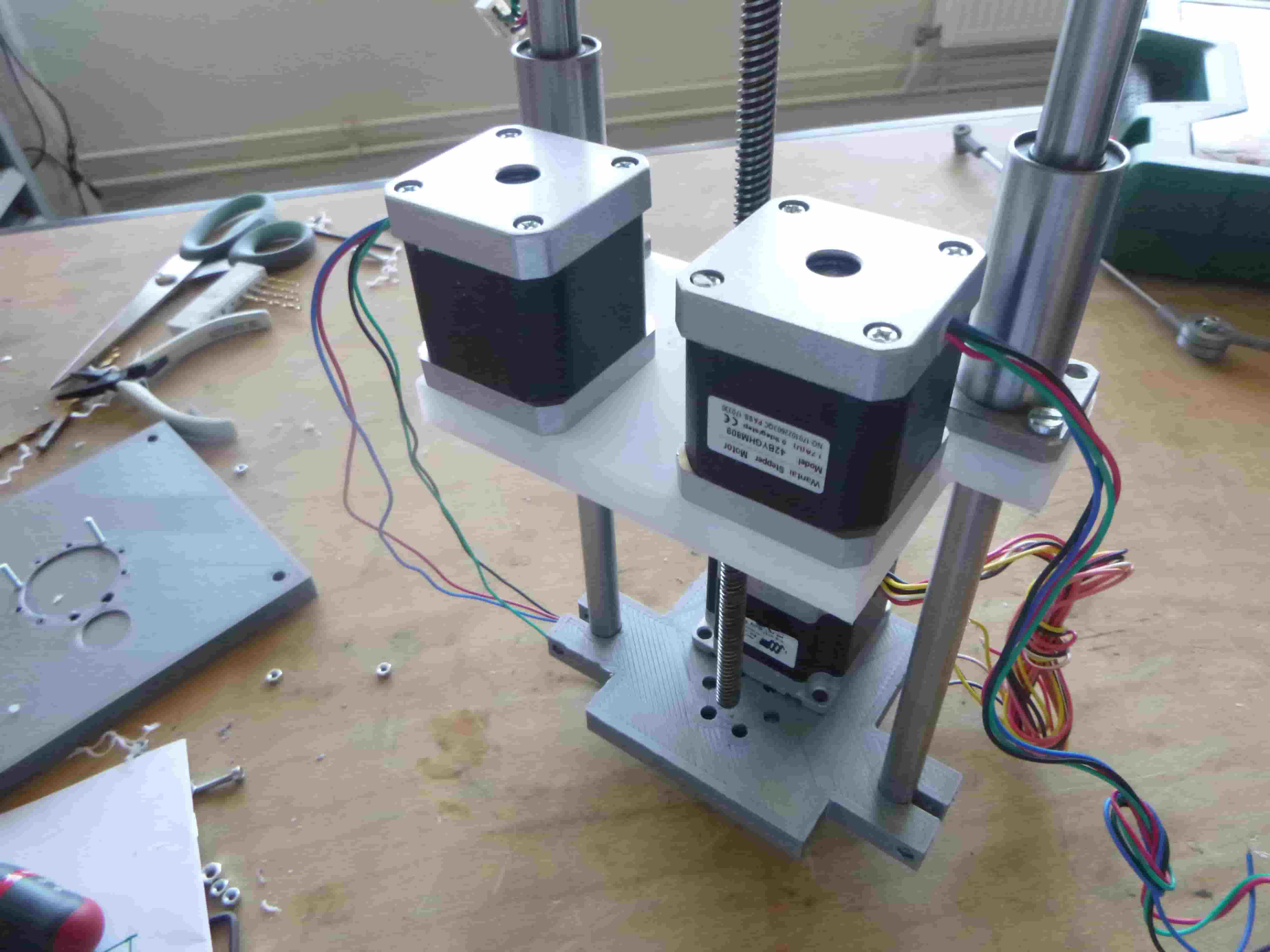
I am using parts from an old Makerbot (the linear rails, belt, leadscrew and nut) as well as stepper motors we had lying around for the machine week along with some steel rod from the basement.
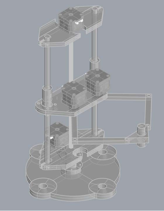
Here are some of the 3D designs I experimented with beforehand:
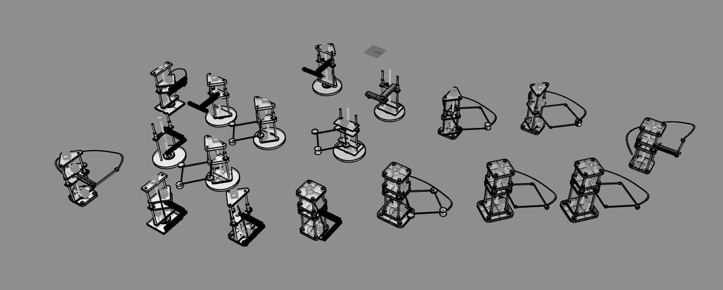
I liked the triangular shape and emphasized it here:
Flipped around:
With motors in front:
With an arm made of extruded aluminum:
Quite close to the final design using a kind of lozenge design:
A different option made up of planar elements to make a blocky arm:
Here I experimented with a kind of lozenge design:
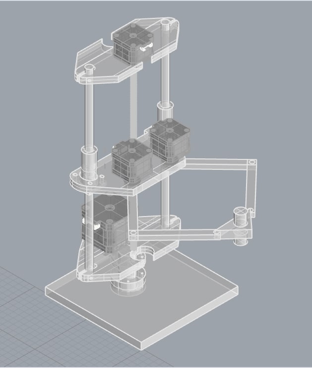
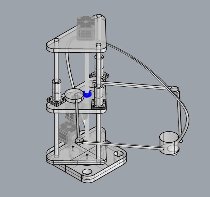
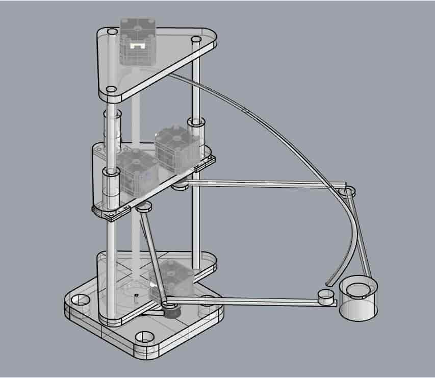
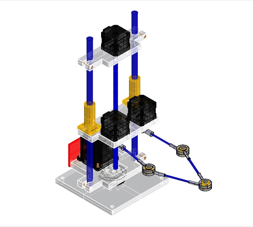
Here is the final design I settled on:
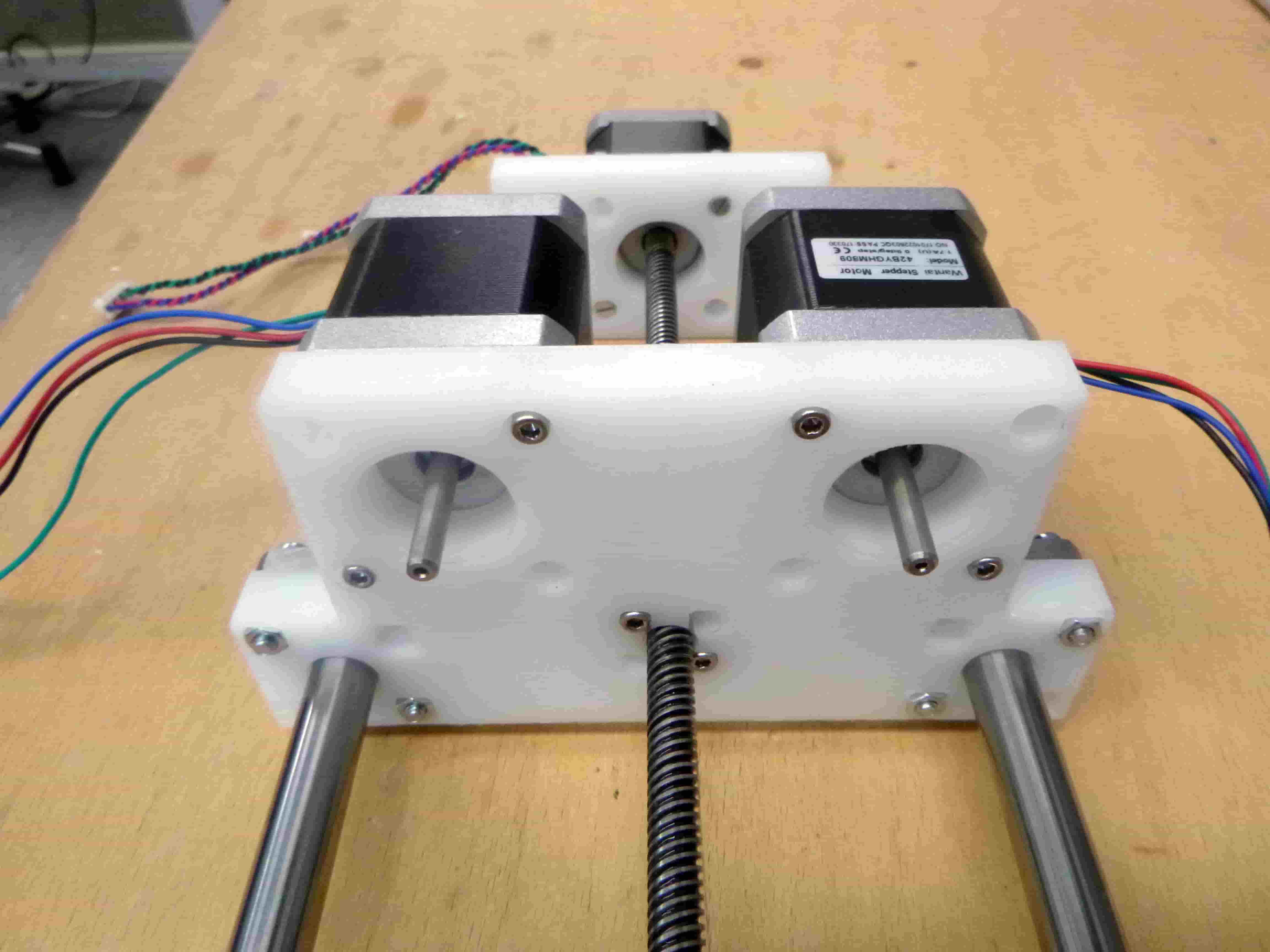
And here it is again but with all the hardware:
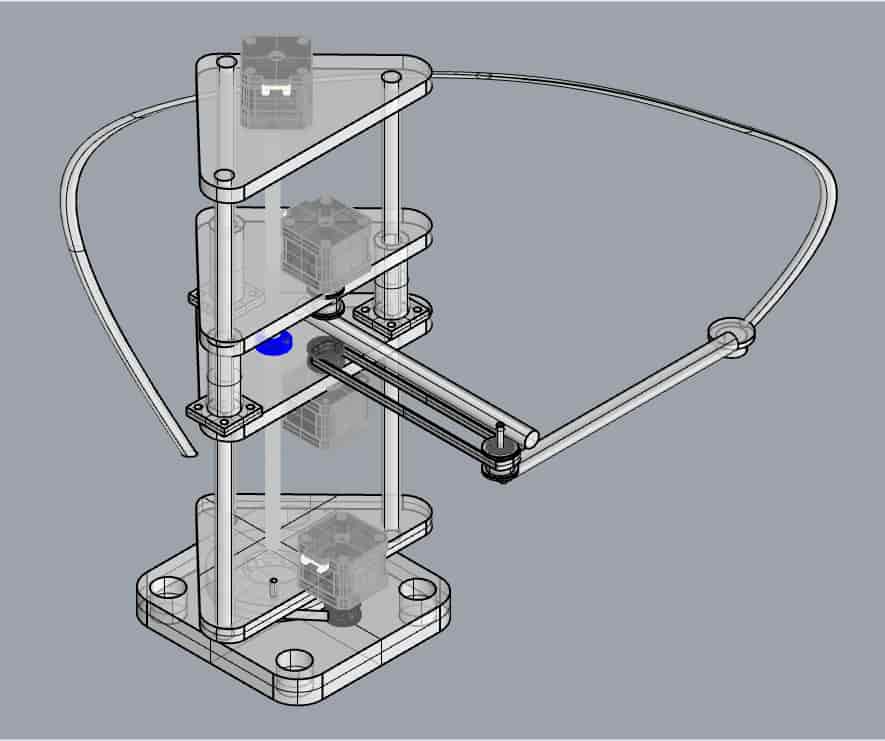
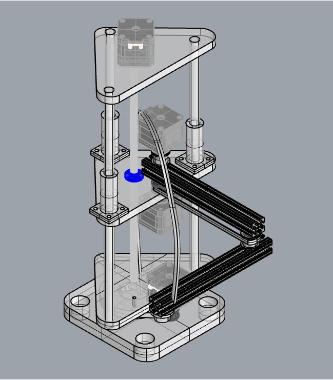
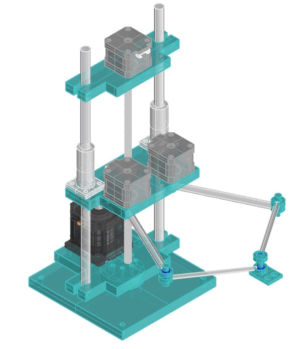
Here is the original 3D printed version of the machine with all the hardware necessary:
Assembled minus the base plate:
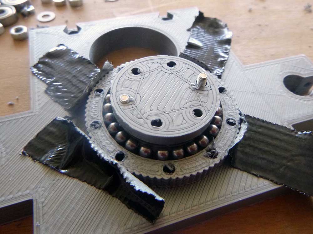
Here was the design I eventually built for the bearing. I was not able to make a CNC milled version of this.
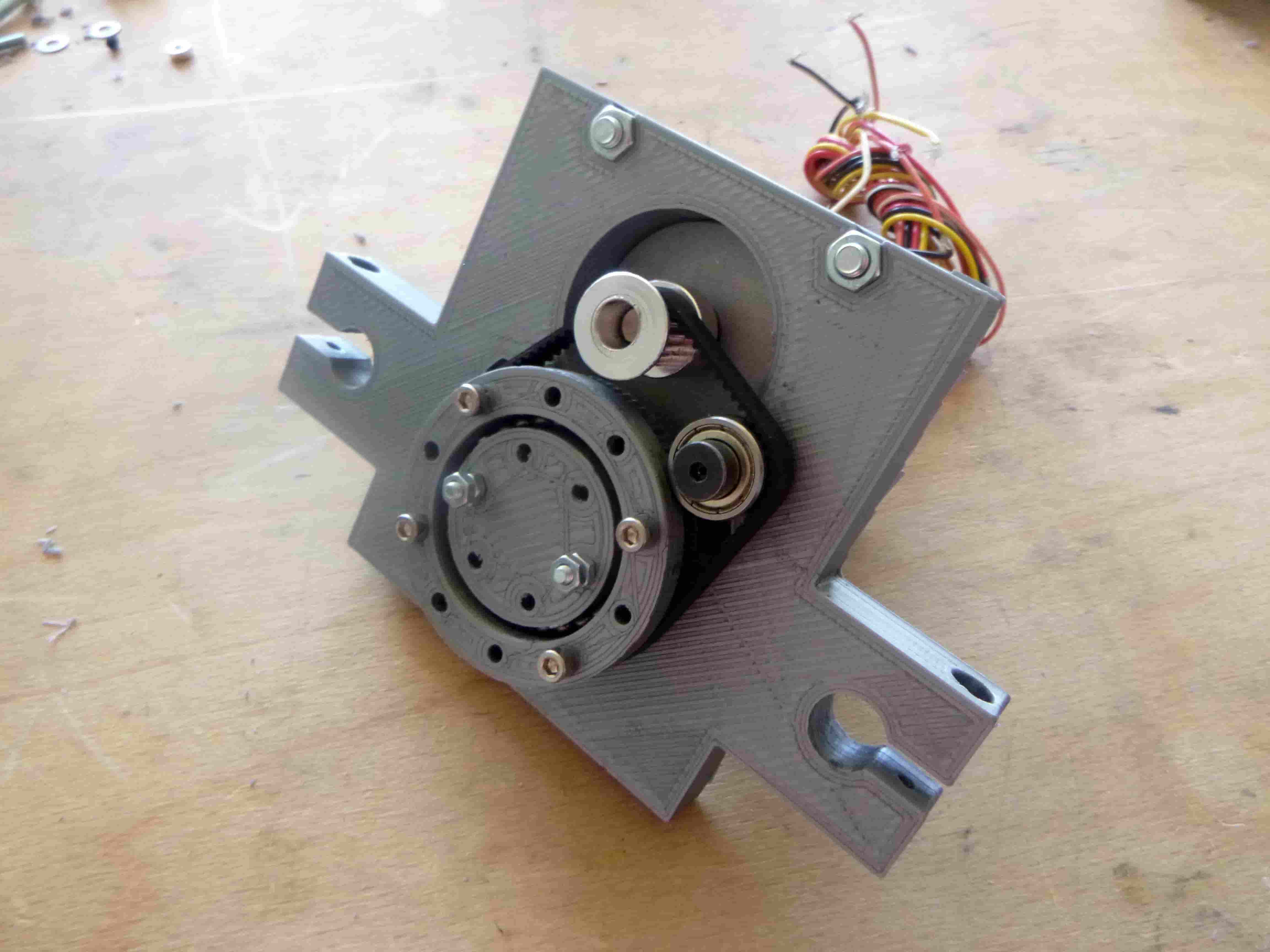
With the belt and motor assembly:
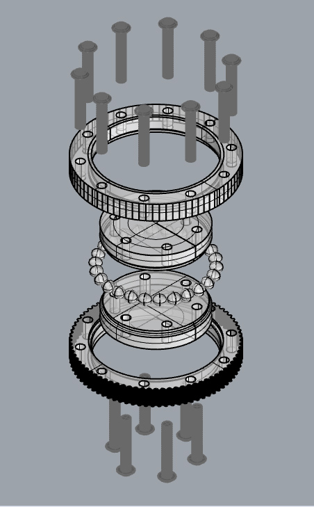
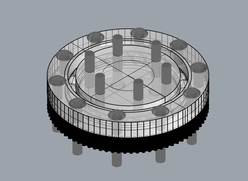
Here is the bearing itself exploded in 3D:
Unexploded:
Here is my attempt to mill part of the bearing assembly which wasn’t successful:
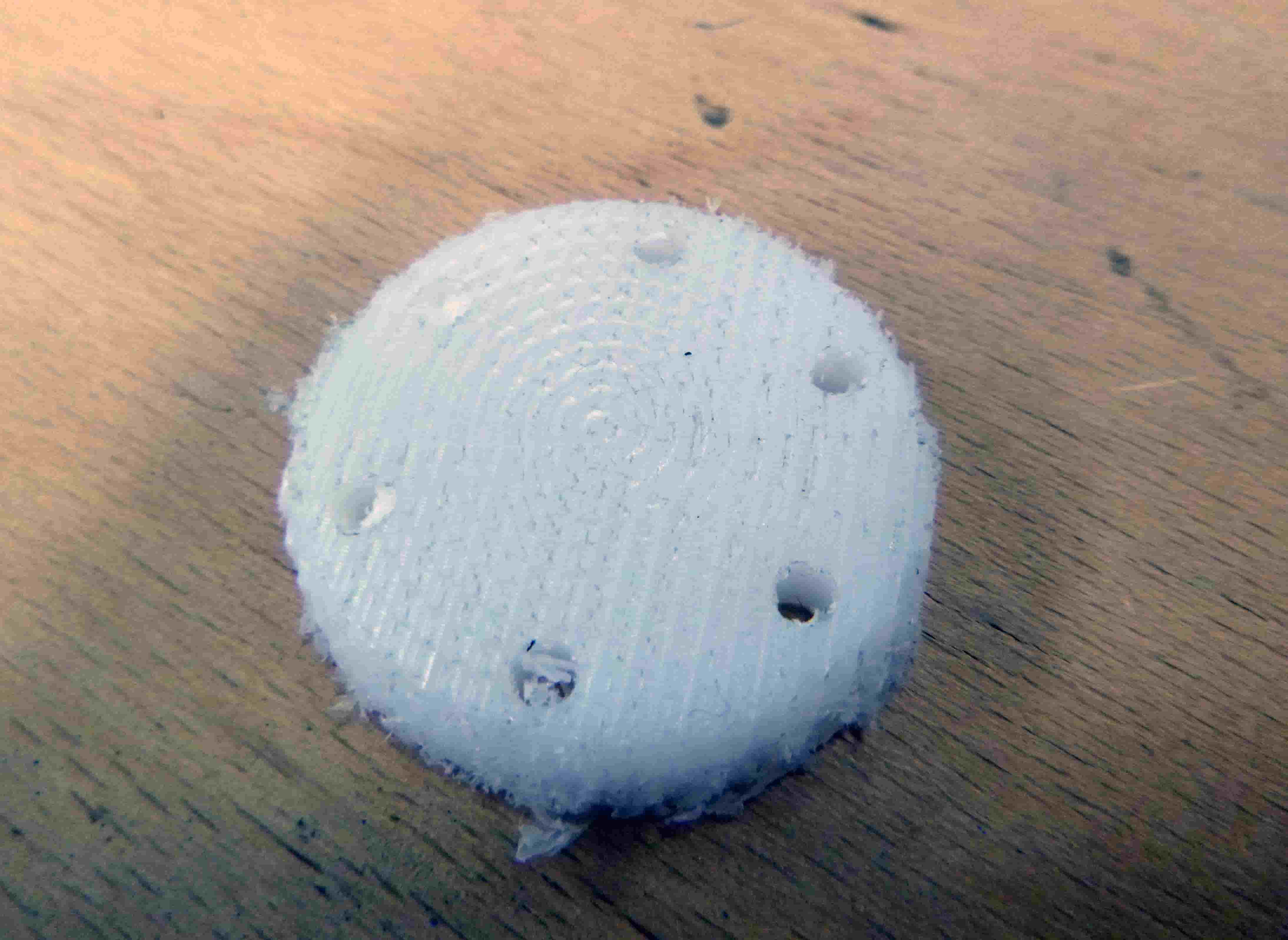
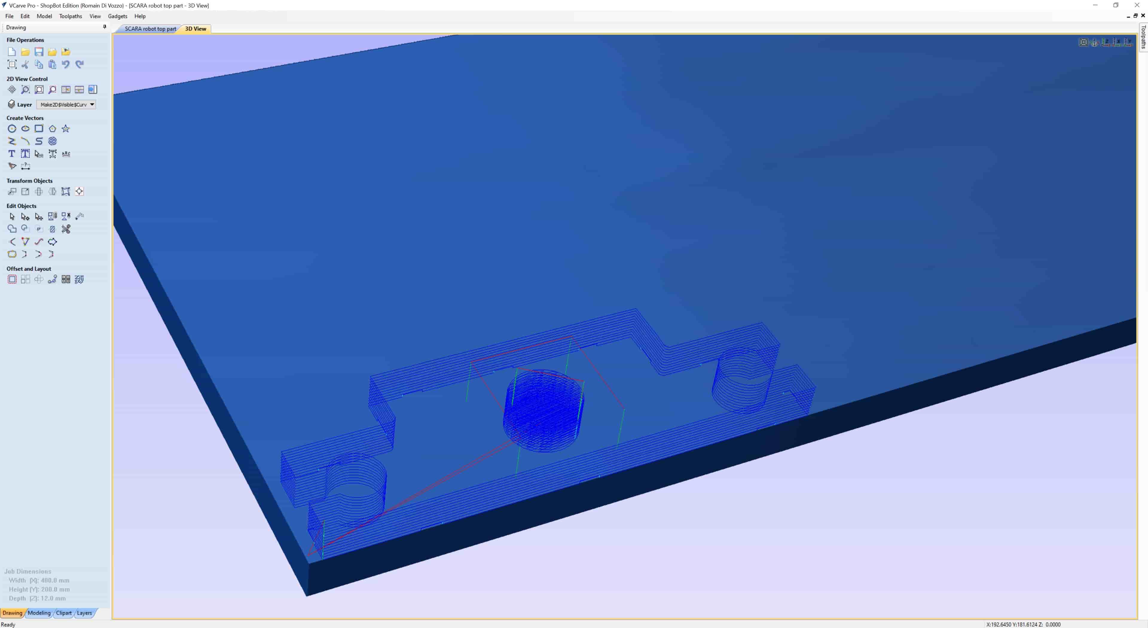
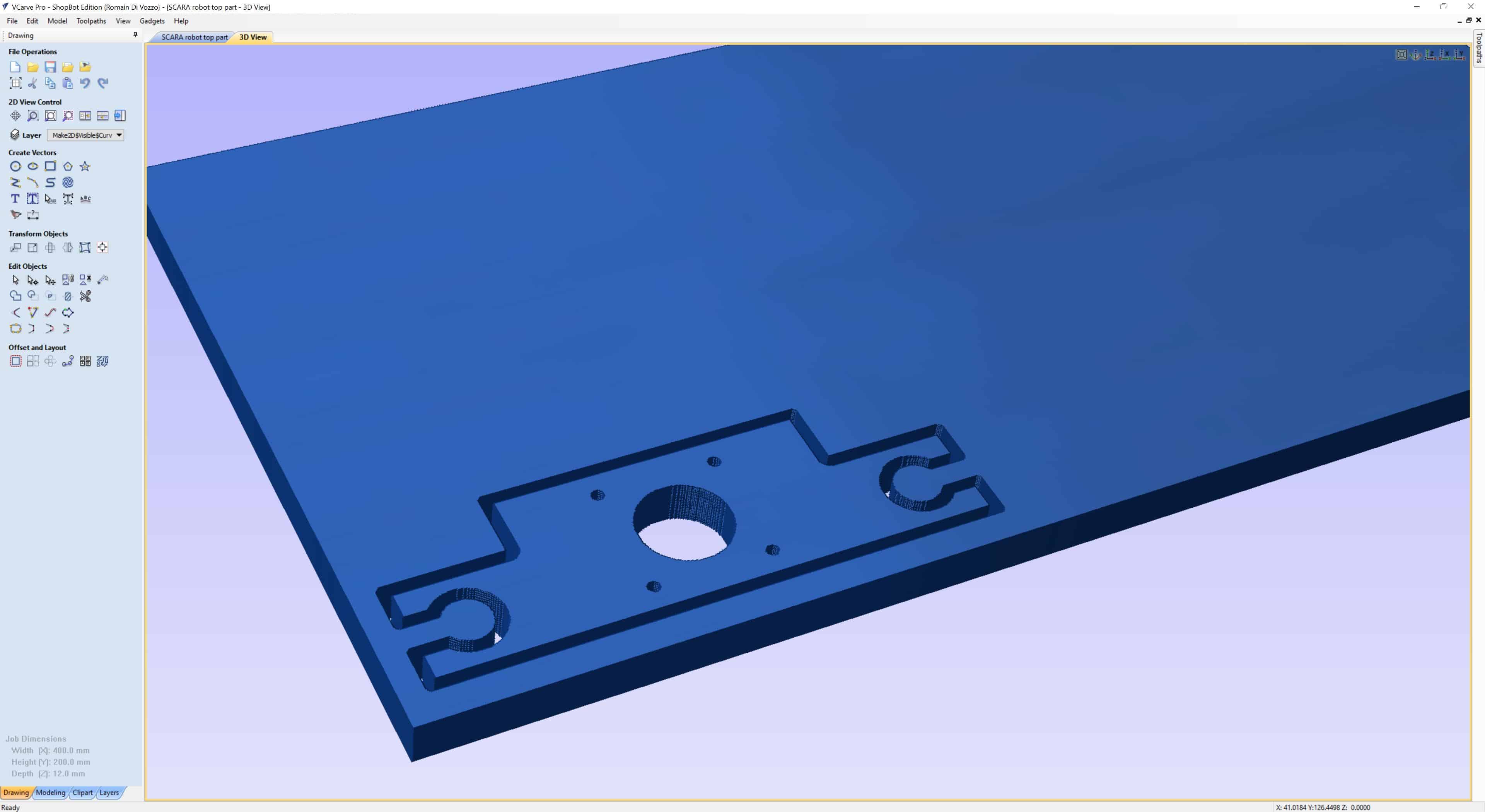
Here was the screenshot that I shows the setup in V-Carve:
And the 3d preview:
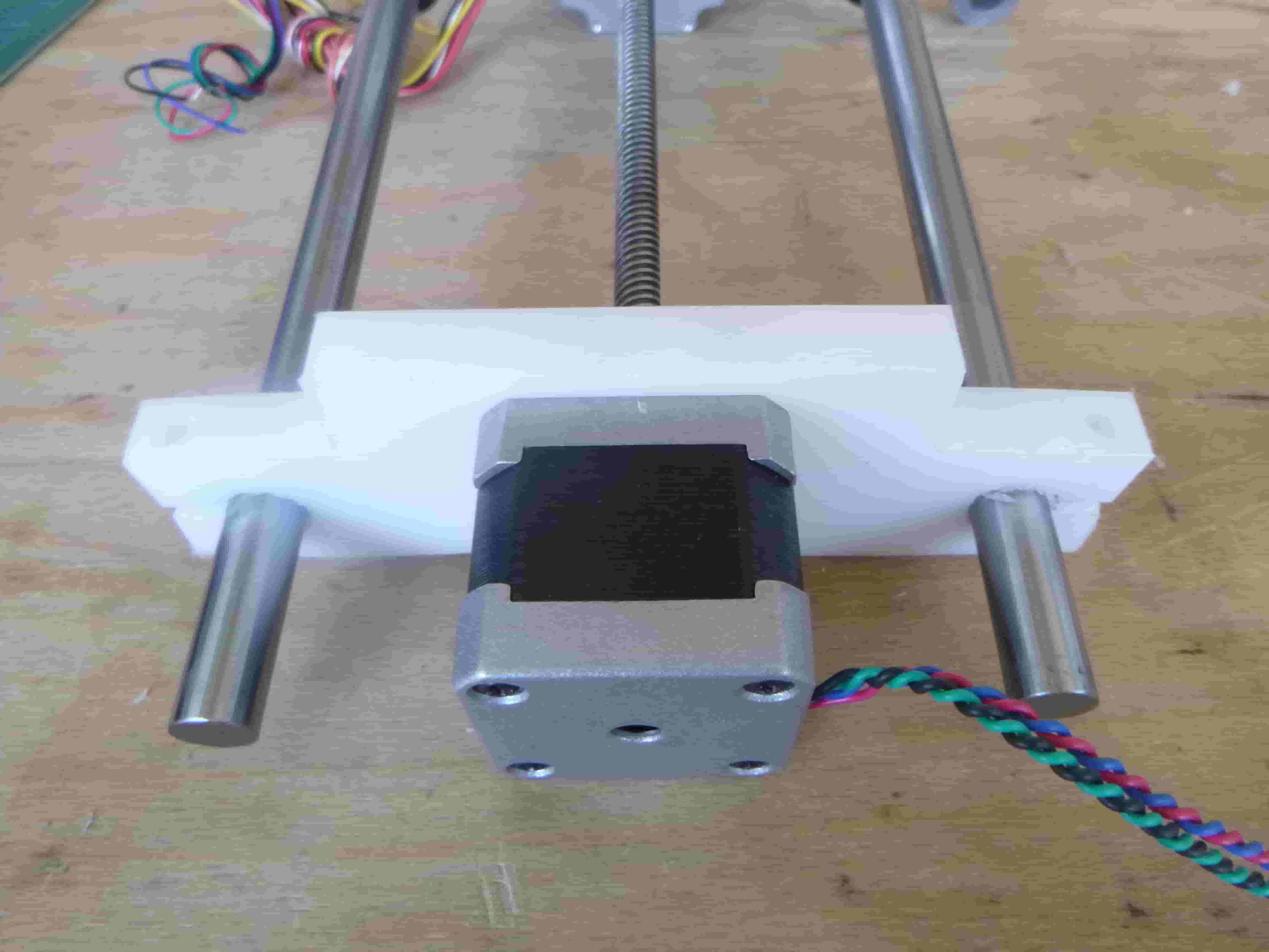
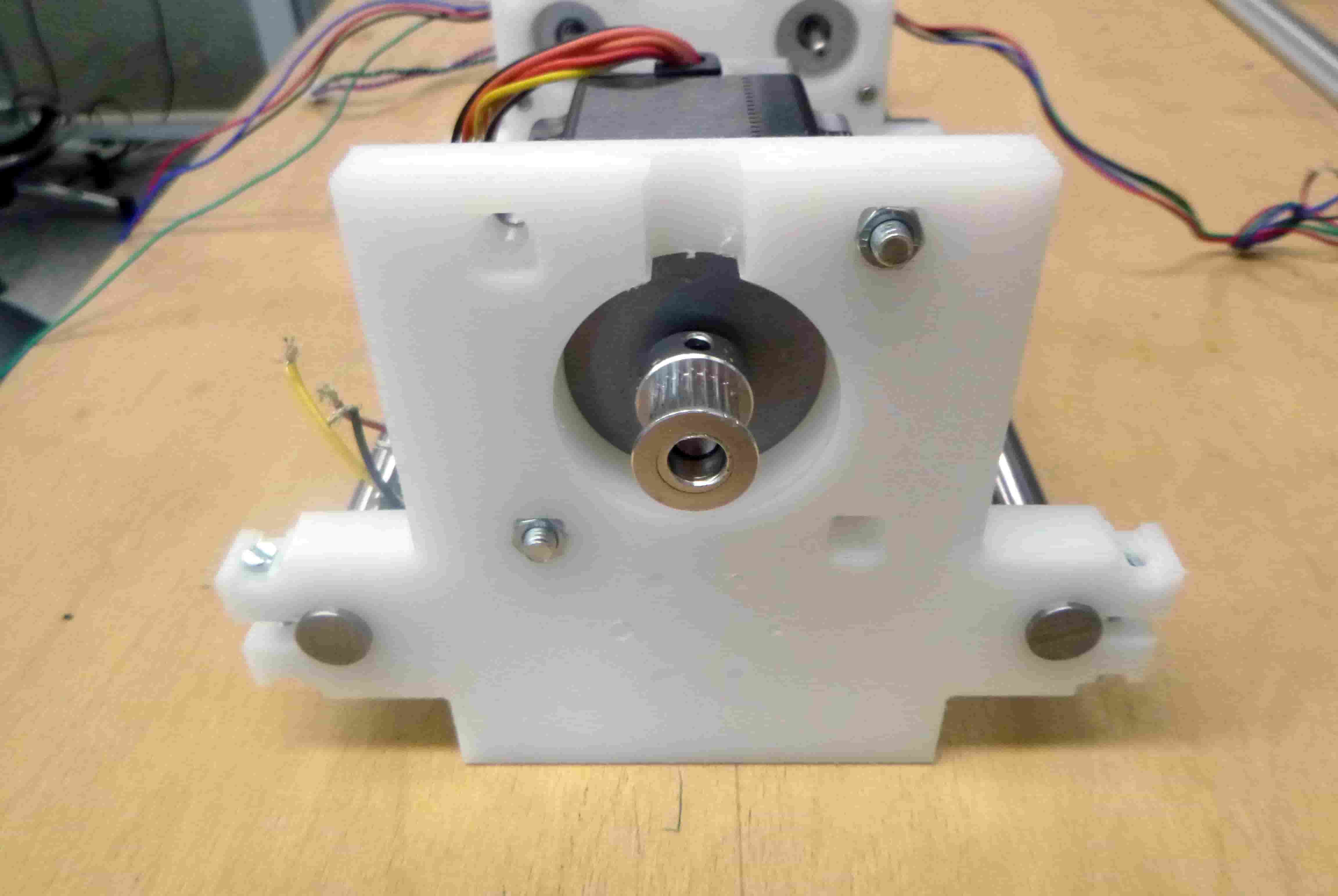
And here is a close-up of the 5 bar arm mechanism joint with two bearings and hardware:

Individual Assignment: SCARA robot CNC version
Here is a video of me milling one of the parts (the top piece):
Here I have used hot glue to attach a piece of HDPE to the MDF sacrificial layer on our Shopbot.
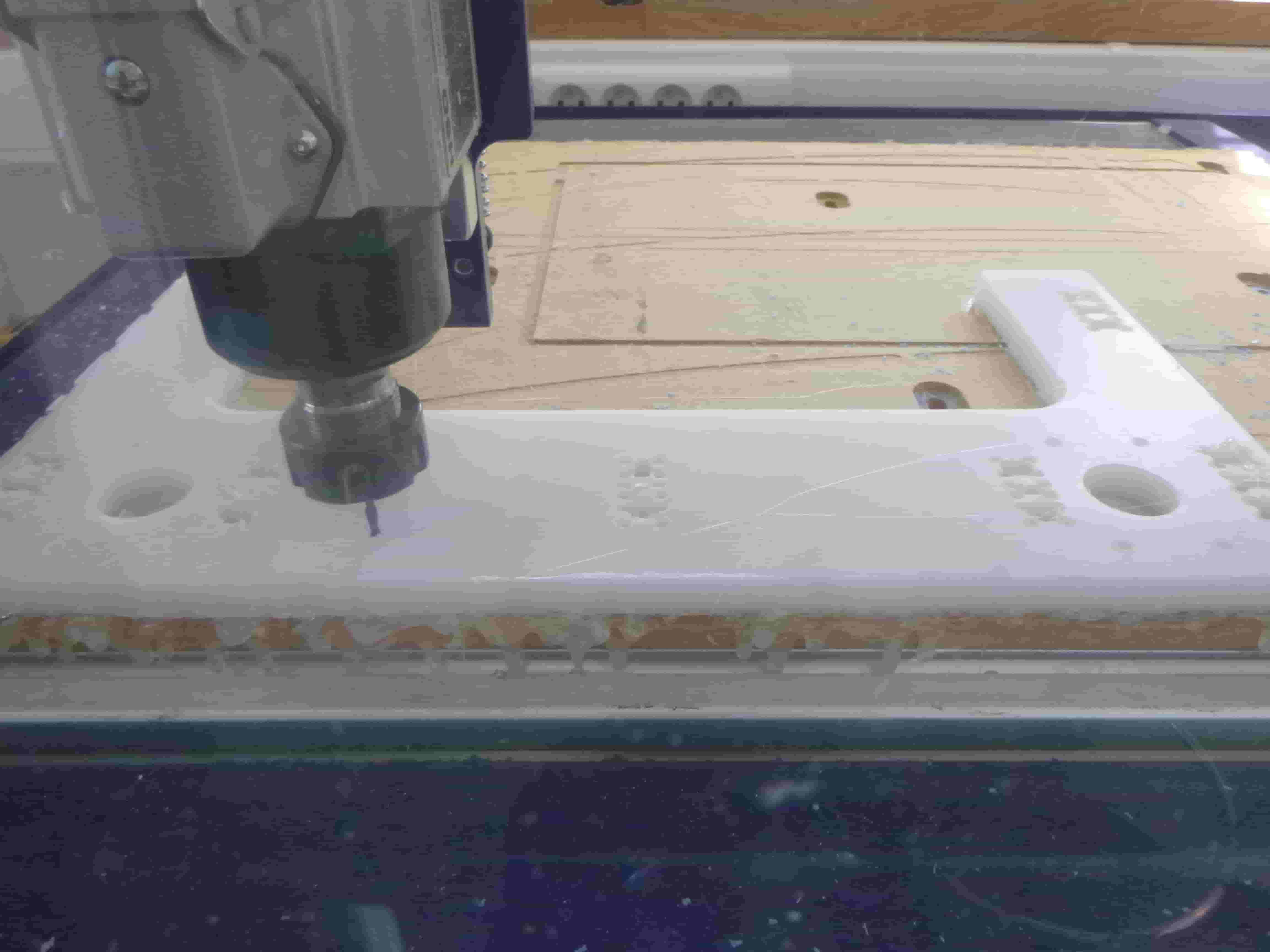
I started with a scrap piece just to test everything was working well. The cut is composed of a pocket in the center and a profile plus a series of drills.
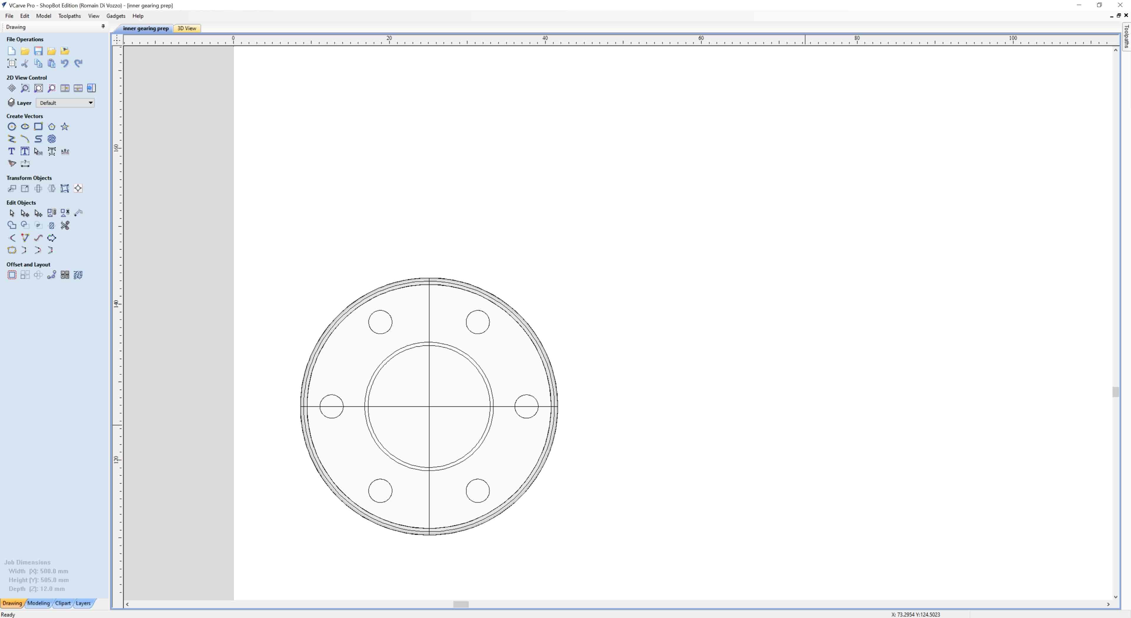
Here is the job in V Carve being setup:
In top view…
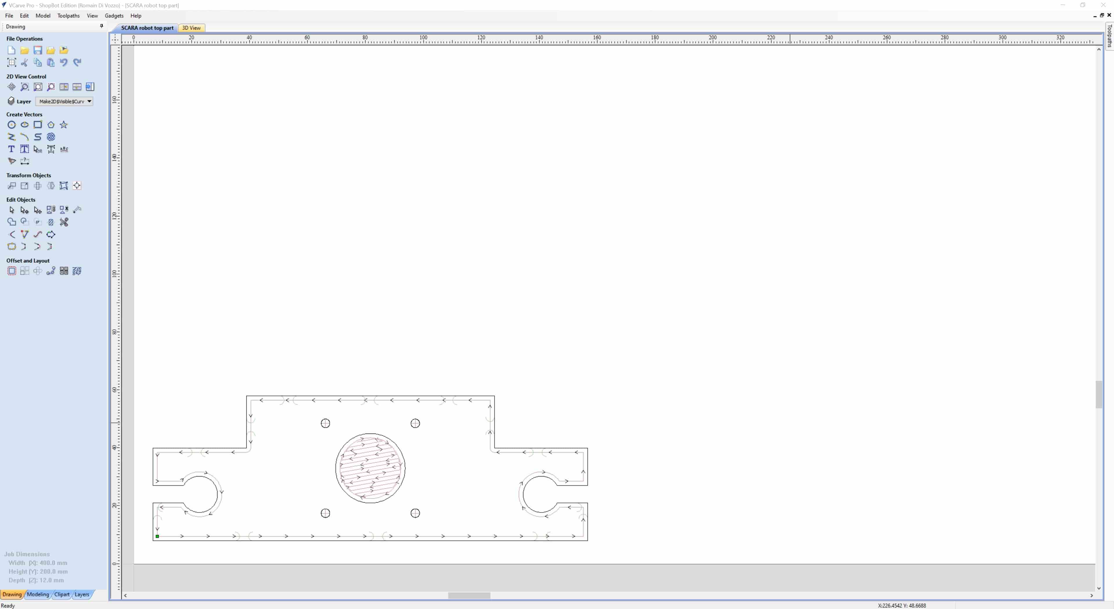
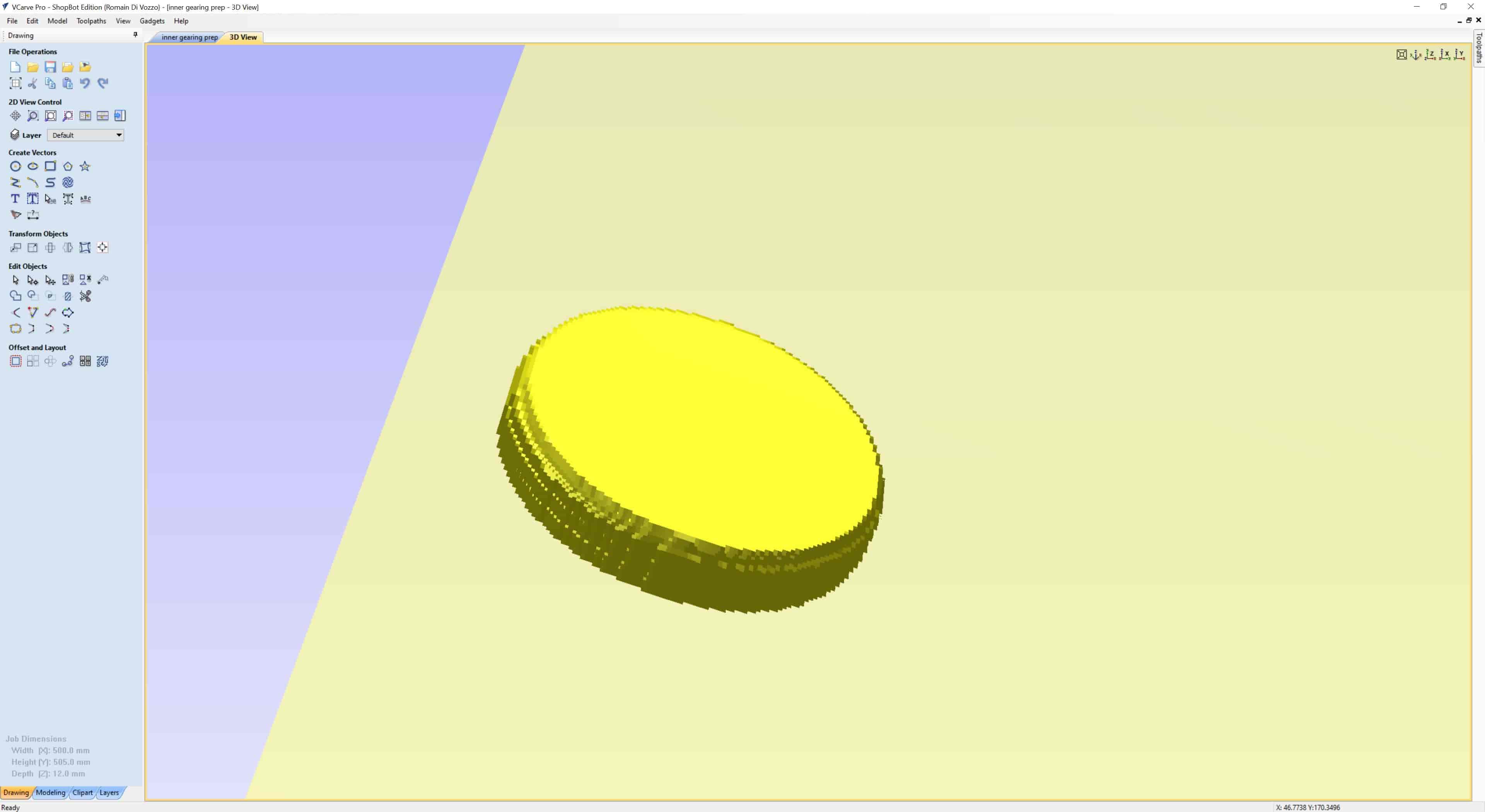
And previewed:
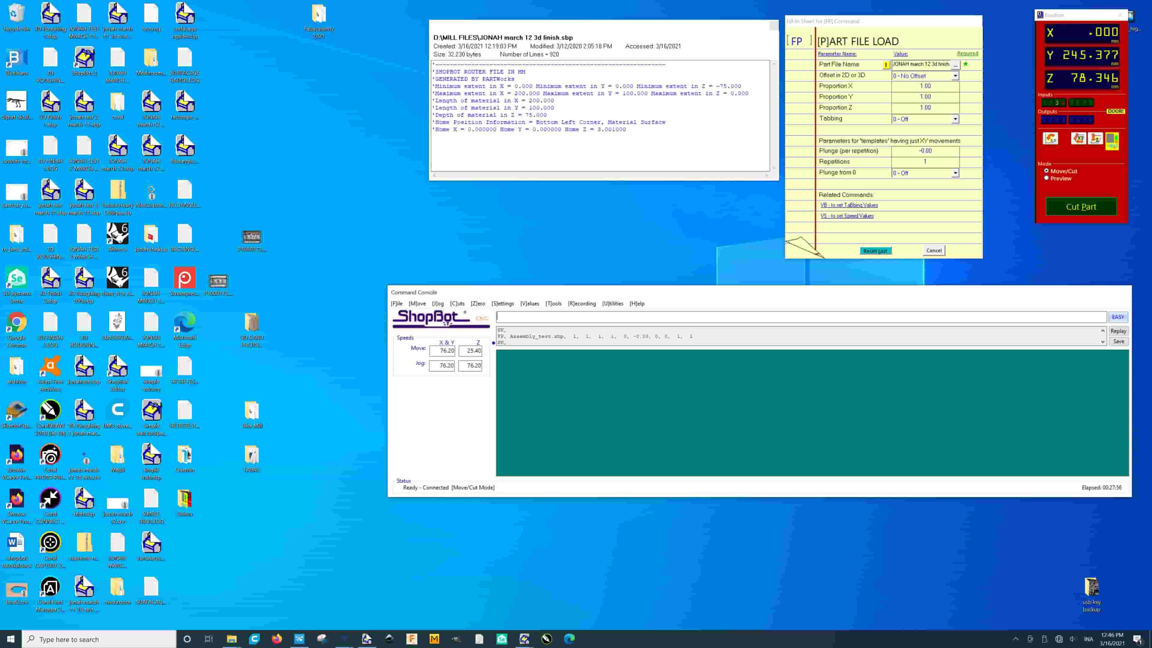
Here is me sending the file to the machine with Shopbot:
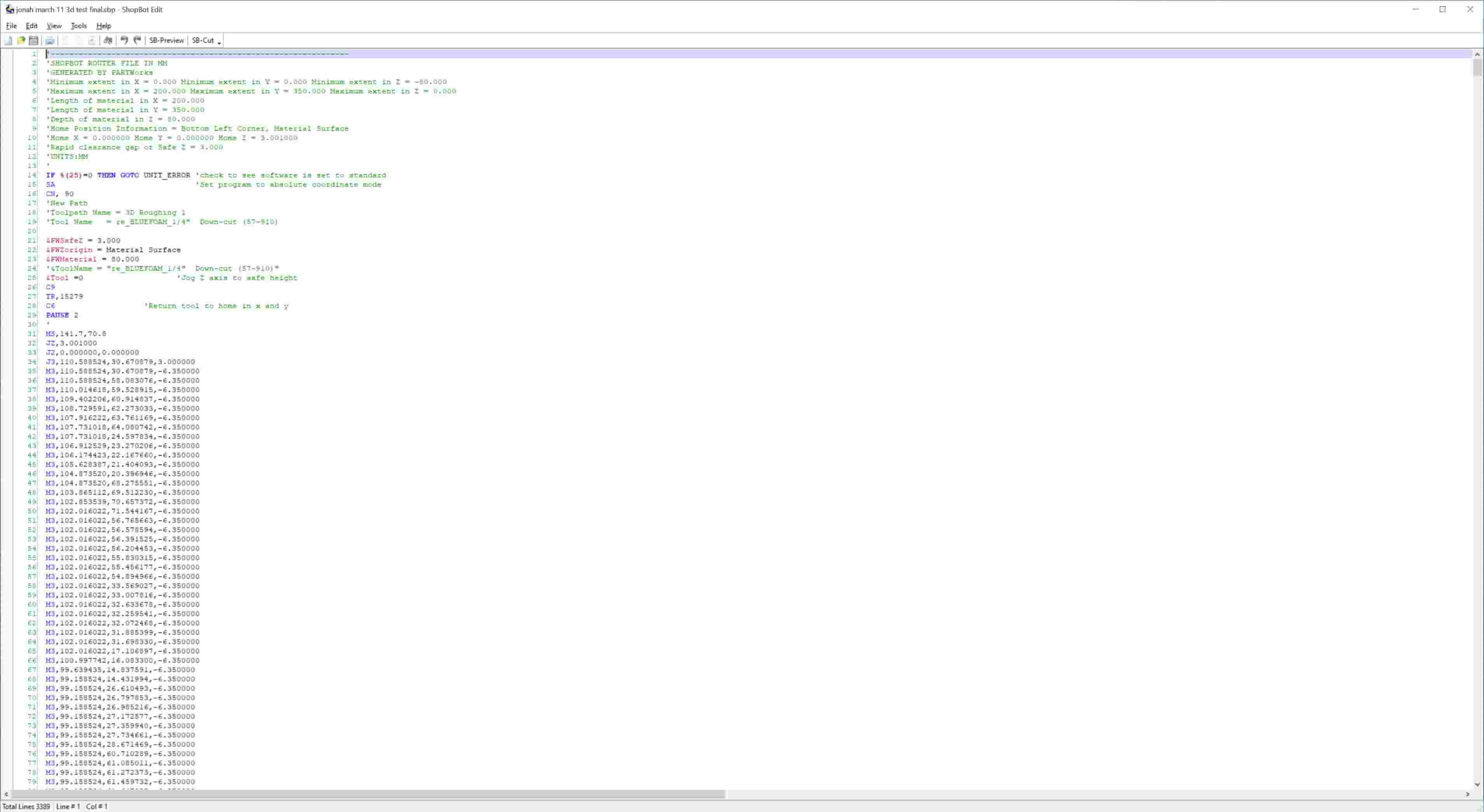
And here is the actual G-Code generated by V-Carve:
The HDPE is 12mm thick and mills like a dream.
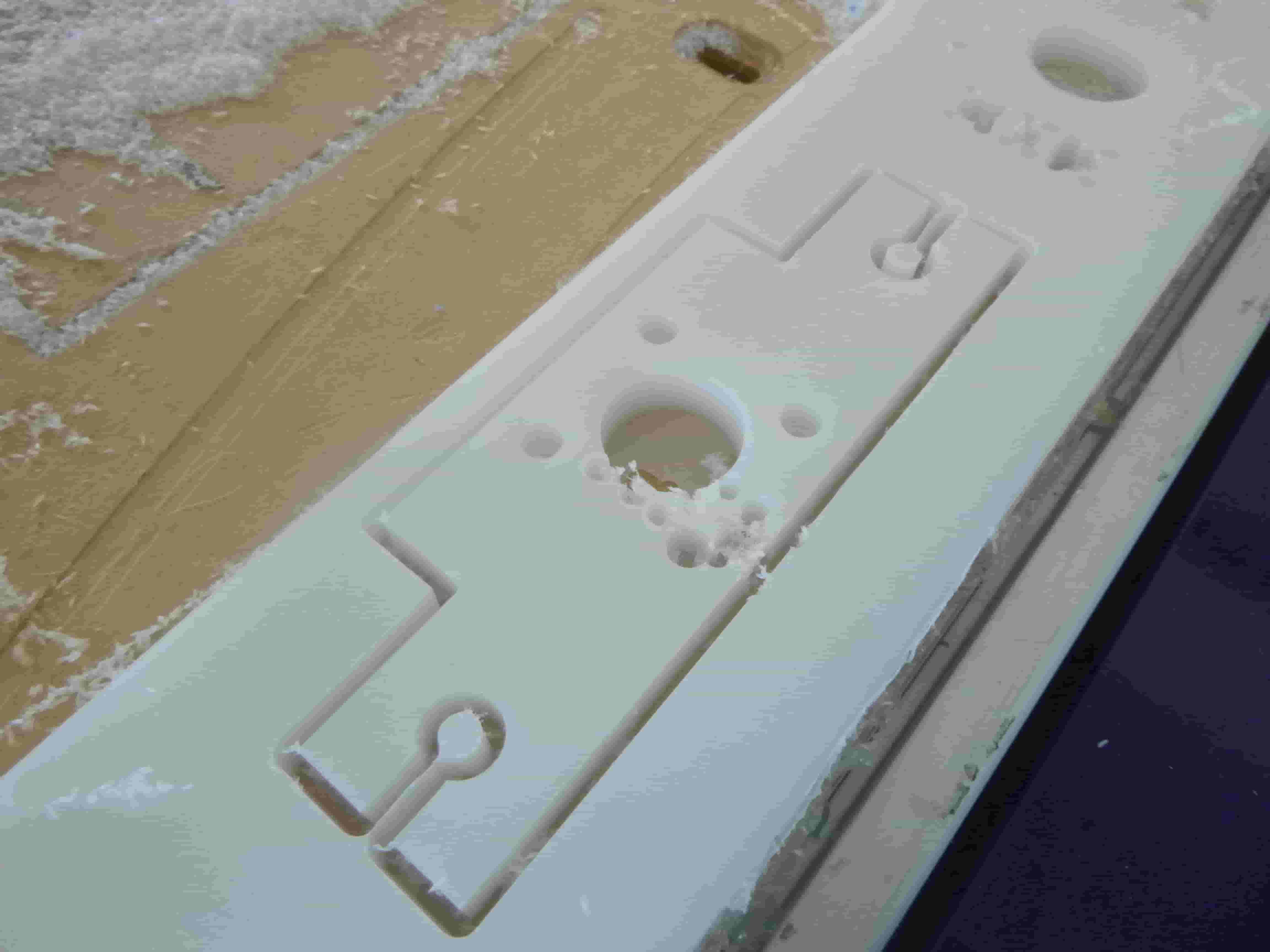
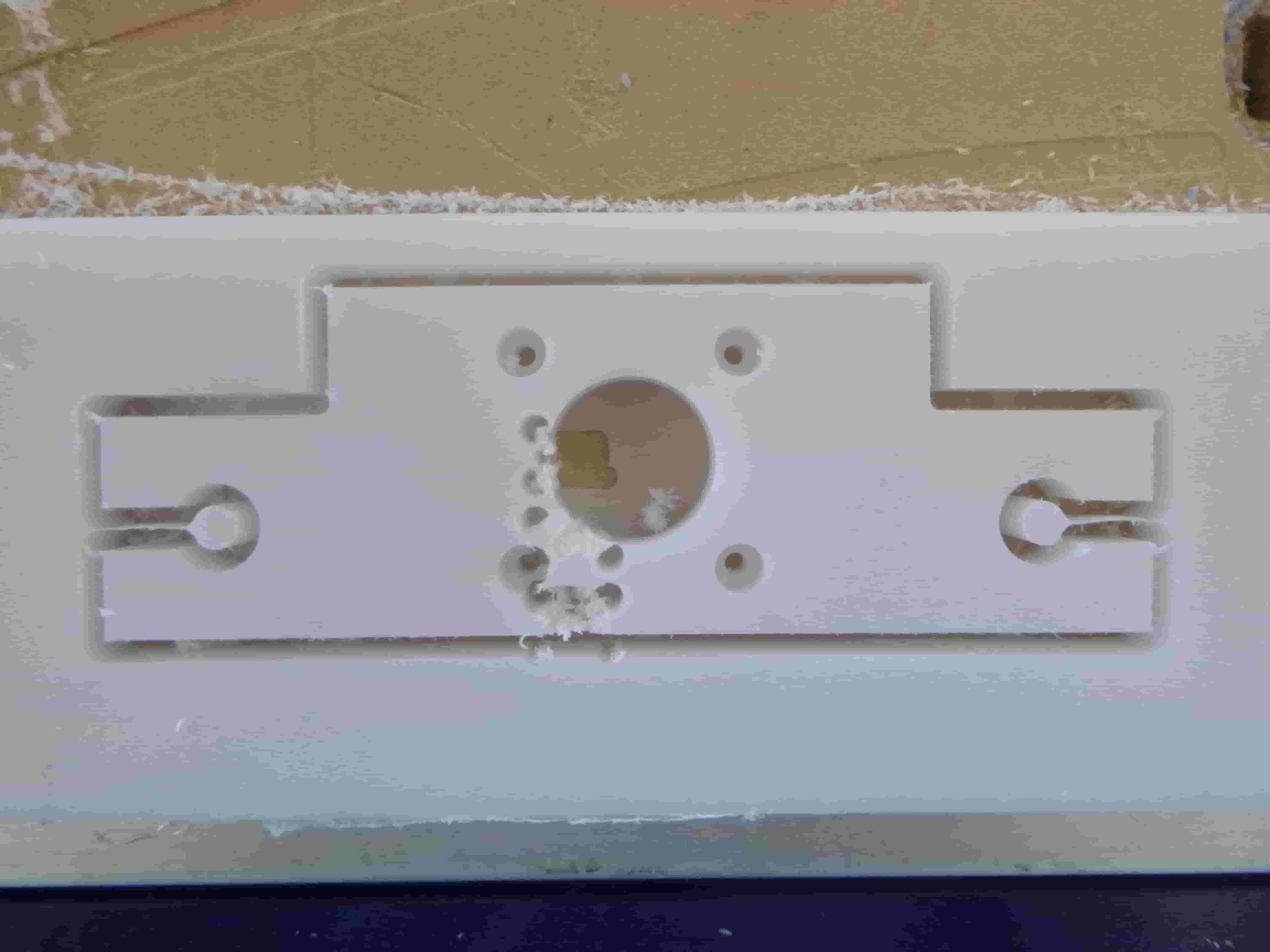
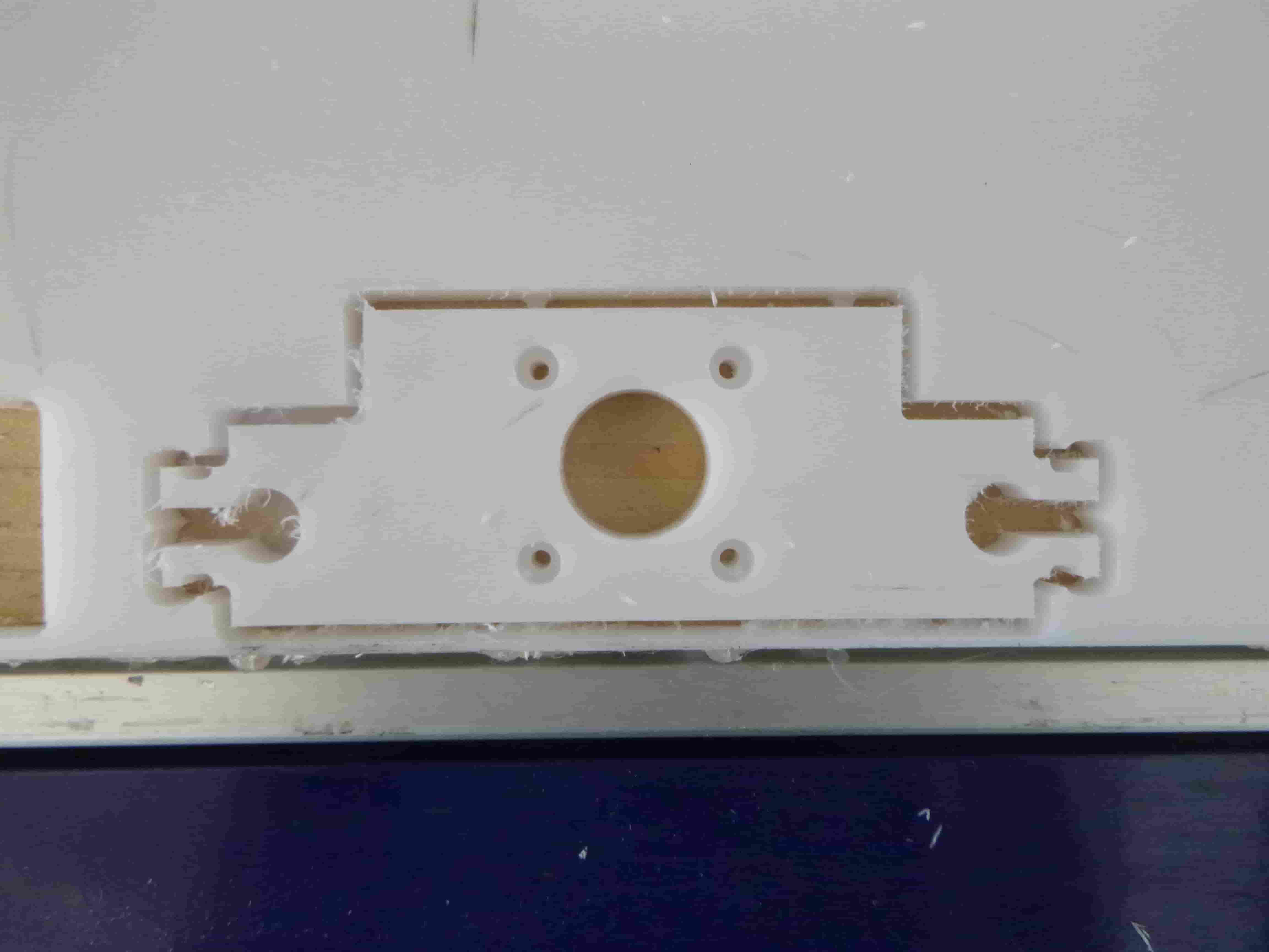
Here is the piece removed. I had 1mm tabs which survived the milling process and were easy to remove.
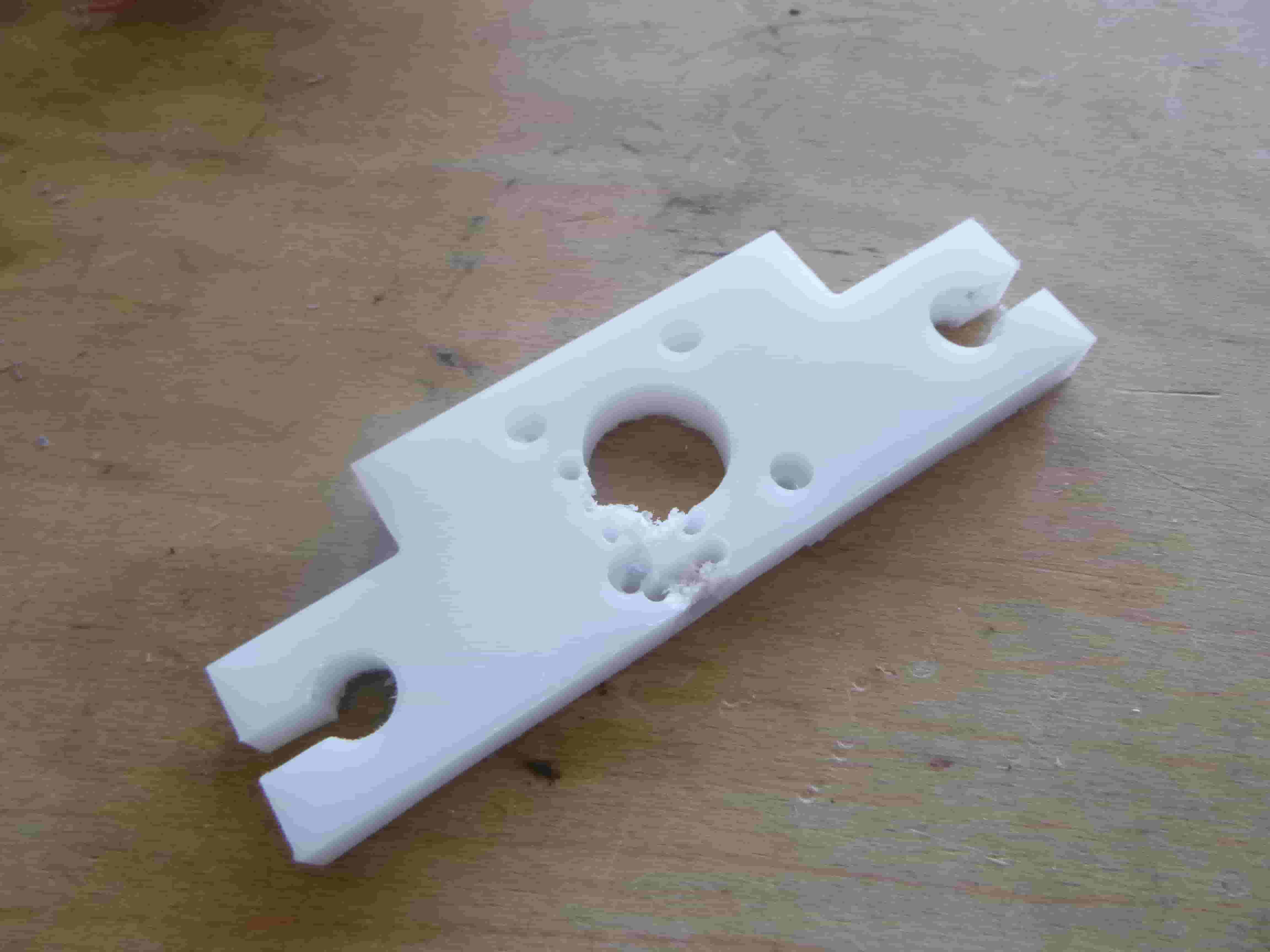
I have right angles for the exterior edges.
I manually drilled a hole on both sides for the bolt that is to come and hold on to the rails.
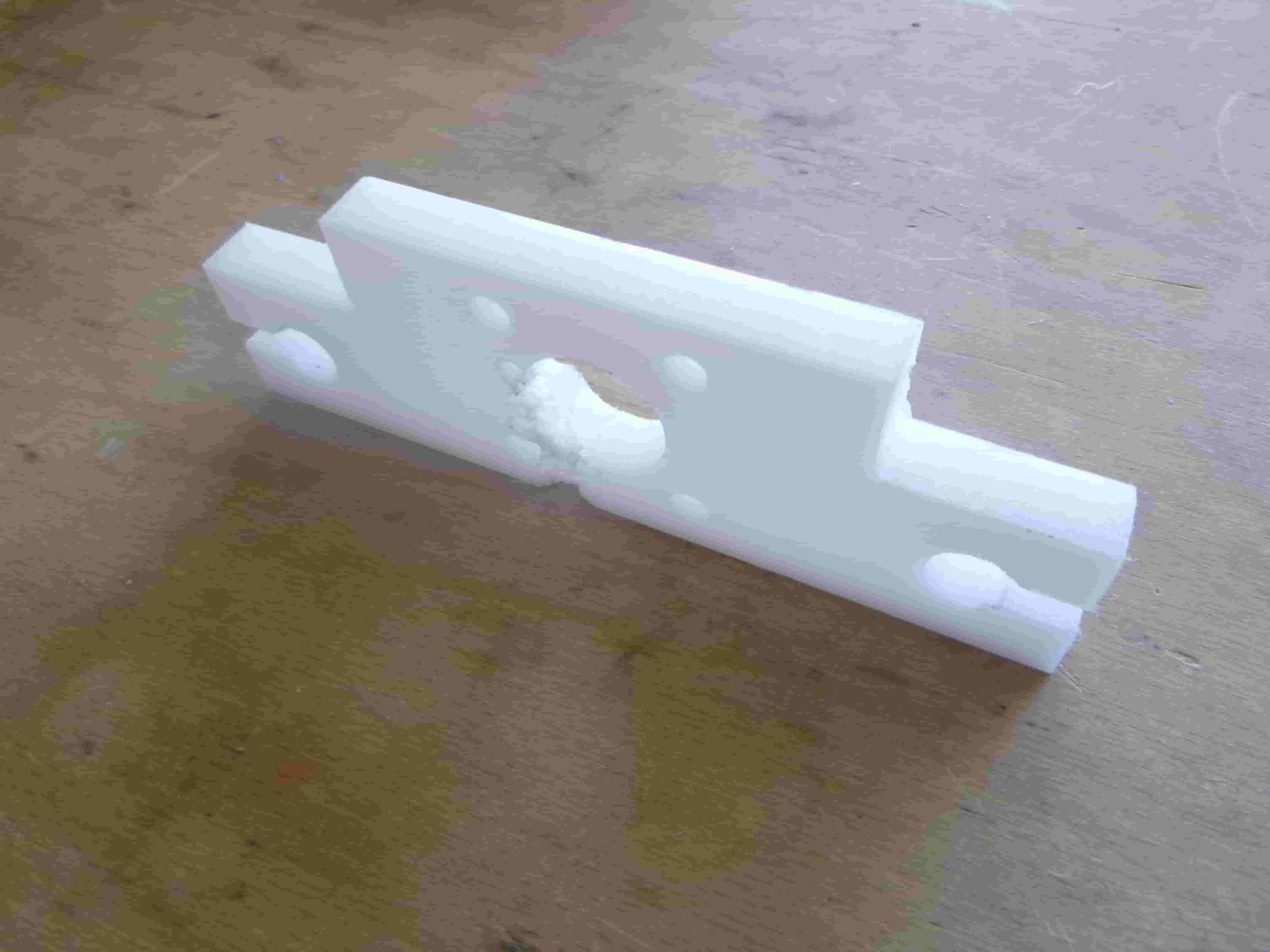
Here is the same piece laying flat on a table surface.
From behind and showing the bolt holes I drilled (despite the heavy image compression this is hopefully visible):
Here is the recut of the same piece but from a non scrap piece of HDPE:
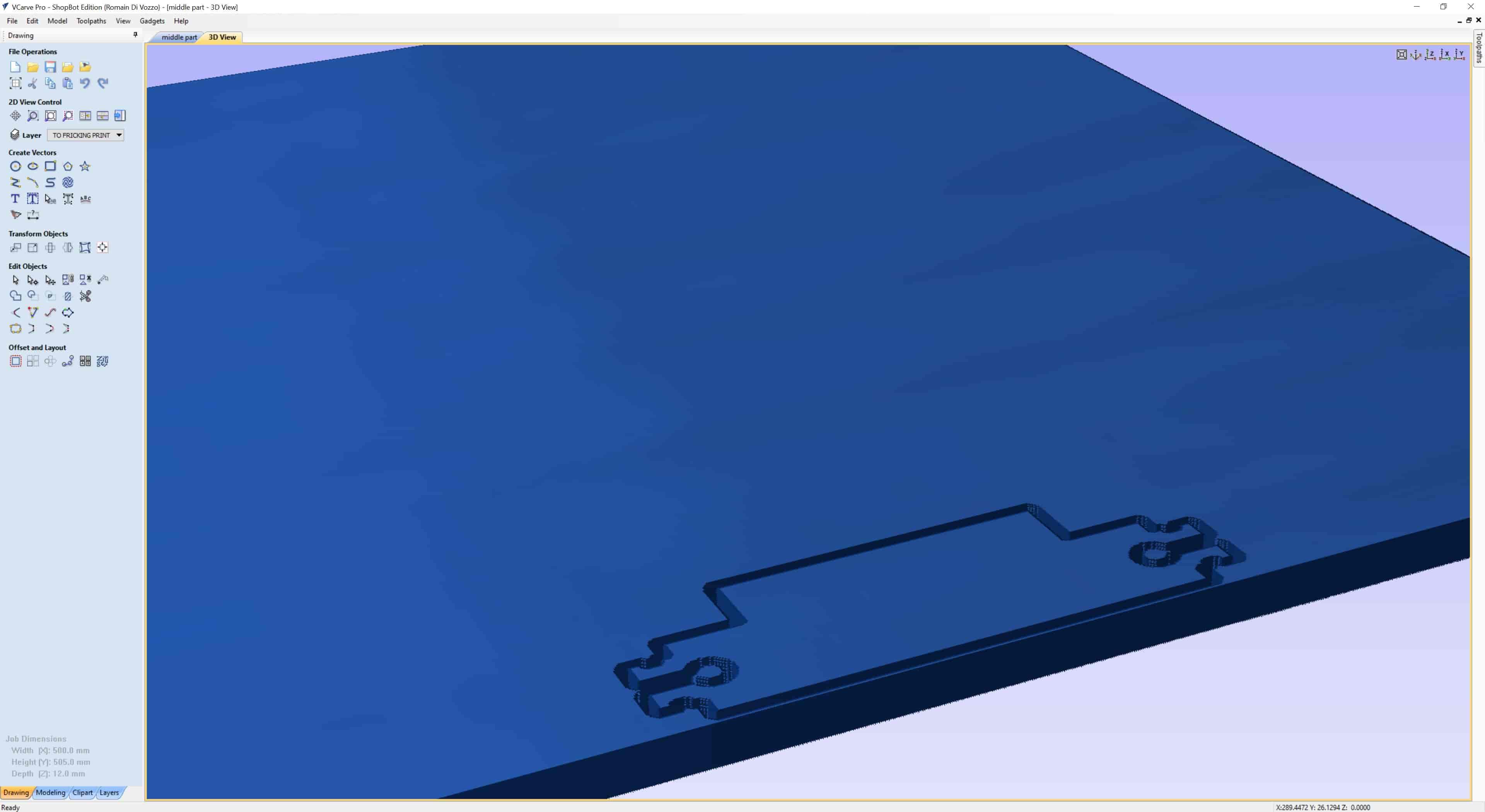
Here is the V-Carve file prep for this piece:

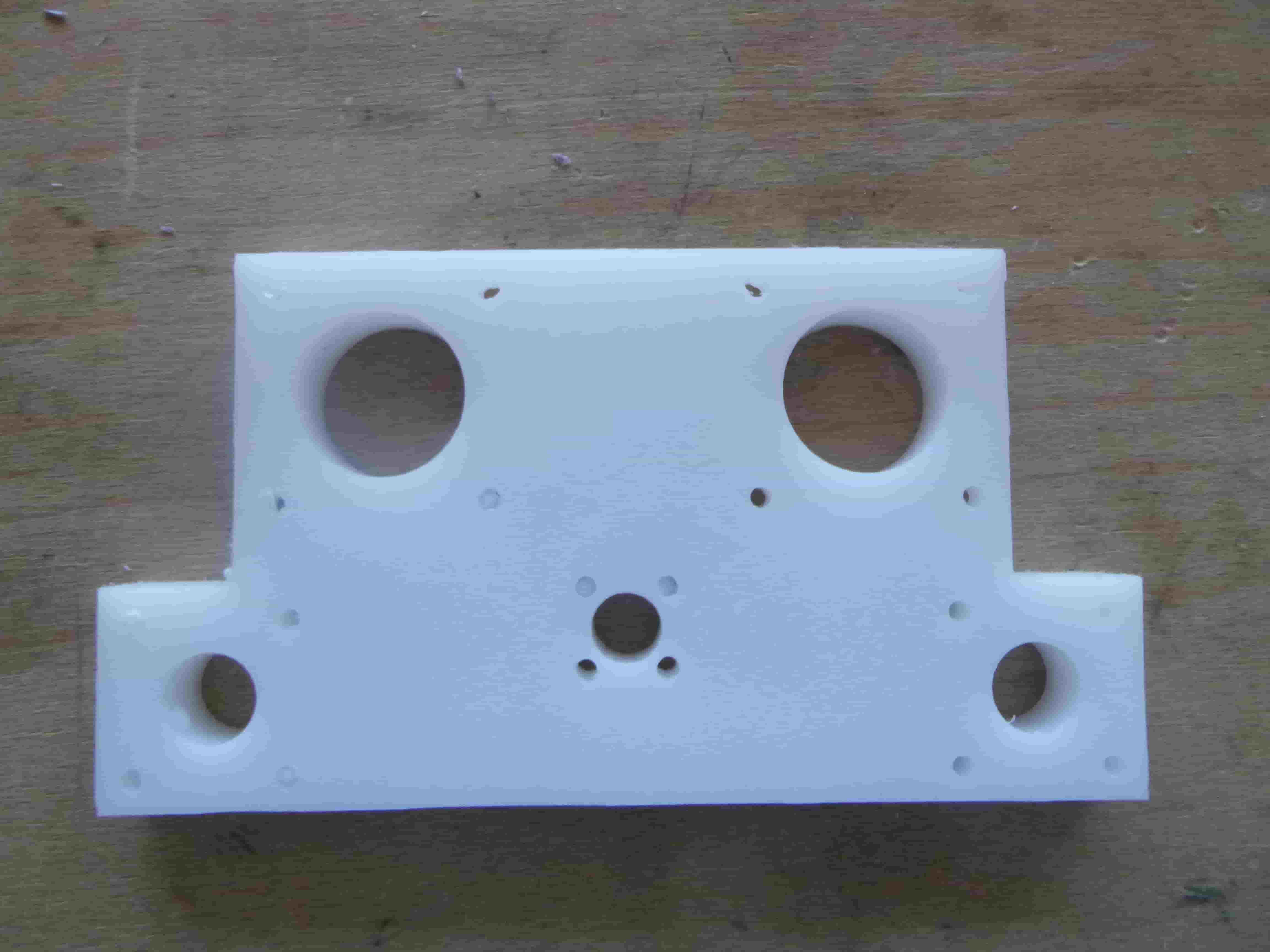
Here is the completed middle piece coming out of the mill. I have made shallow drills for the heads of the bolts and am no longer using scrap pieces:
I cut it as close to the bottom left corner as possible so as to not waste any material.
It turned out just as I had expected!
I had to remove a thin layer of HDPE from the inside of the holes but otherwise everything was cut very nicely.
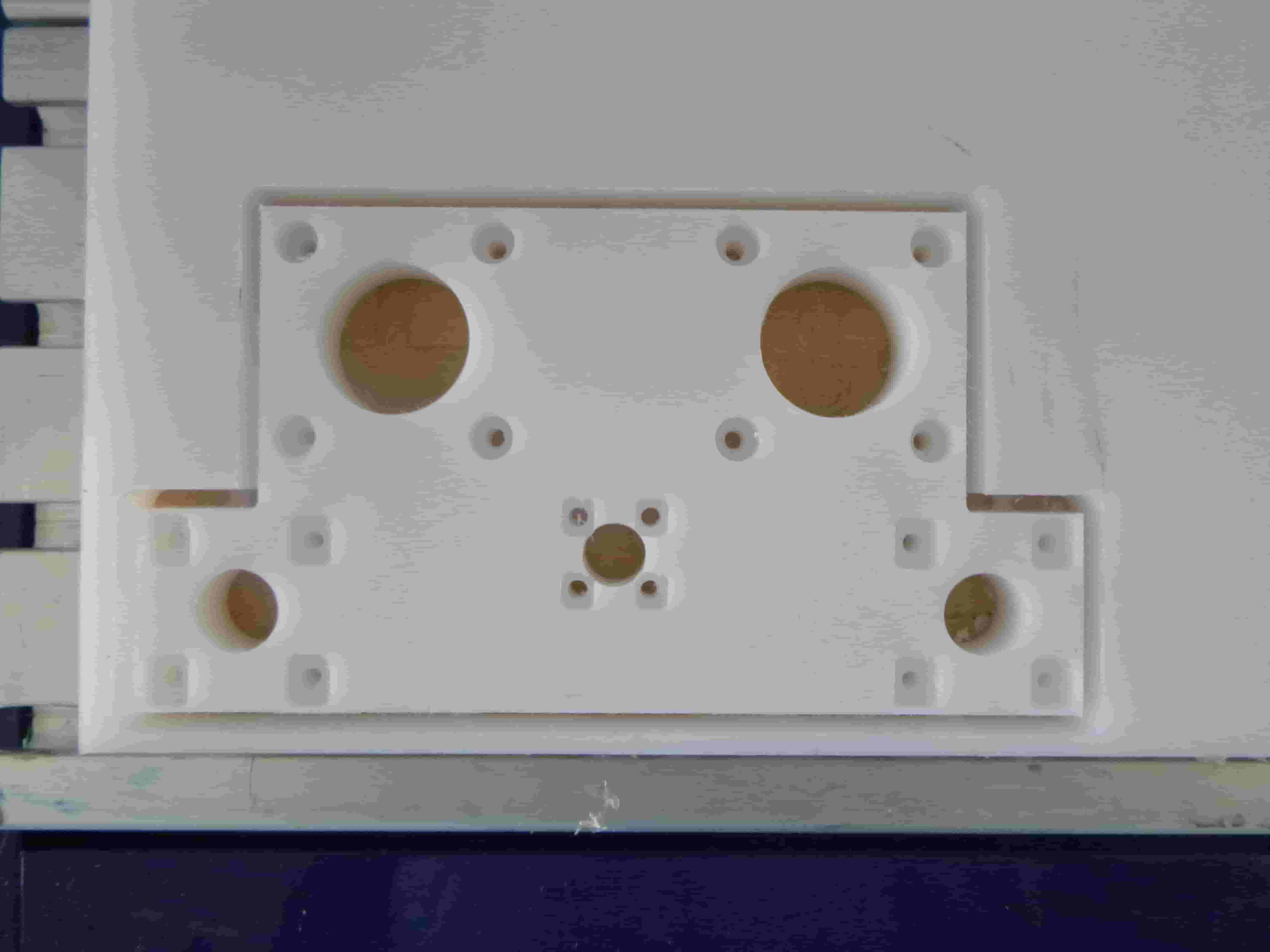
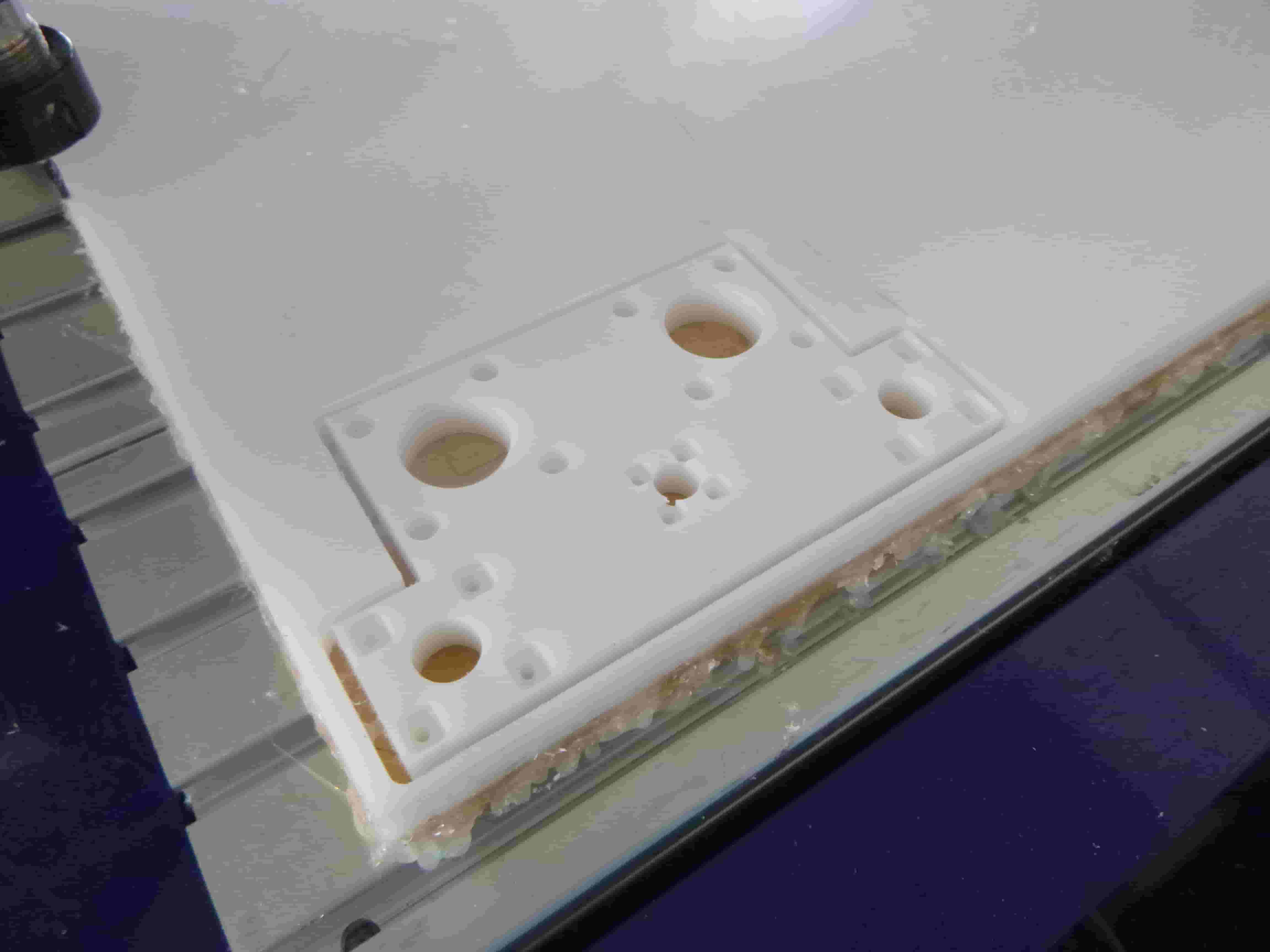
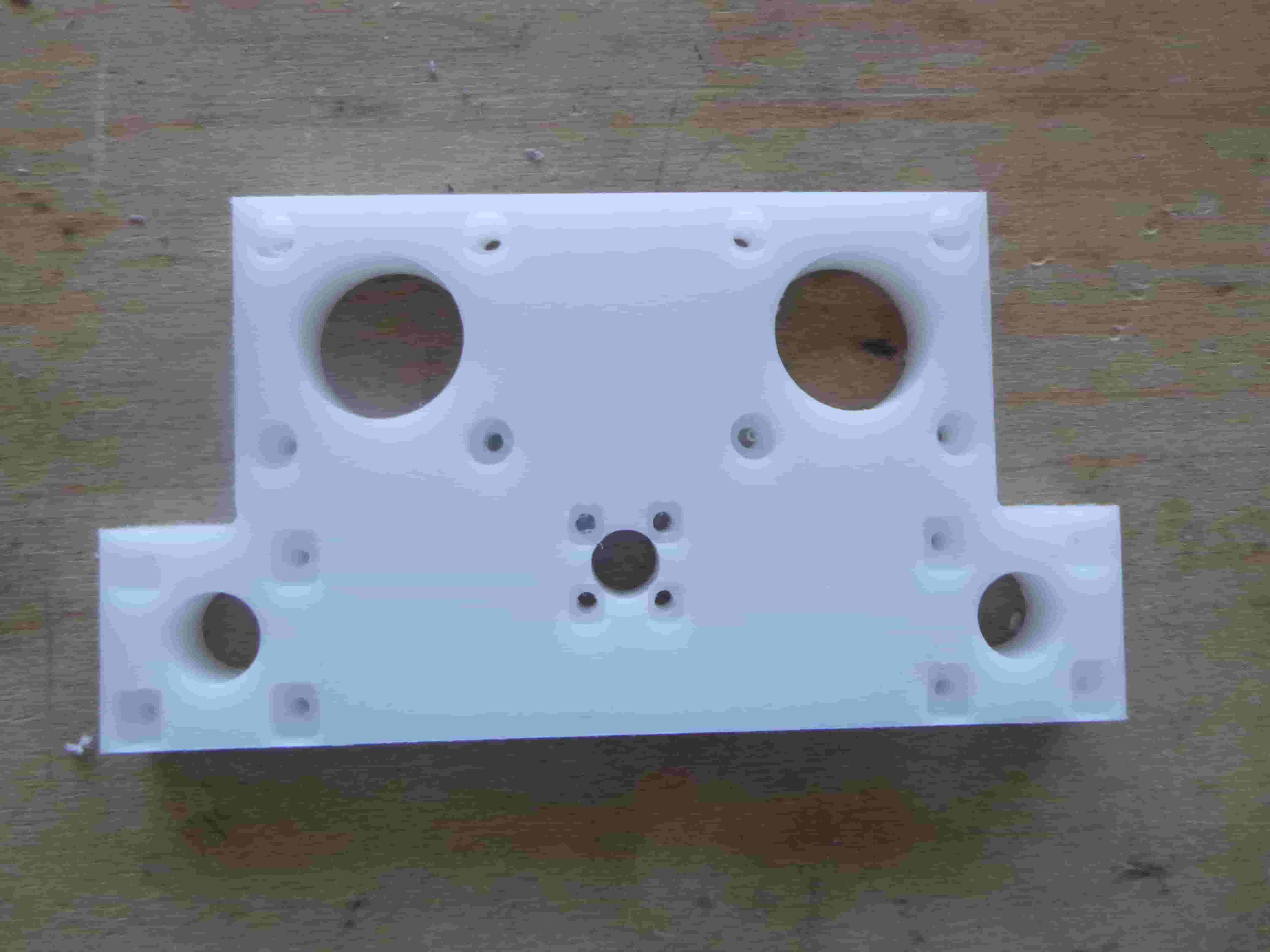
The flip side of the same piece, showing the shallow drills to make space for bolt heads and the square holes which will hold the nuts.
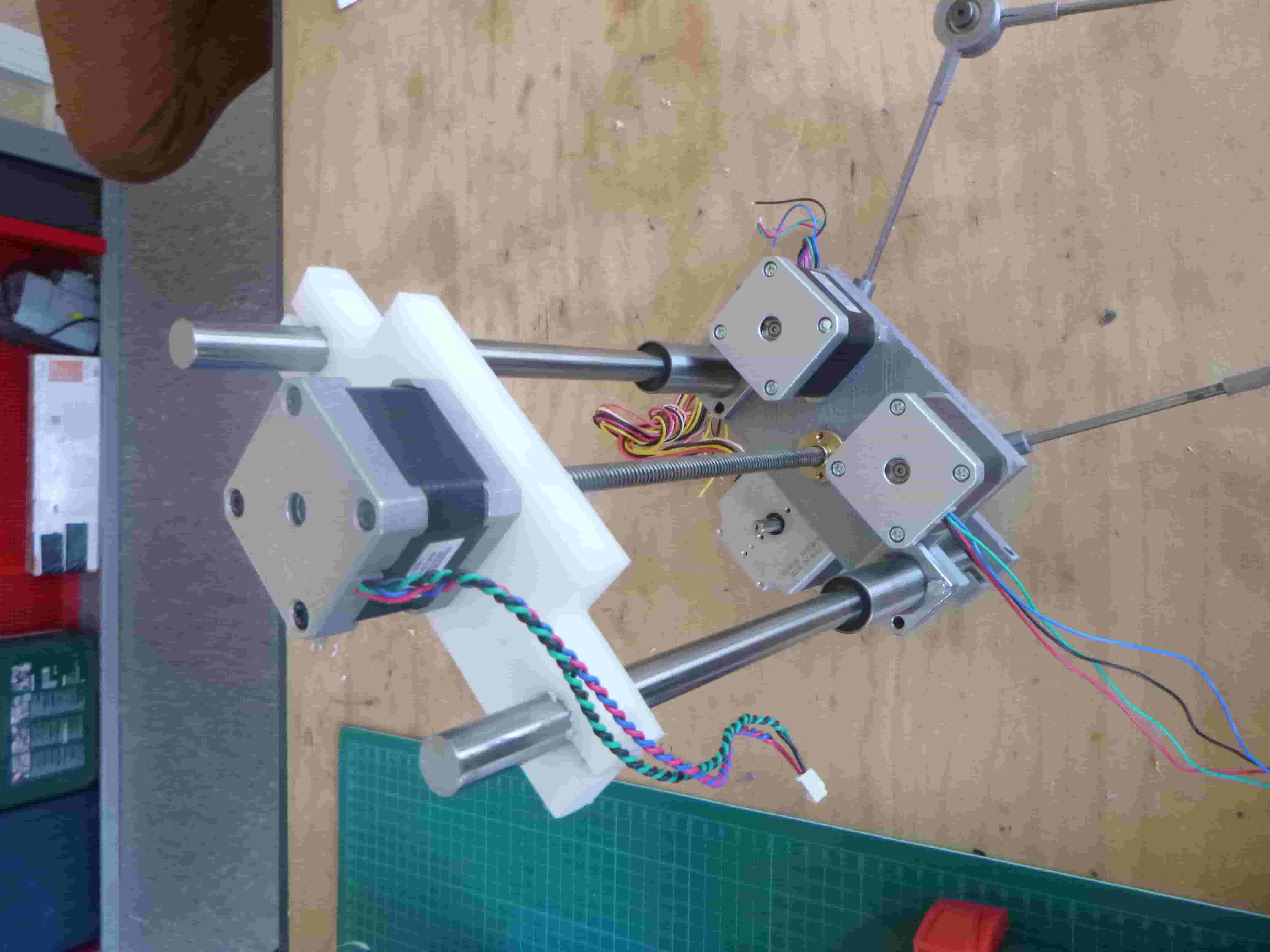
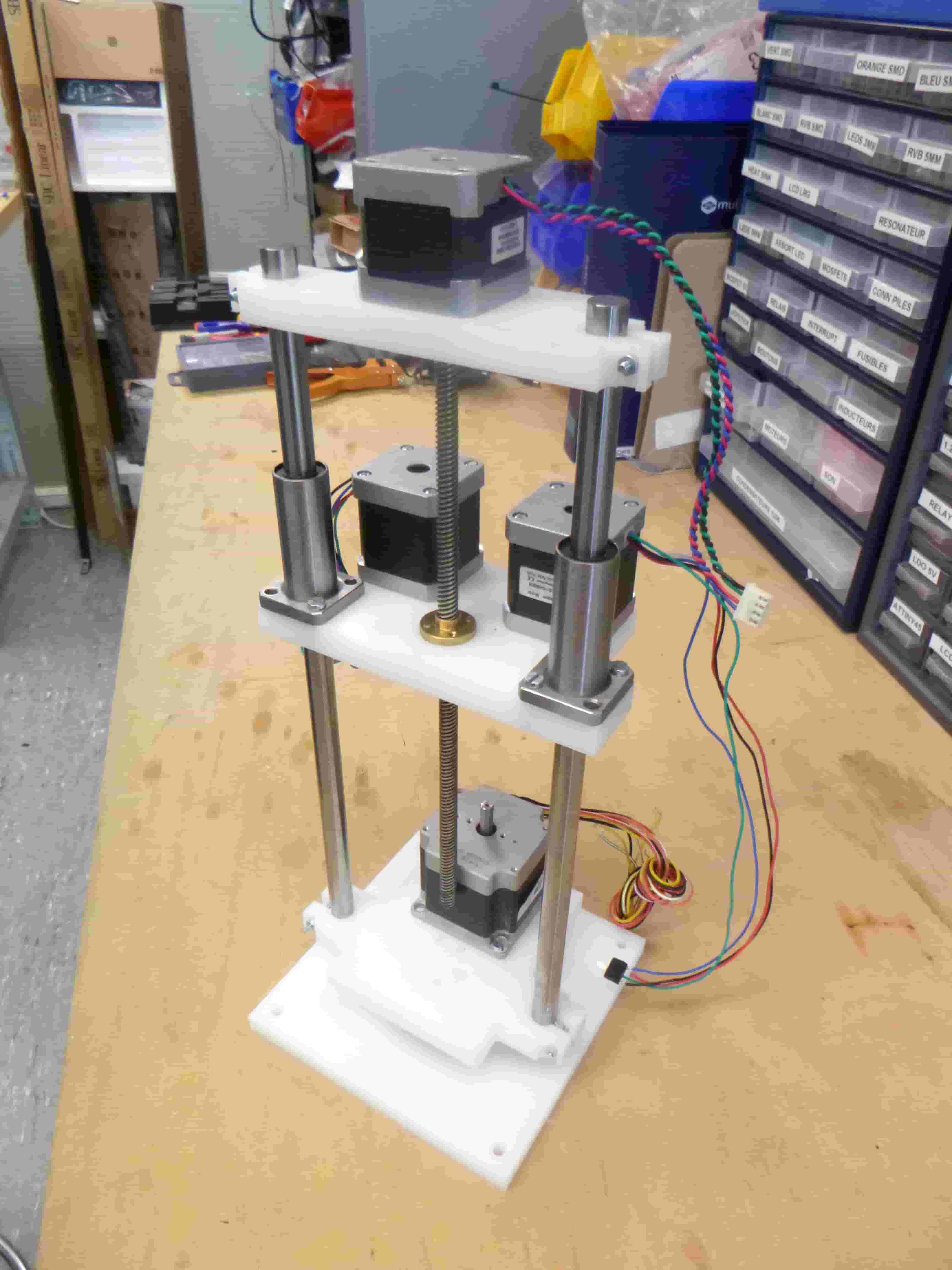
Here is the 3D printed version with its top and middle parts replaced with HDPE:
Laid down to show the organization of the robot arm:
To show the captive nut setup:
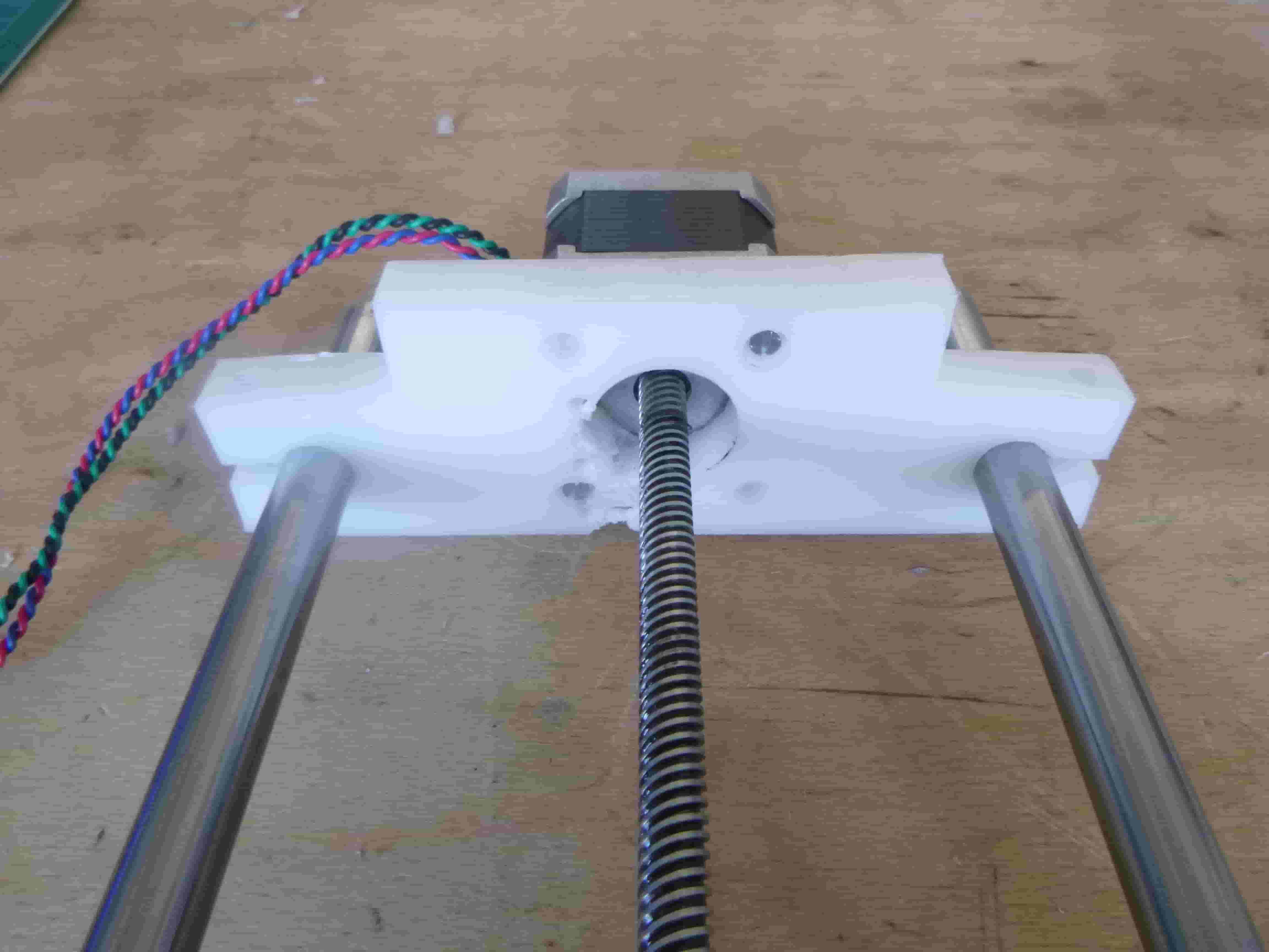
To show everything lining up nicely from above…
…and from the side as well…
…and looking up towards the top:
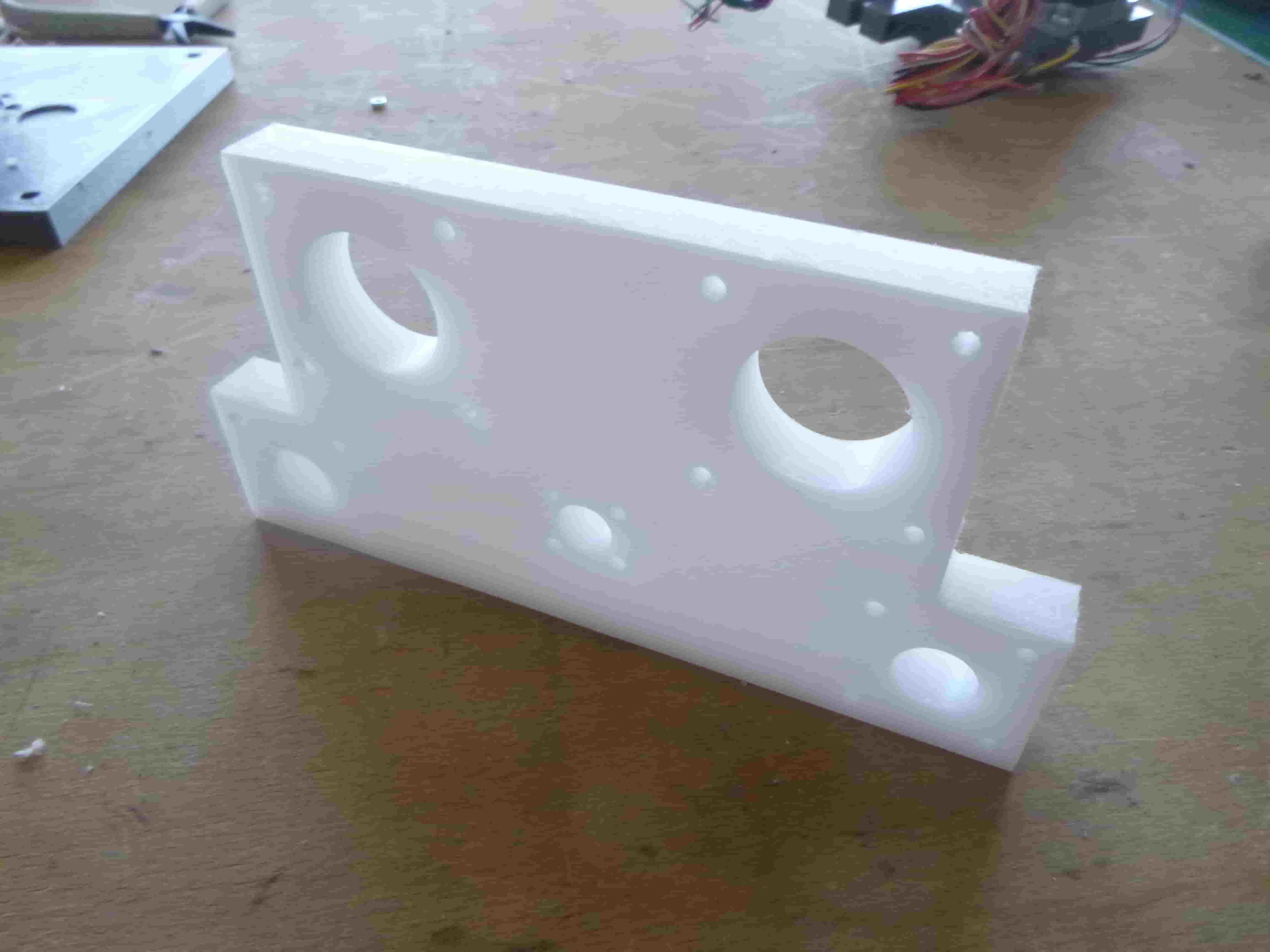
And here is the bottom piece milled and installed:
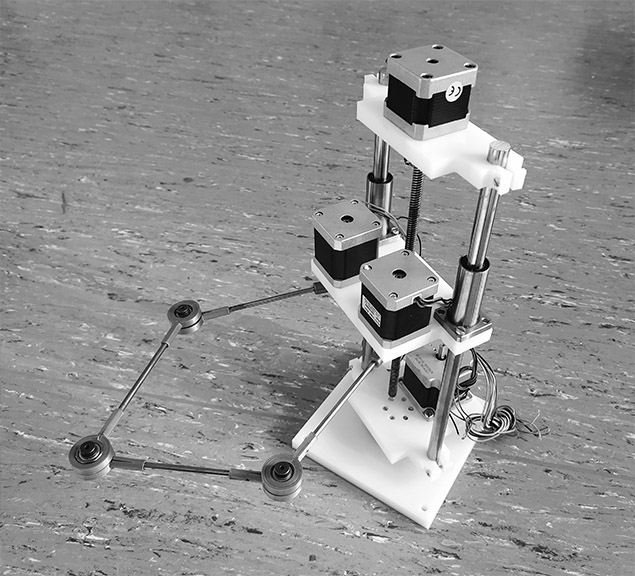
The fully milled rebuilt SCARA bot with a mounting base as well !:
Individual Assignment: Electronic instruments cupboard 3D Design
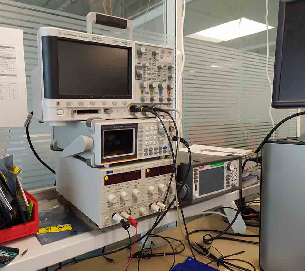
I would like to design a larger object which helps organize my electronic instruments. They are currently in an unwieldy pile :
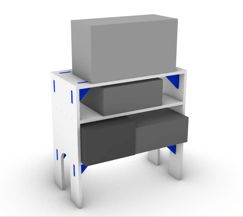
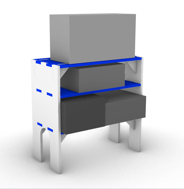
The idea is to use 12mm HPDE in two colors (blue and white) to make a cupboard on feet :
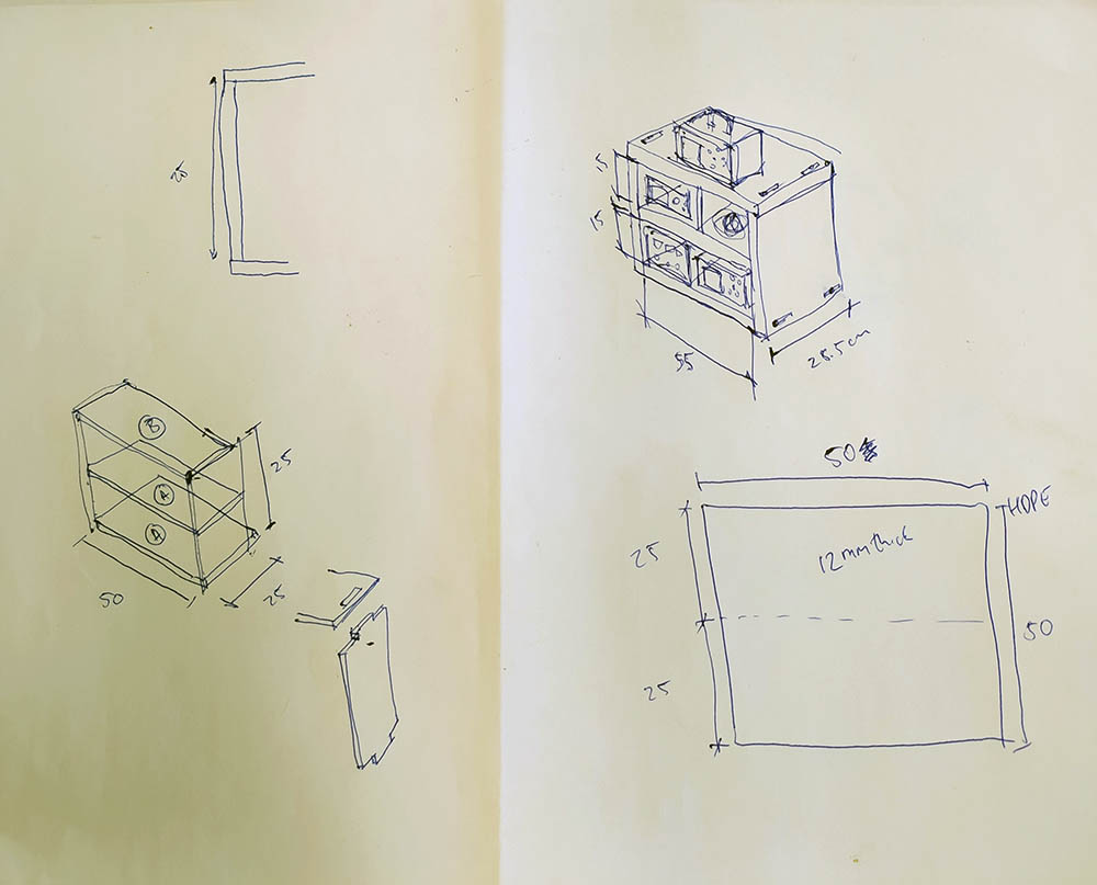
Here is the Rhino model :
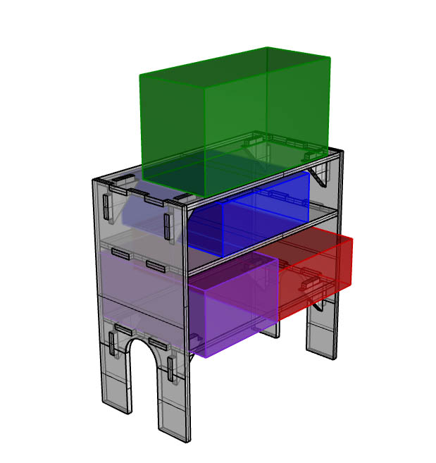
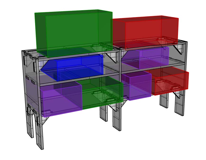
And some experiments with the color scheme:
The design could be modular and thereby be more in the scale of squared meters required for this week:
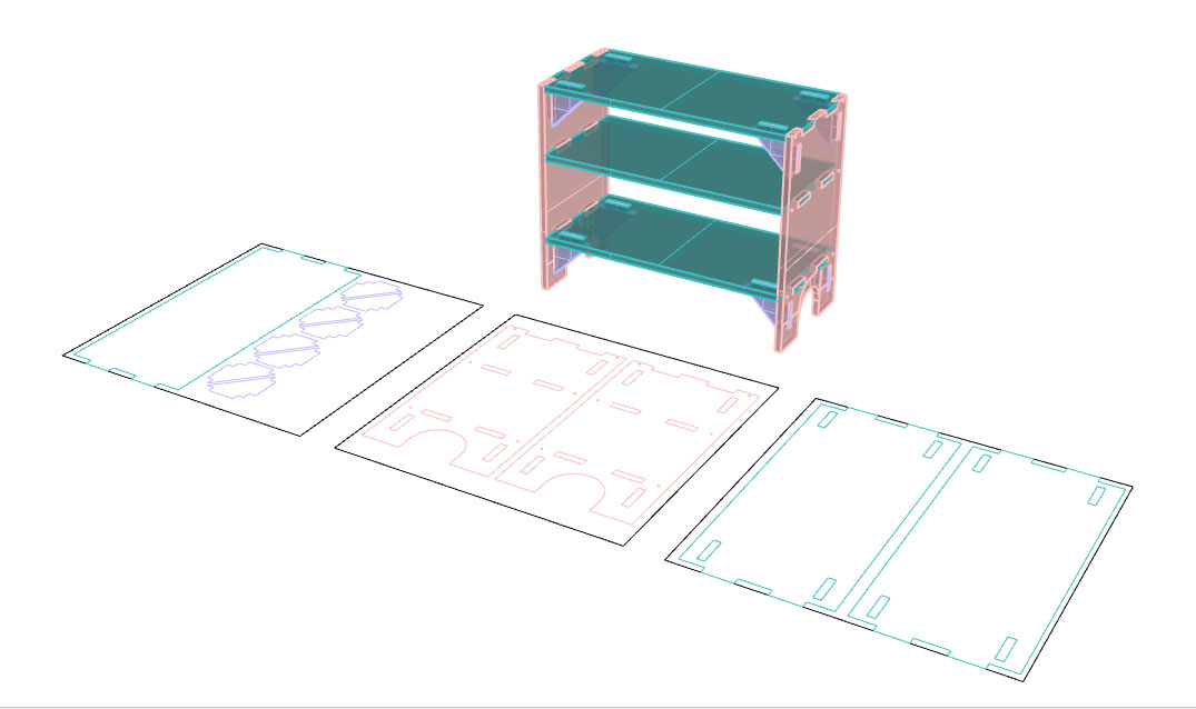
Here are the lines for milling :
Individual Assignment: Electronic instruments cupboard Milling
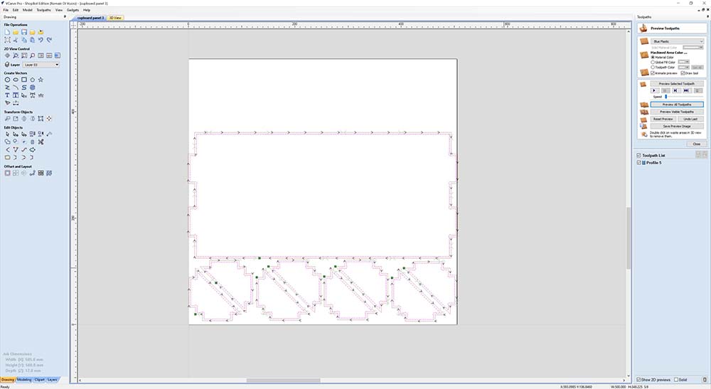
Here I’m preparing the lines in Vcarve using a 1/4” end mill. I’m using 12mm HDPE and each sheet is 50cmx50cm.
The most important thing to remember is to make dog bones if you want straight angles inside pockets !
Panel 1:
Panel 2:
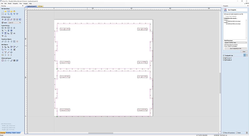
Panel 3:
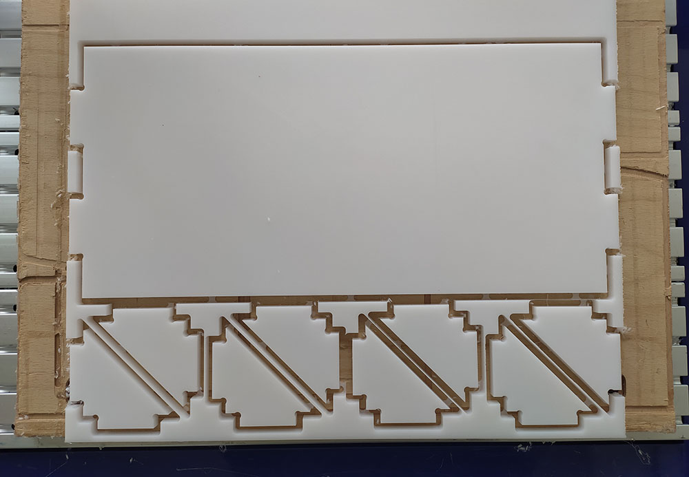
Here are the final panels cut:
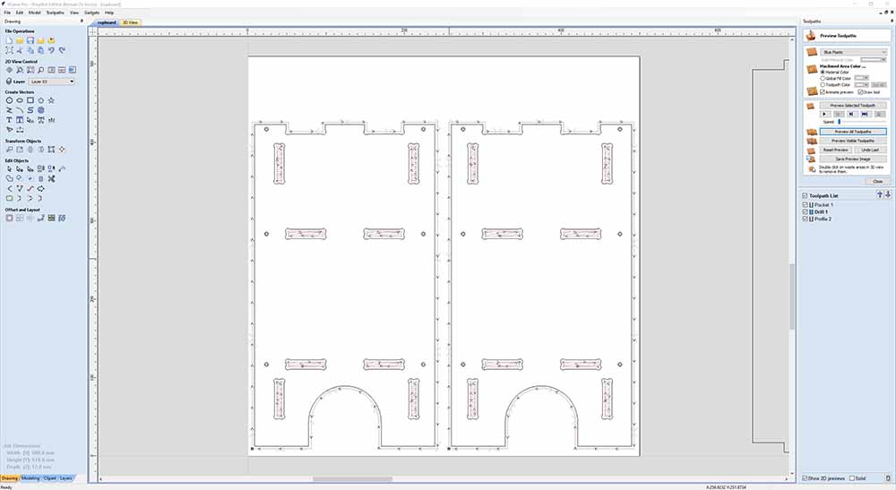
Panel 1:
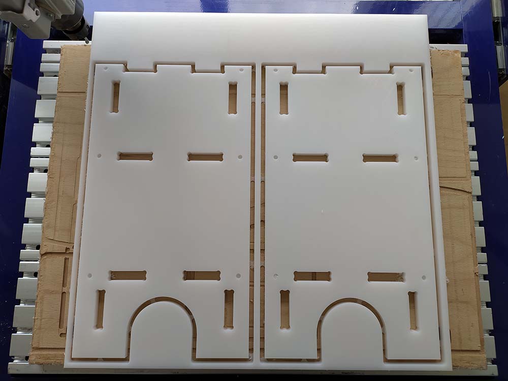
Panel 2:
Panel 3:
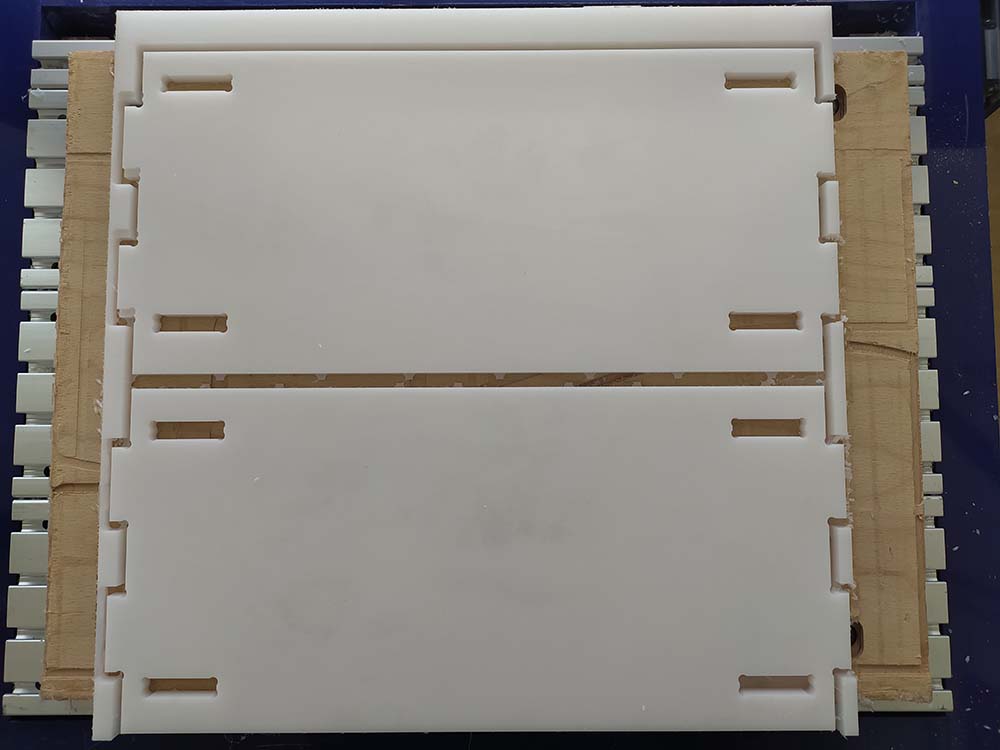
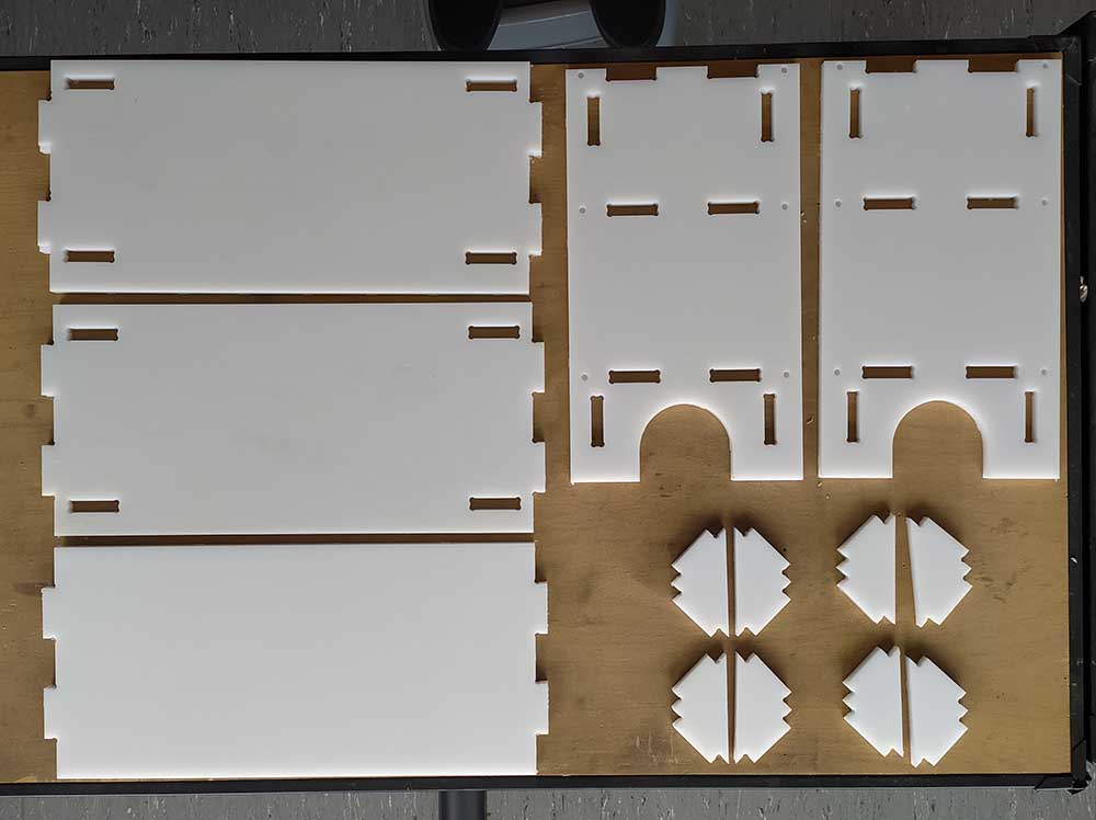
Here are all the parts cleaned up and tabs removed:
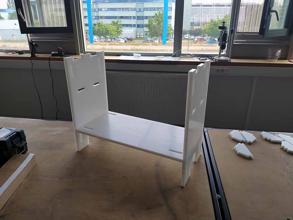
Here I’m assembling:
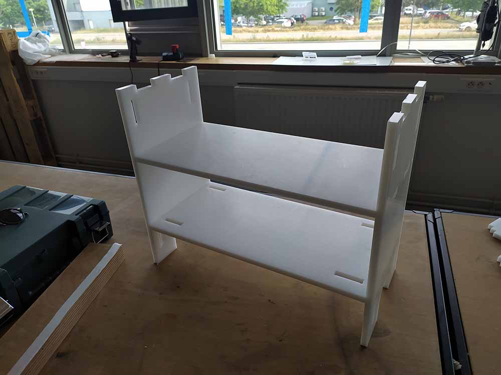
Second level:
Third level:
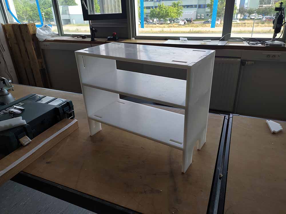
And here is the final result !
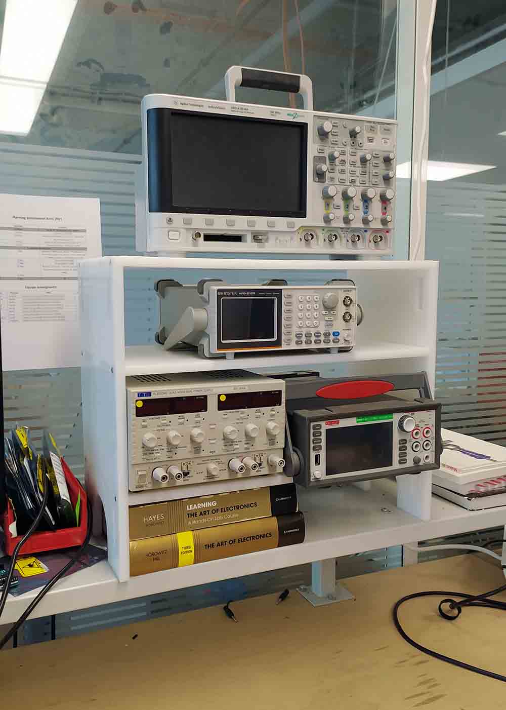
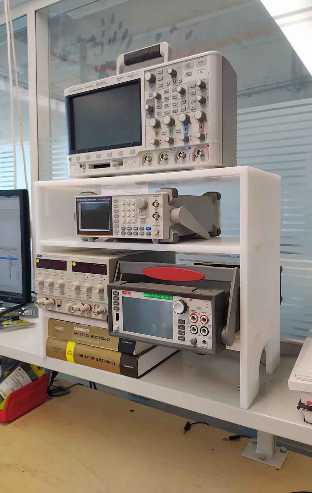
In terms of things to improve the triangle parts were too hard to insert but the bolts and press fit seem to be holding things alright for the moment.