3. Computer controlled cutting
Homework:
Group assignment:
characterize your lasercutter’s focus, power, speed, rate, kerf, joint clearance and types.
Individual assignment:
cut something on the vinylcutter design, lasercut, and document a parametric construction kit, accounting for the lasercutter kerf, which can be assembled in multiple ways, and for extra credit include elements that aren’t flat.
Here is the STL and Grasshopper files to generate any terrain from:
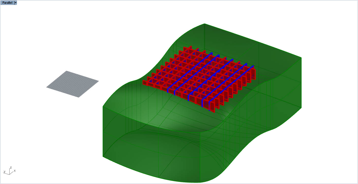
(Array the X and Y slat to fill the grid)
(MeshBooleanDifference the volume against the slats to have your final form)
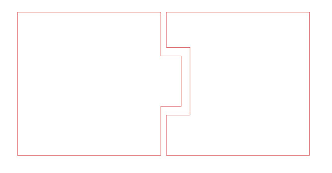
Here is just the lines to be cut on the lasercutter :
Here’s the logo I cut out on the vinyl cutter:
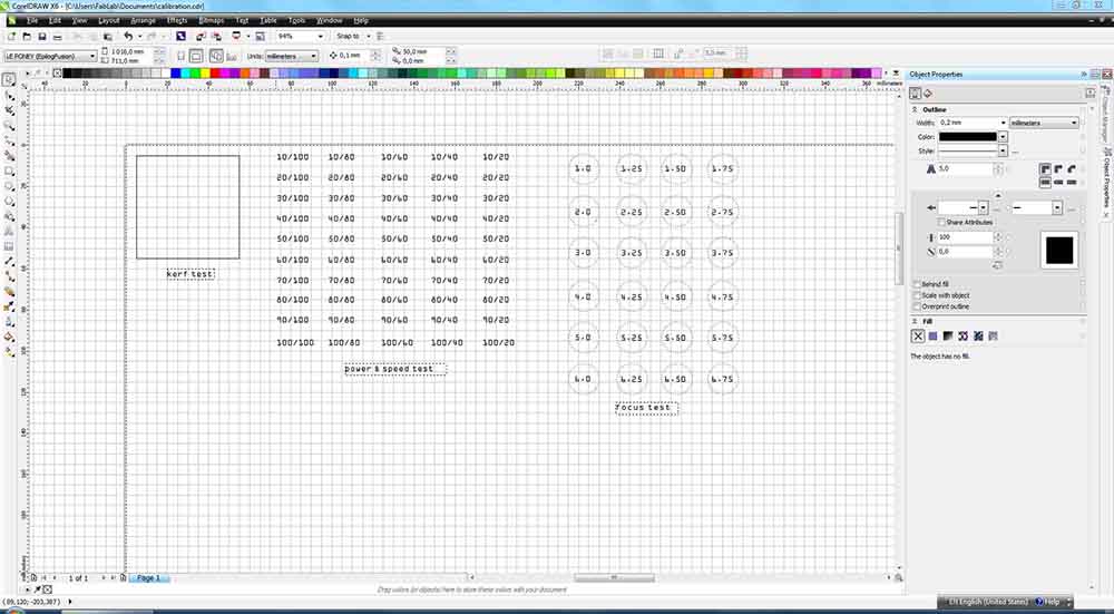
Here’s the calibration file I made to test the lasercutter:
+++++++++++++++++++++++++++++++++++++++++++++++++++++++++++++++++++++++++++++++++++++++++++++++++++++++++++++++++++++++++++++++++++++++++++++++++++++++++++++++++++++++++++++++++++++++
Research
This LamiFold technique is well documented in this article:
https://www.researchgate.net/publication/344612547_LamiFold_Fabricating_Objects_with_Integrated_Mechanisms_Using_a_Laser_cutter_Lamination_Workflow
Essentially an entire workflow involving lasercuttable mechanical primitives for various functional joints, sliders, hinges, etc. allowing for designers to make more complex 3D forms with the lasercutter in software. The technique involves selectively laser cutting and subsequently gluing stacks of certain kinds of sheet material. Using Fusion 360, they created a complete environment for designing, simulating and outputting cuttable files. The demonstration projects show that the method is versatile and drastically expands the possibilities of making 3D mechanisms with the lasercutter.
Parametric construction kit development
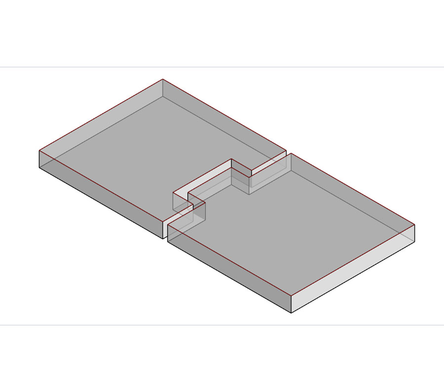
For my parametric construction kit I’m going to make the 3D surface of my Video Synth interface out of thin cardboard.
Getting familiar with automation and parametric modeling in Rhino 3D
Rhino is not a parametric modeler but it does support Grasshopper which was designed for this purpose. I started off trying to parametrically model in Rhino using Blocks and the Record History feature.
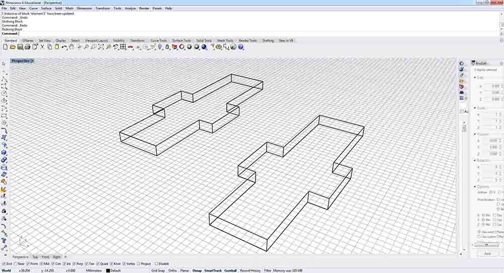
To make a block in Rhino you create a form and then use the Block command. Thereafter, each copy of the block you make will be linked to the original block. To edit this original block you need only modify a single copy of the block, by first using the Explode command, and then oversave the block with the original name after selecting the basepoint.
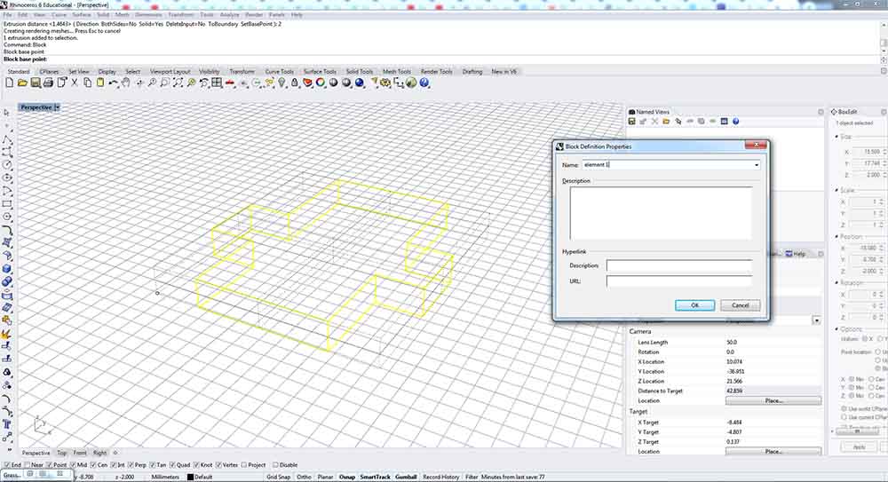
Here I exploded the block and then stretched it using the gumball feature. I then saved the deformed original block with the same name as the original block.
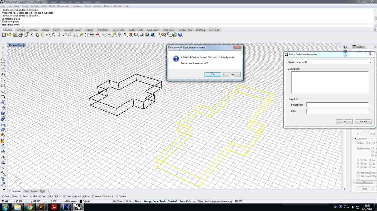
The result is that the new block replaces the old block by using the base point to orient itself.
Here I am experimenting with Record History. First I created a simple joint starting with three overlapping rectangles, selecting everything and triming lines with the Trim command. I also used the Offset command to create a line which was a precise distance away from another.
I then turned on the Record History button on the bottom panel and, using the Extrude command, turned my lines into a 3D form.
Now whenever I edit the parent lines from which the 3D extrusion was made, the 3D model updates itself based on the changes made.
Going back to how I made my prototype for the oceanique video synth, I want to have a parametrically defined 3D wave that I can construct and reconstruct in different ways.
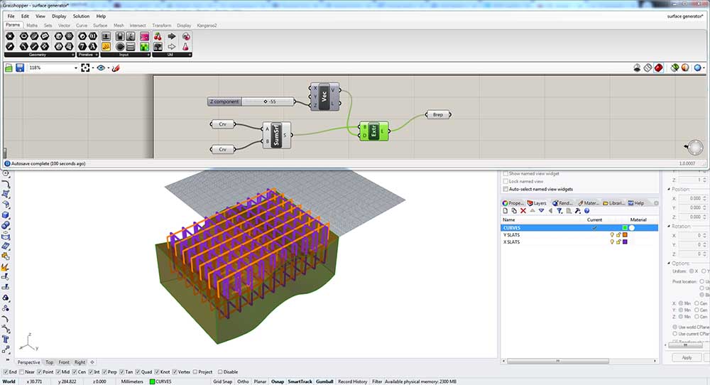
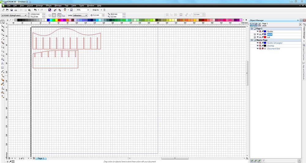
I start by making a loft between two modifiable curves. I create a curve object in Grasshopper and associate the curves in Rhino by clicking on them.
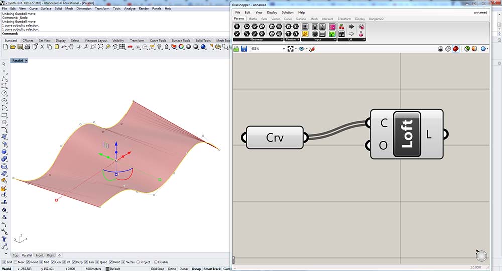
I next extract points from the lofted surface…
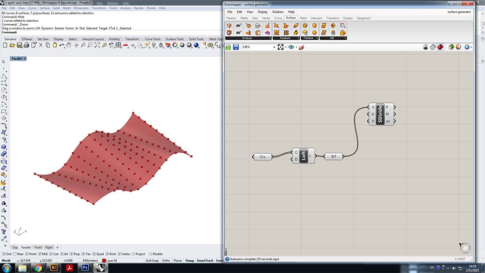
…and use those points to reconstruct contour lines which follow the initial surface.

Here I am extruding these lines into BREPs.
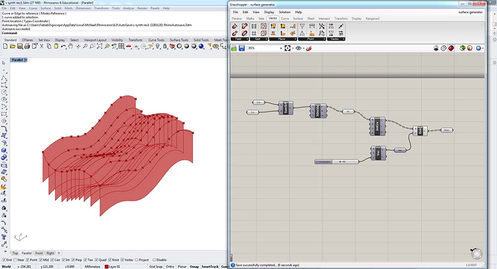
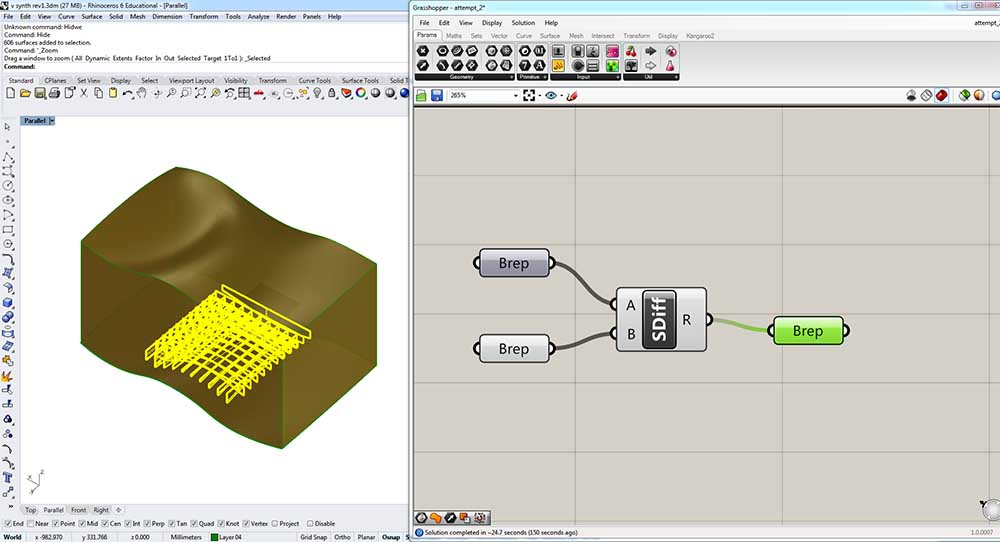
Here I am trying to boolean difference the terrain profiles with a volume but I am having trouble getting Grasshopper to cut surfaces with a volume.
I couldn’t figure out why I couldn’t interpolate the lines in other axes and how it decided to interpolate them all in the same axis. I went looking for similar projects online and found this: https://discourse.mcneel.com/t/creating-a-series-of-curves-through-points/50697
Using the same principle of making a BREP, subdividing it, and then using those subdivisions to create contour lines, I ended up with this patch:
I am starting to realize how challenging this would be to generate a series of 2D profiles with subtractions deriving from this model. I think there is a more efficient strategy using Record History and Blocks which will have same output which I will now try.
Here I am attempting to first manually reproduce the effect I’m going for.
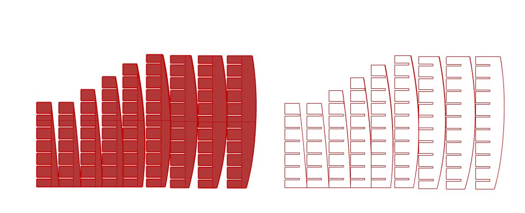
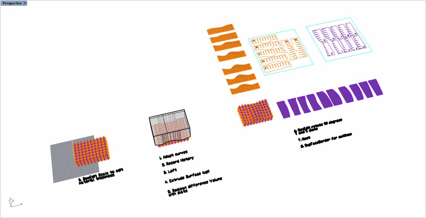
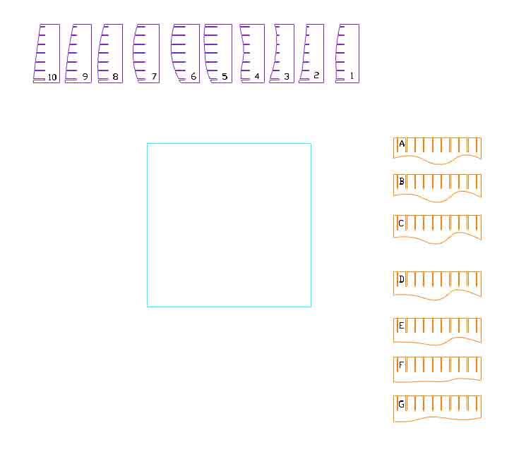
I first used the Array command to make a grid of panels.
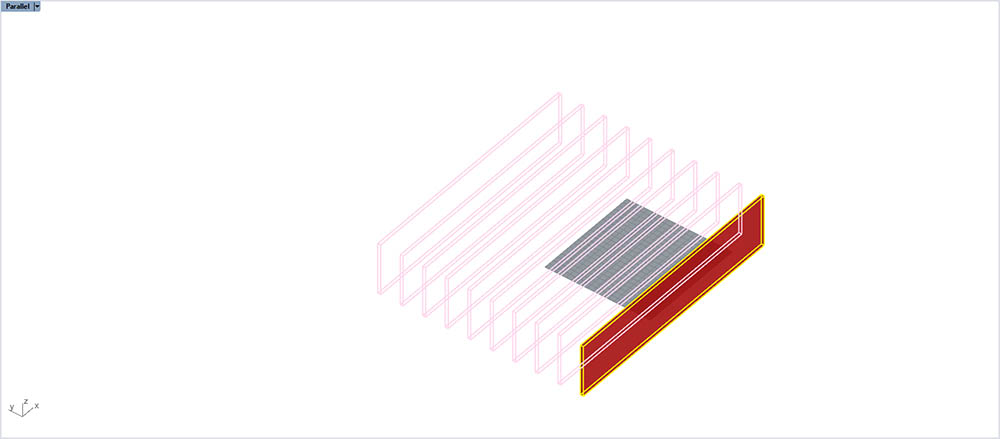
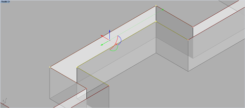
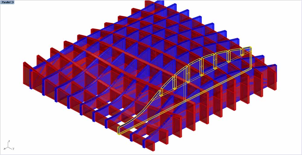
I then subtracted the top half of one axis array and the bottom half of the the other axis array to make an interlocking array:
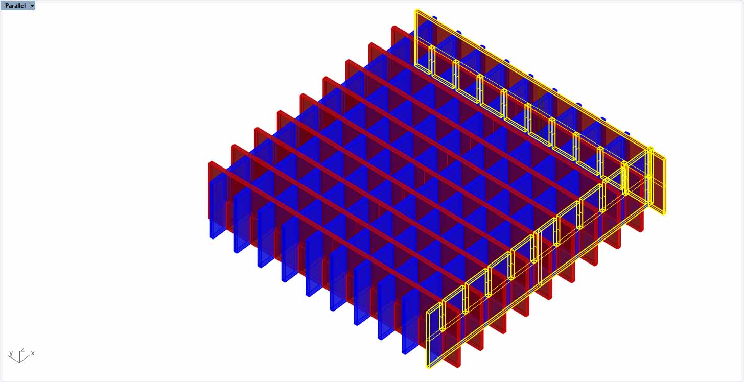
This is how the X and Y pieces will slot into one another:
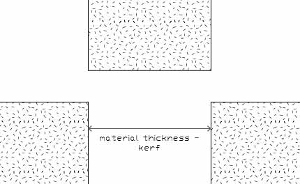
The width of the notch will be the material thickness minus the kerf for a perfect fit I think.
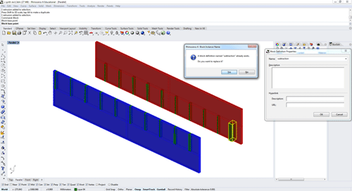
Here is how I am using a block as a subtraction parameter which, in turn updates the various blocks X and Y. This will effectively act as the kerf parameter.
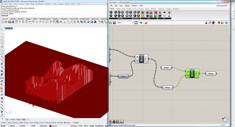
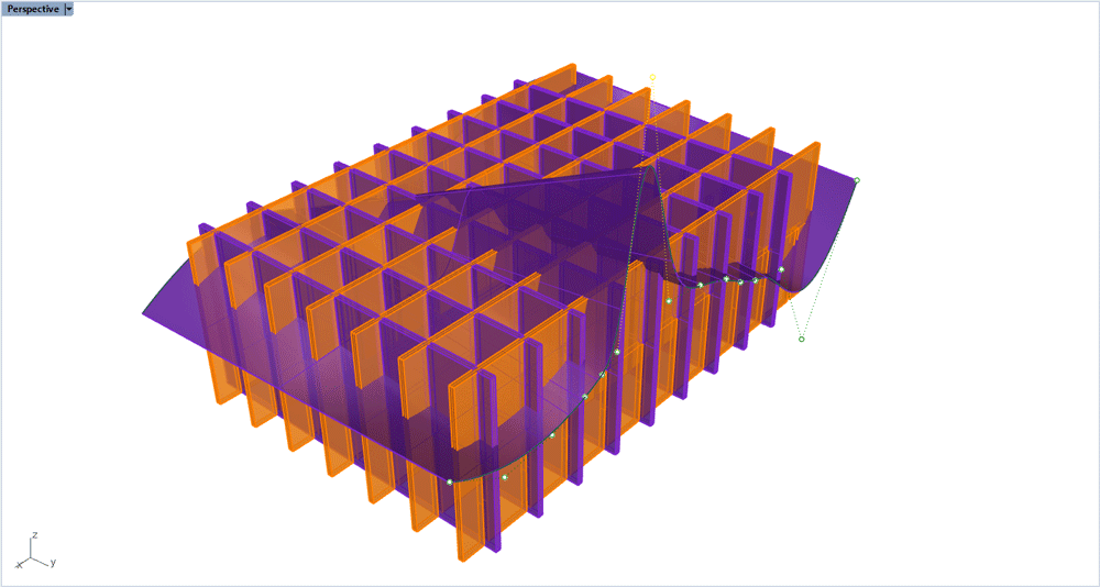
Using the grasshopper script I can regenerate the loft from the base curves and then re-boolean them against this set of base panels:
This would be the result (but this one cuts too deep so I would need to adjust the height of the panels):
All that’s left to make this process parametric and painless is to create a Rhino script that automates this process of changing the kerf subtraction, and regenerating the loft and booleaning it against the panels, flattening the panels and projecting the lines so they can be easily cut on the laser cutter. The idea here is to start from predefined axis parts, extrude them based on a thickness (kerf) in X and Y, construct a surface with a loft from two curves, and then subract the whole thing. I think this is a good compromise in terms of automation versus manually clicking around.
Here is a grasshopper boolean difference with pre-existing volumes:
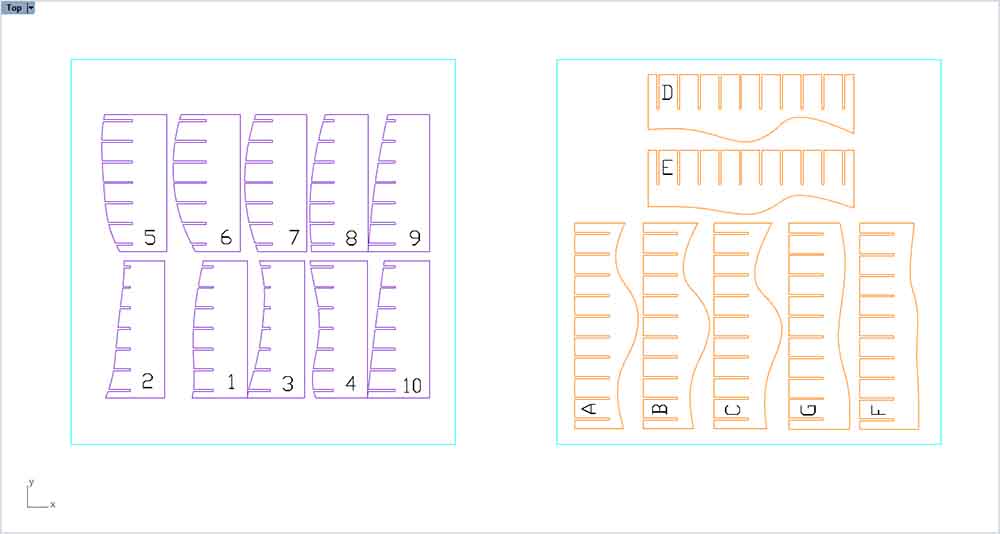
I am using the Block Edit command to flip the slats 90 degrees and place them such that they can be converted into lines next:
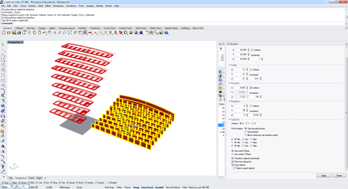
Now I am using Rhino Macros to automate the changing of the camera angle to Top, and then the execution of the command Make2D:
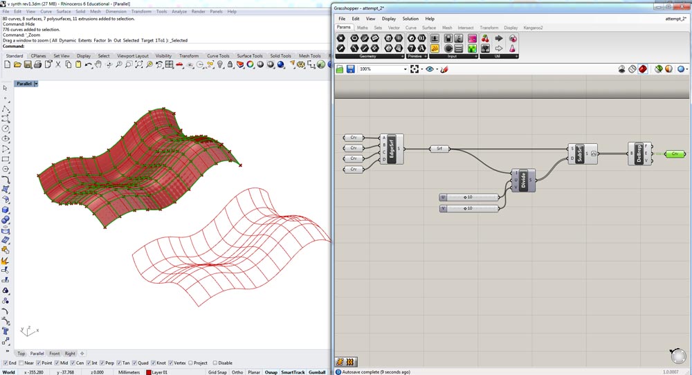
I now have a couple of ways of making a parametrically updating surface. The first is with Record History:
With Grasshopper I have a working parametric surface now that regenerates the slats based on the surface :
It creates a solid object which then needs to be sliced using the Contour command.
I also created a Rhino 3D construction kit with instructions as I work towards automizing this entirely with Grasshopper:
+++++++++++++++++++++++++++++++++++++++++++++++++++++++++++++++++++++++++++++++++++++++++++++++++++++++++++++++++++++++++++++++++++++++++++++++++++++++++++++++++++++++++++++++++++++++
Final parametric construction kit
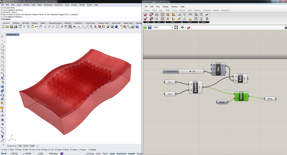
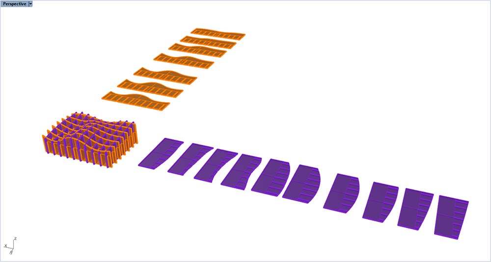
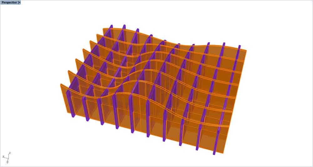
Here is what the final Rhino and Grasshopper parametric terrain modeler looks like (files available at the top of the page):
Changing the control points of the two curves will automatically refresh the surface loft and extrusion. Once you have selected the volume you like you can right click and select Bake on the BREP subtraction volume form.
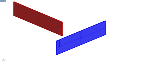
In Rhino, you just need to select your X and Y slats and BooleanDifference them against the Baked subtraction volume to end up with your slats to laser cut.
Here is the final result of subtraction:
+++++++++++++++++++++++++++++++++++++++++++++++++++++++++++++++++++++++++++++++++++++++++++++++++++++++++++++++++++++++++++++++++++++++++++++++++++++++++++++++++++++++++++++++++++++++
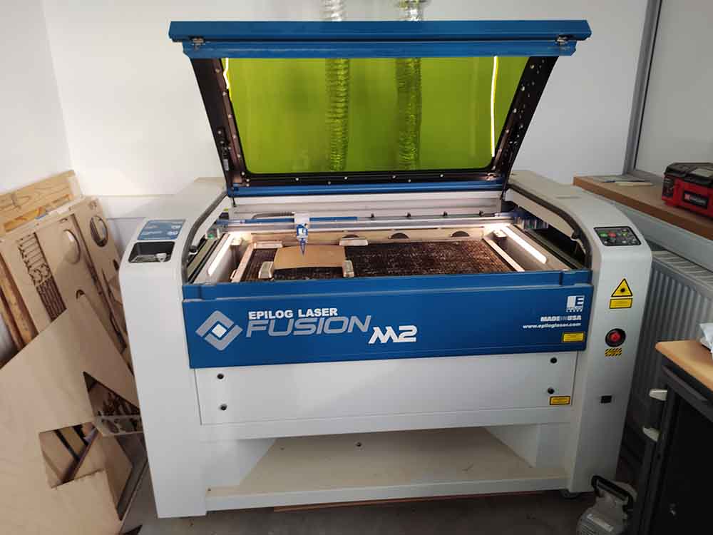
Lasercutting: Calibration
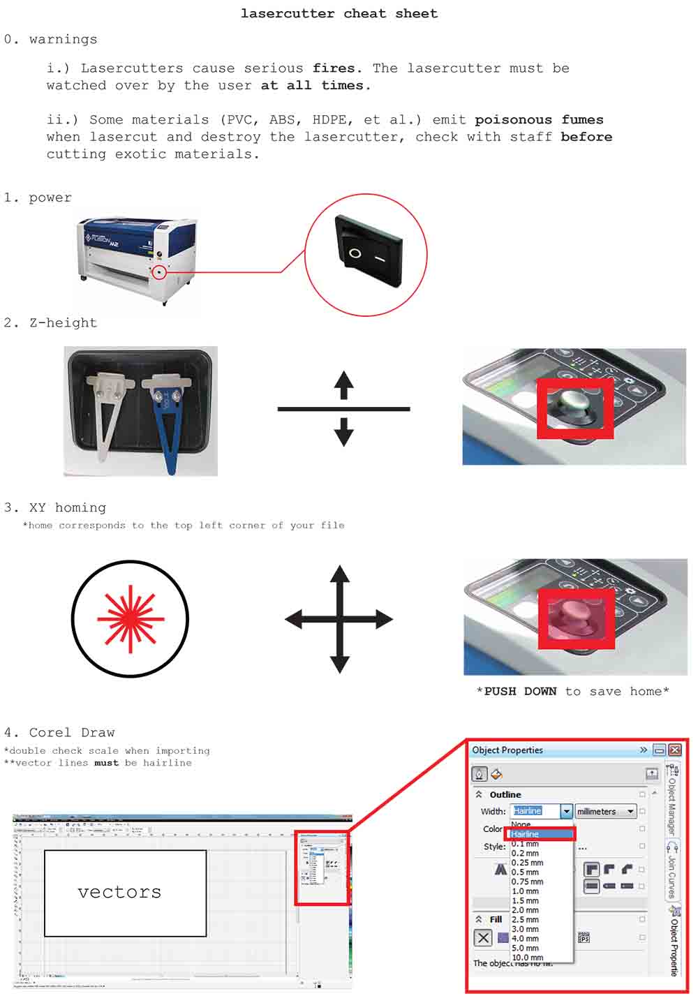
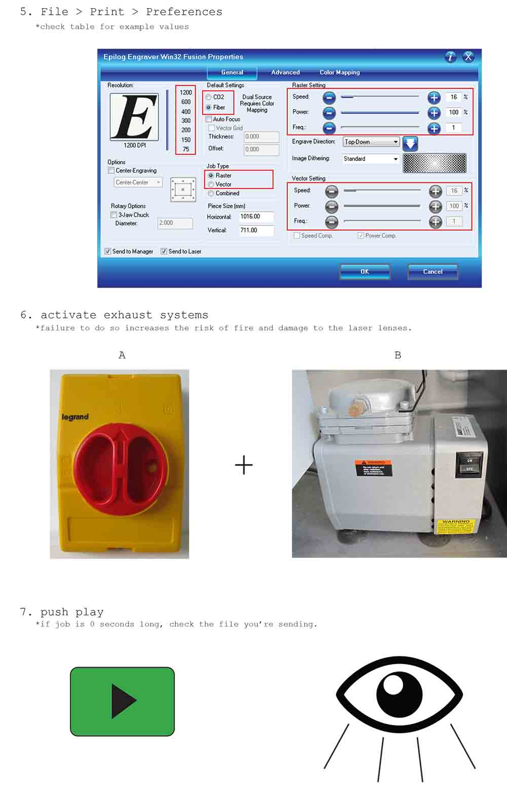
I put together a double-sided cheat sheet for our laser cutter specifying all the steps required to get a cut ready:
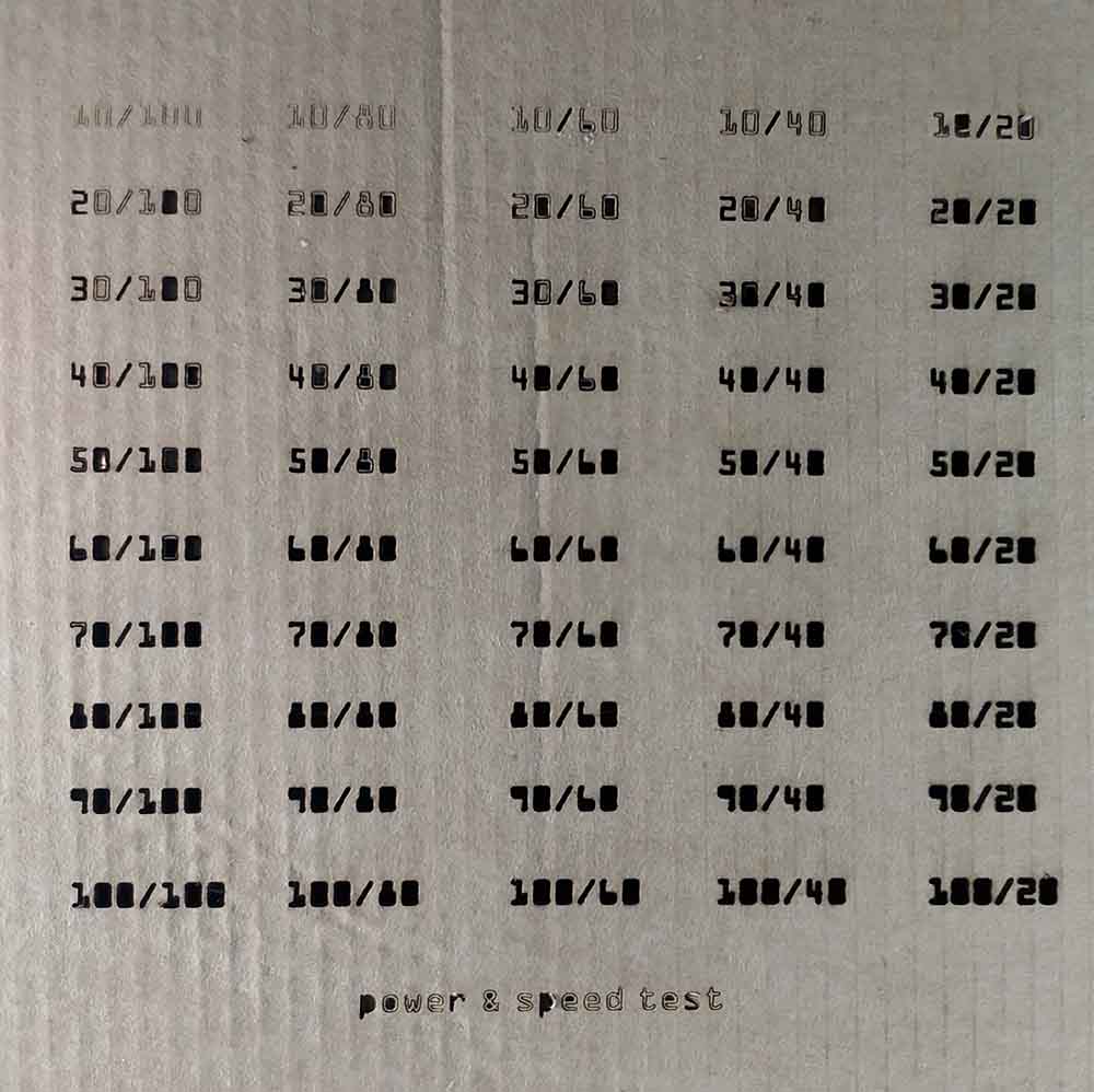
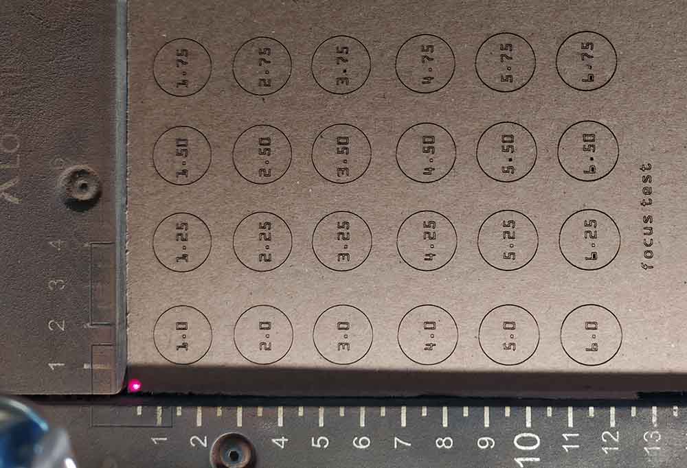
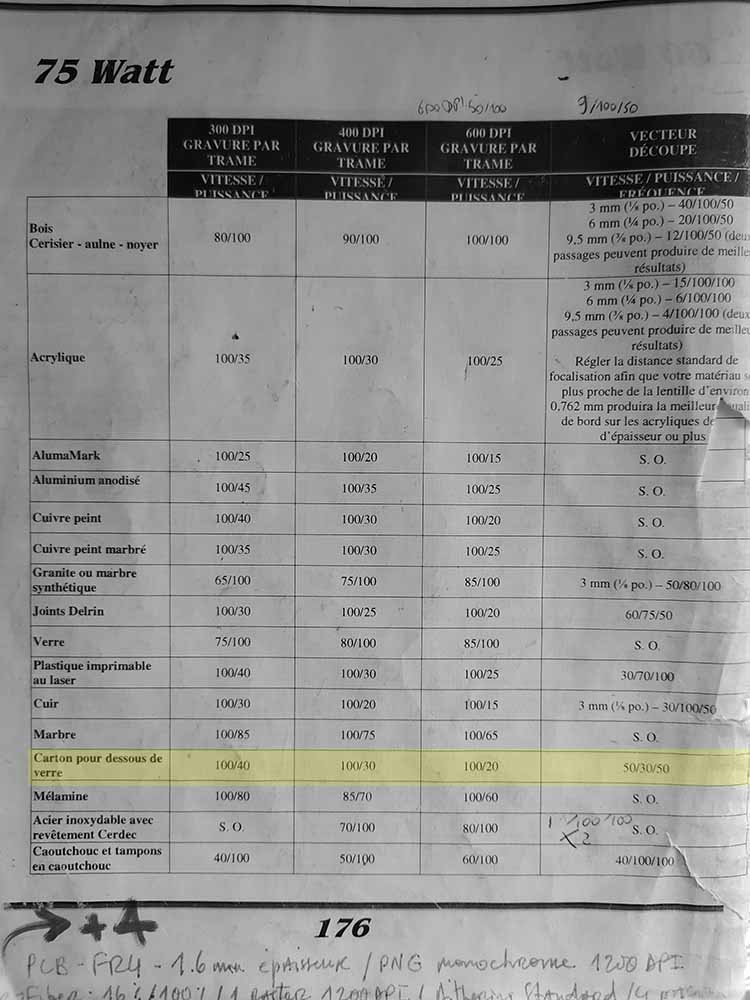
I also did some characterizing of the machine’s parameters. I was most interested in the different speed/power combinations, the effect of focus, and the size of the kerf for the 1.5mm thick cardboard I intended to use. Here is the calibration file I made (available at the top of the page) :
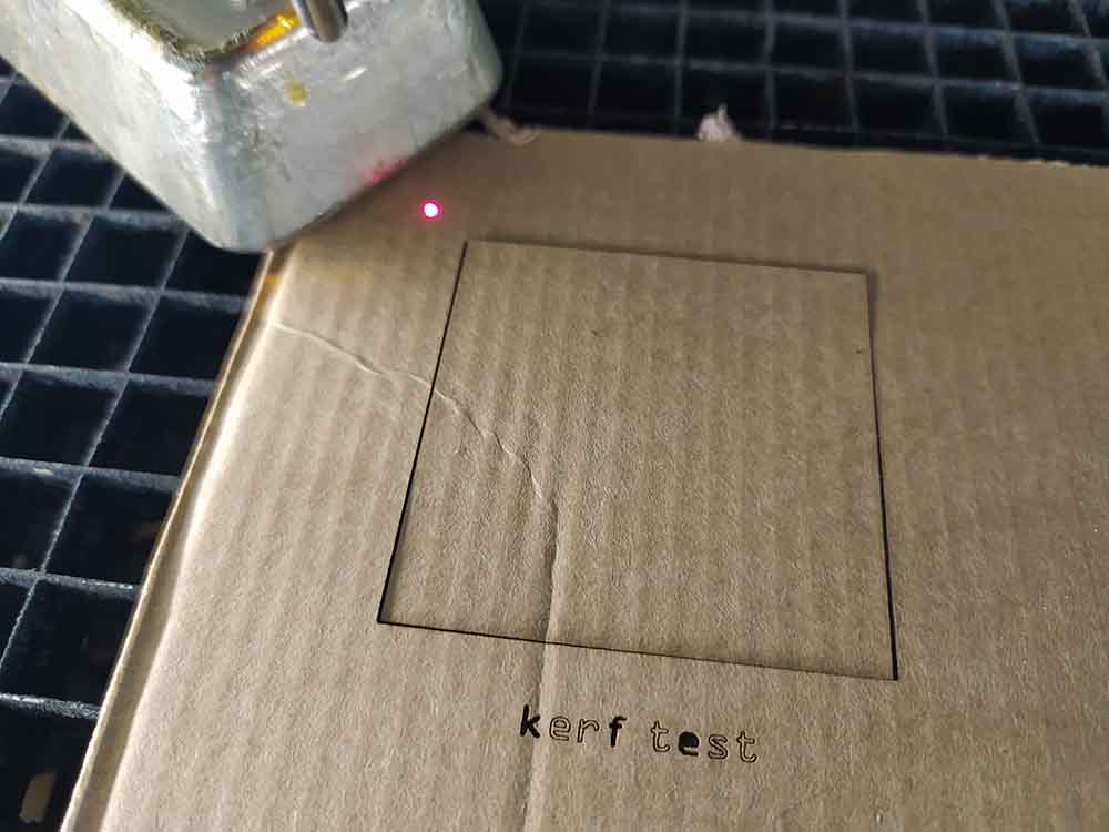
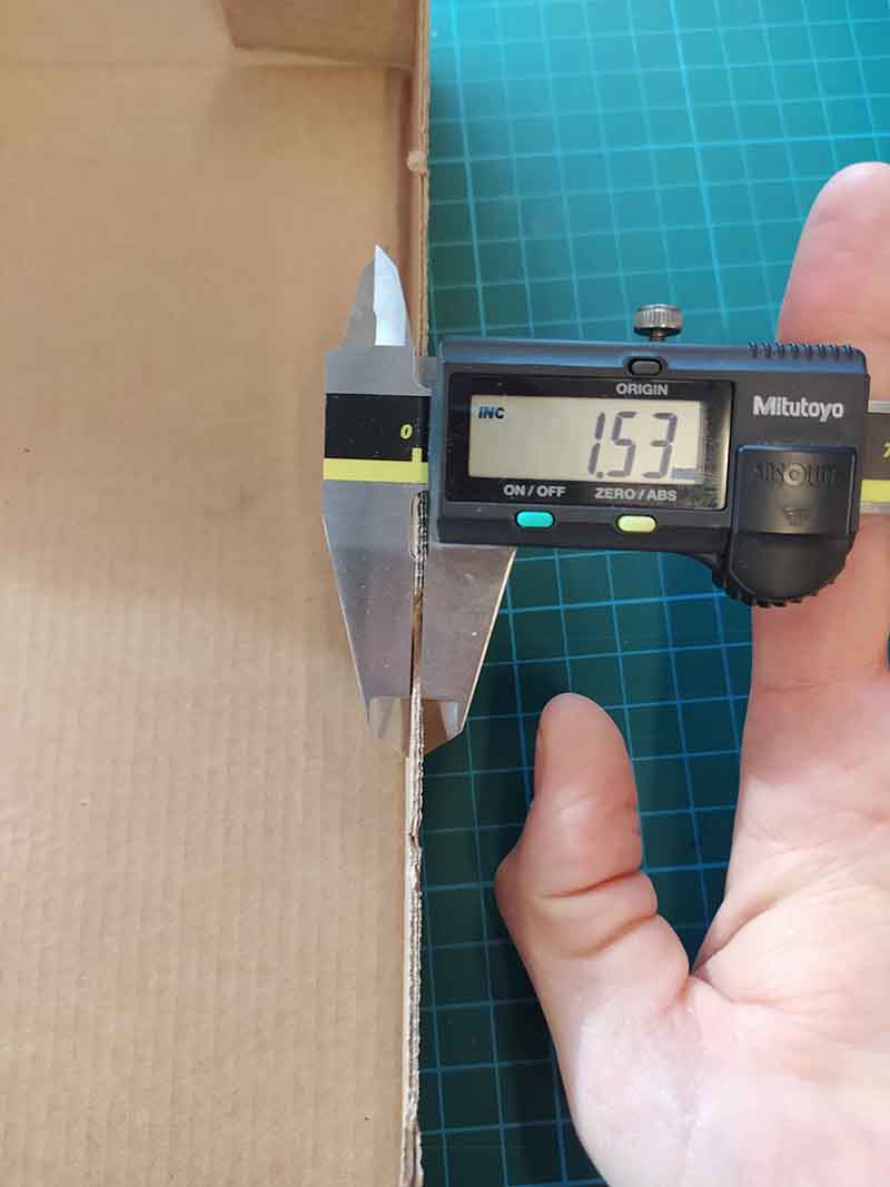
I cut out a square that is 15cmx15cm.
Here I measure the inside and outside dimensions of the square.
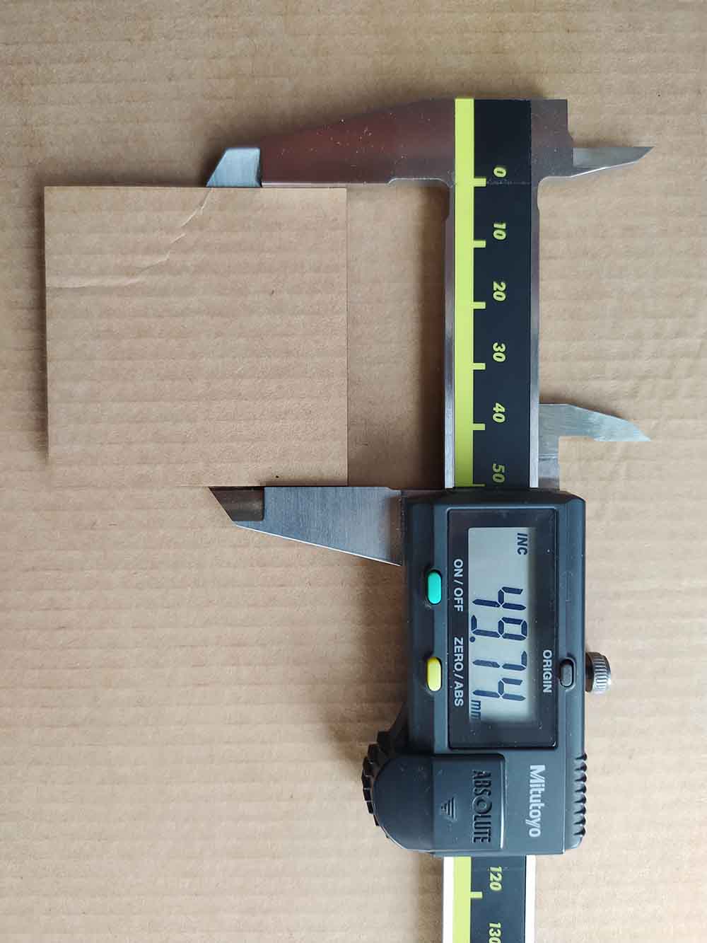
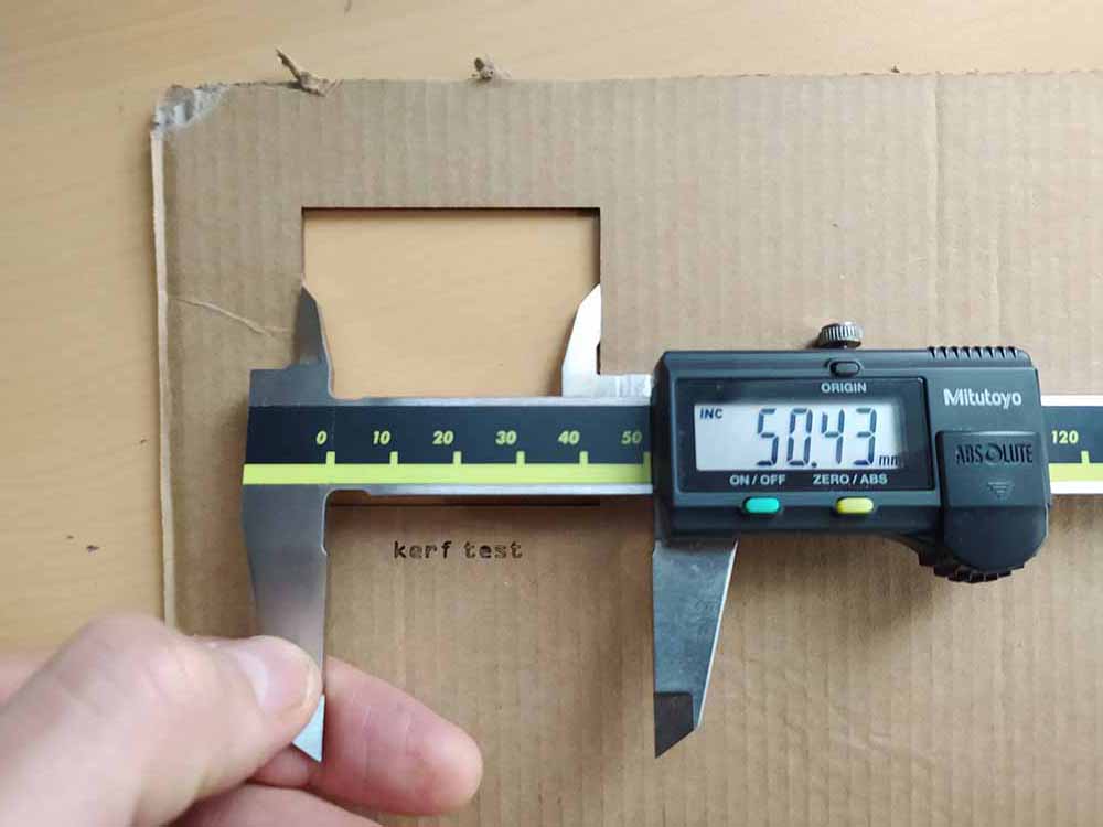
It looks like the kerf is around 0.5mm on this material.
I also (painstakingly) tested various combinations of power and speed which was enlightening:
A little less enlightening, but still cool to carry out, was my focus test. I was expecting there to be a big difference but then I remembered my experience finely adjusting the focus is from working with the fiber laser on metal where focus really is crucial. It was at least interesting to see that the machine has a margin of atleast 6cm in Z and it will still mark text without significant blur. The measuring device than came with the lens sets the laser lens about 1.25cm away from the zero on the Epilog Fusion’s Z axis. However it is possible to notice a slight degradation in line quality starting after 3.5cm.
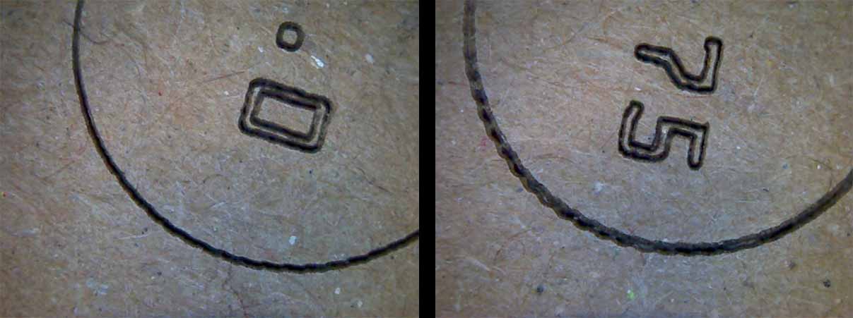
Looking closer with our USB microscope though it is clear that there is a difference between the 1.0cm focus (left) and the 6.75cm (right) focus:
+++++++++++++++++++++++++++++++++++++++++++++++++++++++++++++++++++++++++++++++++++++++++++++++++++++++++++++++++++++++++++++++++++++++++++++++++++++++++++++++++++++++++++++++++++++++
Lasercutting: 3D form
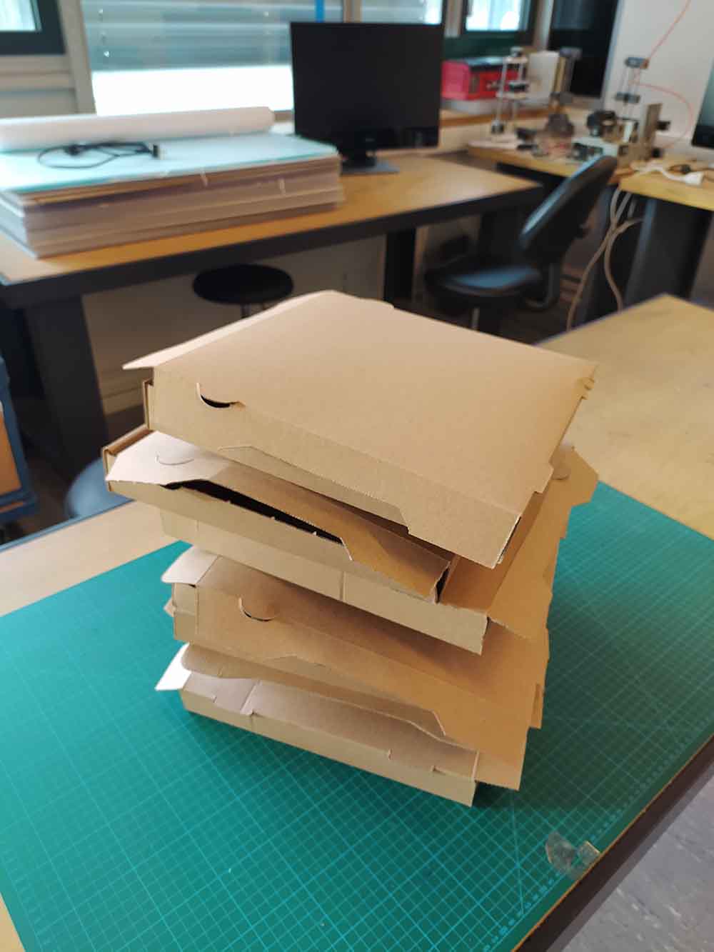
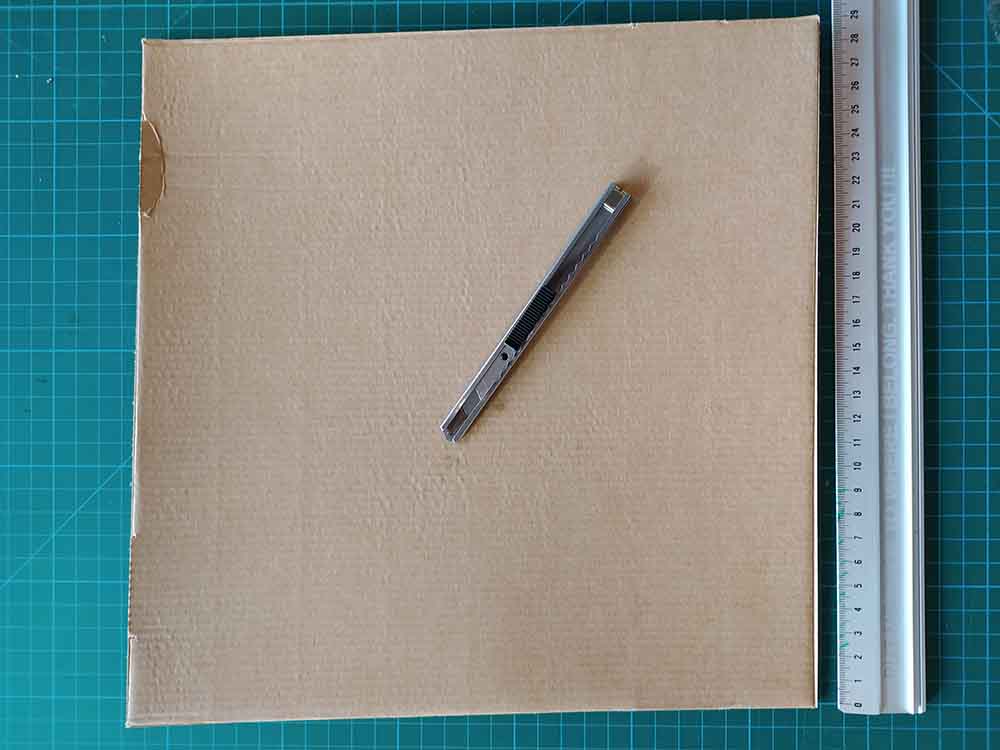
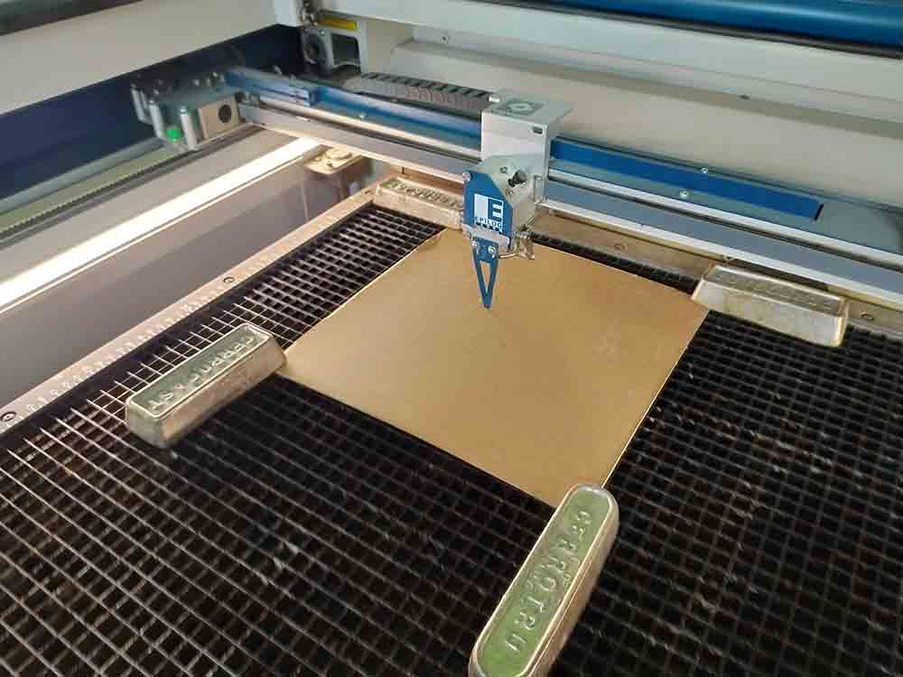
I am using old pizza boxes with a cuttable area of 28x28cms and a thickness of 1.5mm
Using my digital calipers it looks like the thickness is around 1.5mm
Post exacto knife cutting:
Importing my DXF vector file from Rhino 3D:
Here I am checking some recommended power and speed settings from the manual.
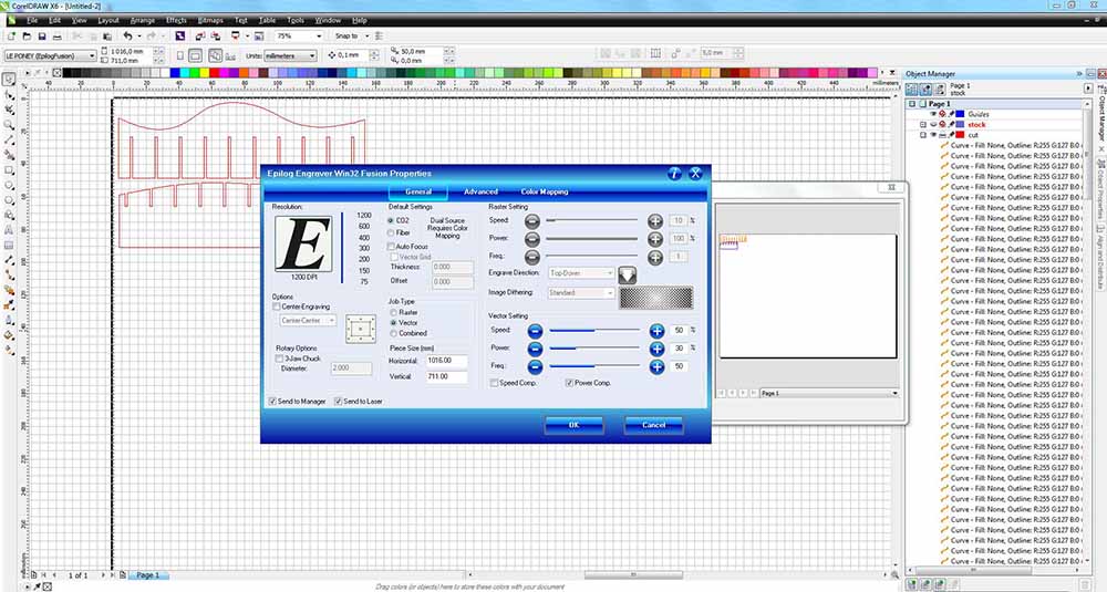
I drew the stock size, made sure my lines were Hairline, set the Epilog Laser dialog box up to cut Vectors with 50 speed, 30 power at 50 Hz frequency.
Here I put lead weights on top of the cardboard to keep it flat and homed the machine to the top left corner of the material.
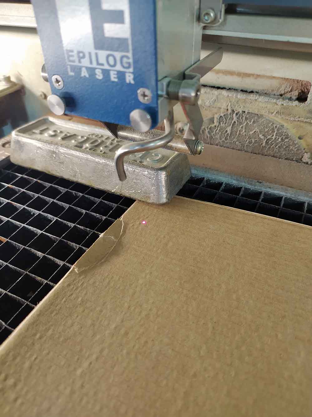
I set the Z height for the CO2 laser lining up the bottom of the blue focal instrument with the top surface of the material.
Here I’m setting the XY to the top left corner of the stock.
Watching the magic happen:
It worked on the first try with the setting I chose.
The press fit was nice also (The kerf is adding the necessary space - I am cutting the material size without modification here). I think I’m ready to go and produce the full object.
+++++++++++++++++++++++++++++++++++++++++++++++++++++++++++++++++++++++++++++++++++++++++++++++++++++++++++++++++++++++++++++++++++++++++++++++++++++++++++++++++++++++++++++++++++++++
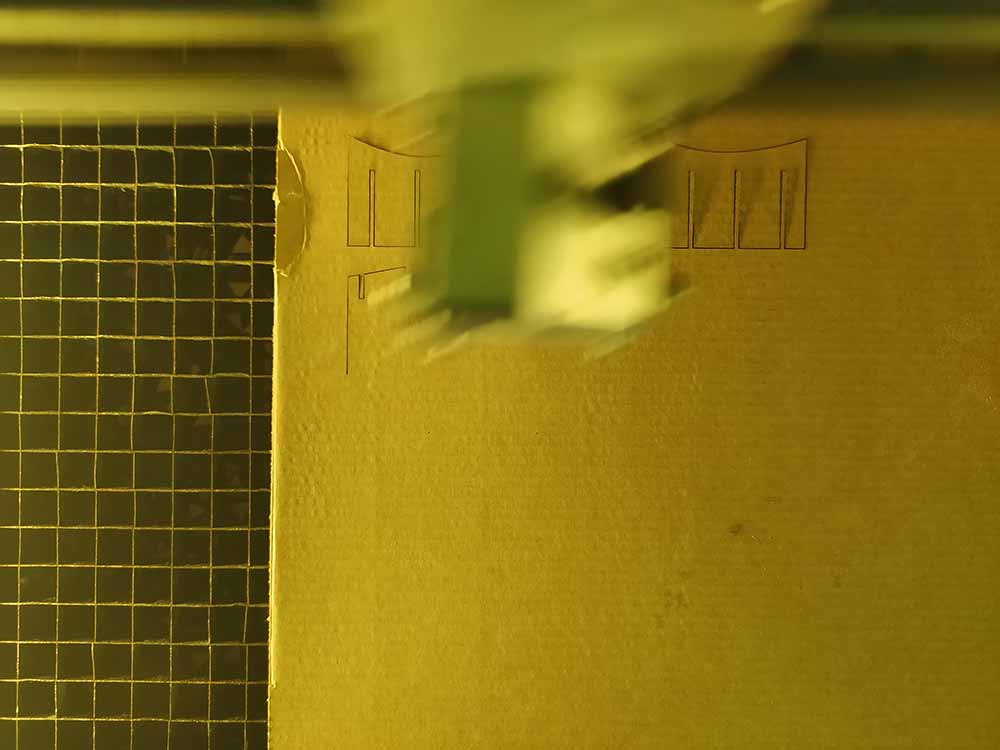
Lasercutting the full prototype
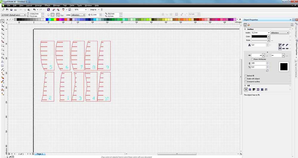
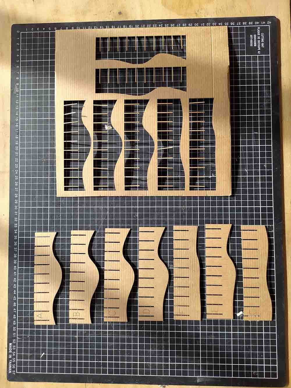
Here is me preparing the lasercut file:
I am using the DuplicateFaceBorder command (the Make 2D actually creates two top curves, because of the curvy surface subtracting the volumes) to generate the outlines.
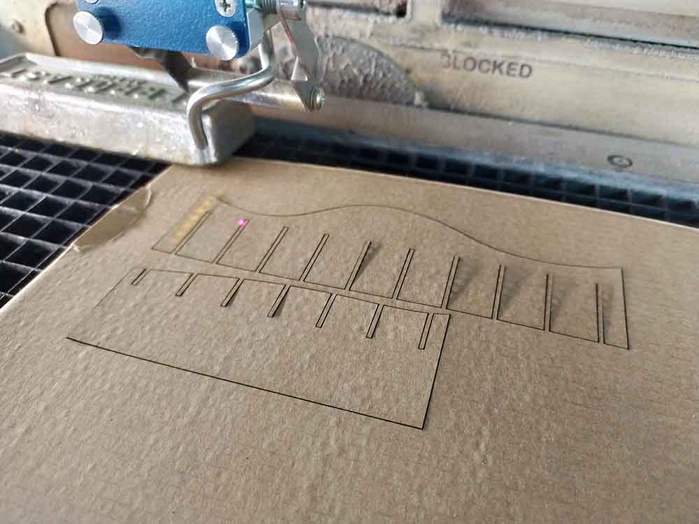
I’m not trying to hard to optimize the nesting because I’m using two old pizza boxes:
I put the text on a seperate layer for engraving here. I’m using Speed: 100, Power: 20 for engraving. For cutting Speed 50, Power: 30, Frequency: 50 and then a second pass with the engraving parameters.
I put the text on a seperate layer for engraving here. I’m using Speed: 100, Power: 20 for engraving. For cutting Speed 50, Power: 30, Frequency: 50 and then a second pass with the engraving parameters.
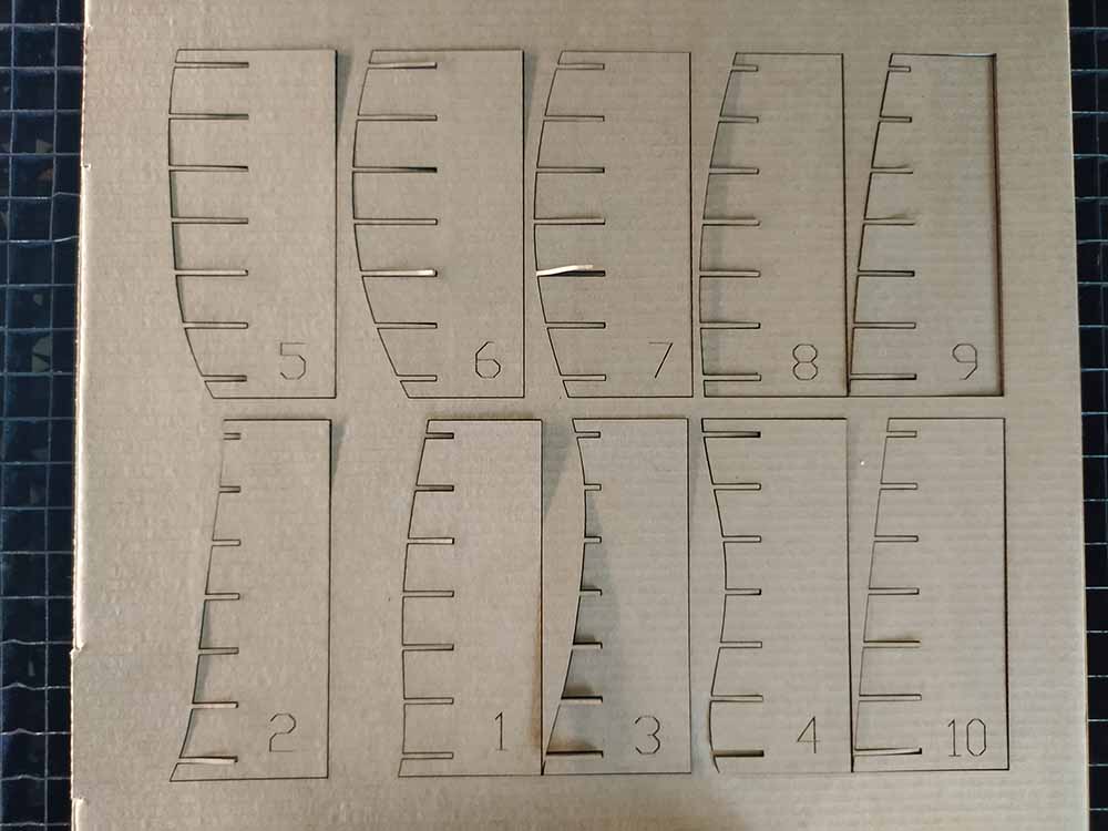
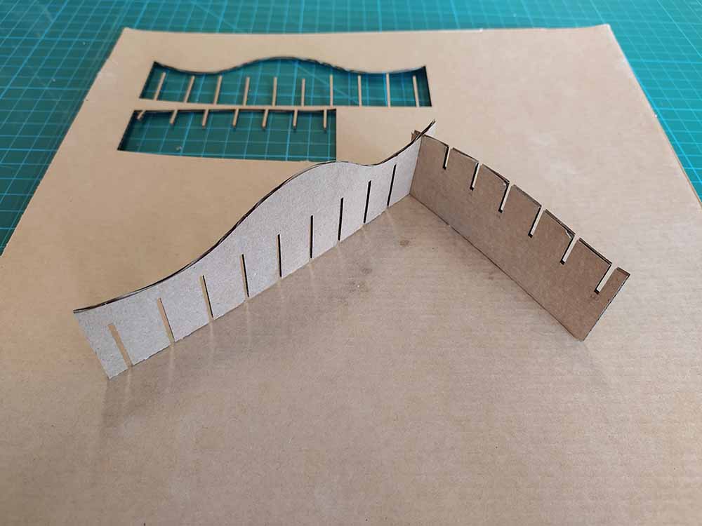
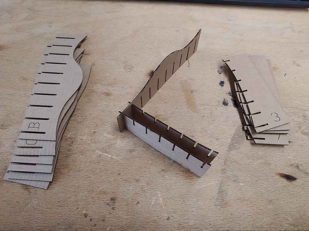
Here is the second set taken out from the board.
I assembled it wrong at first - but it does prove it’s reconfigurable!
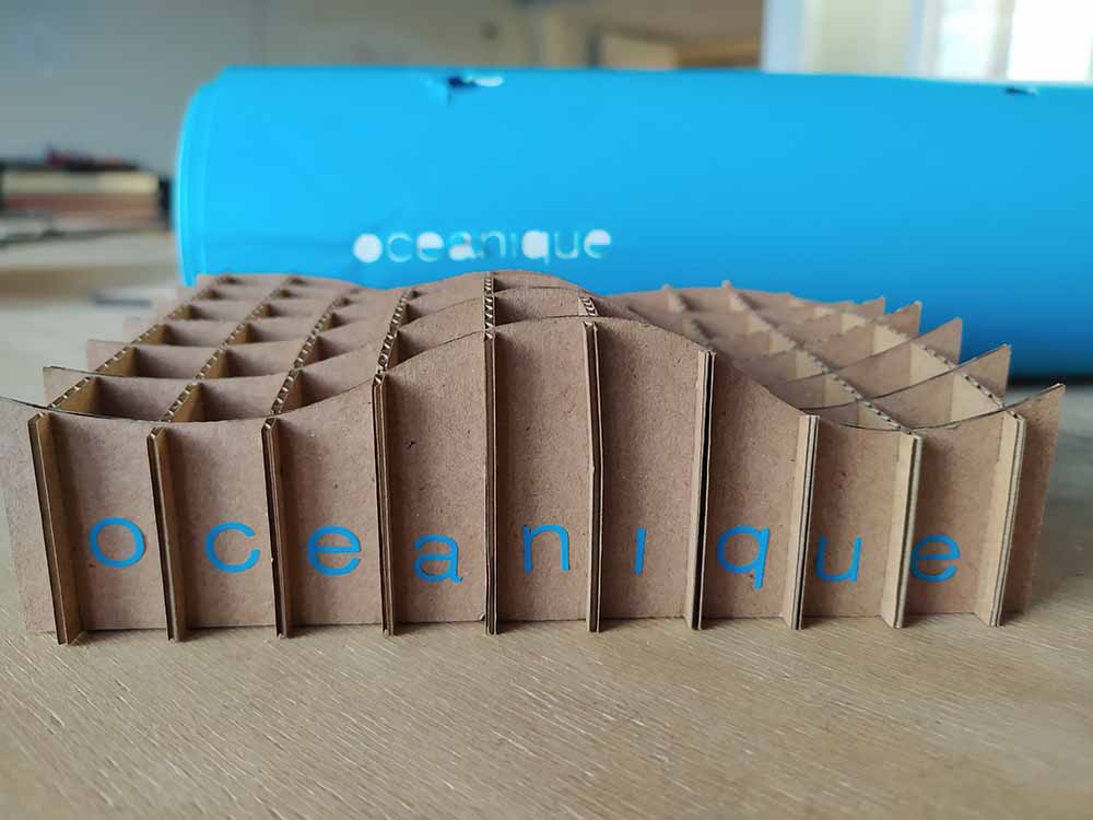
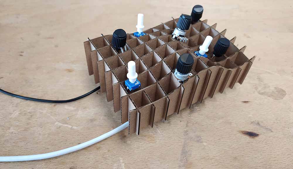
Here is the final object:
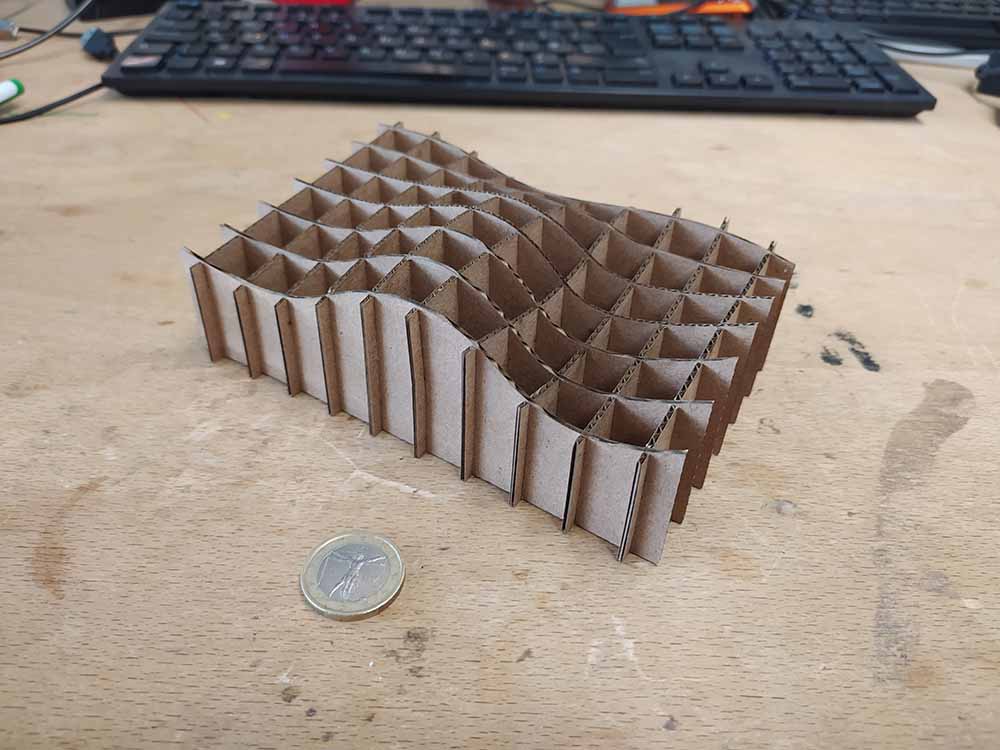
…compared to the digital:
…and with knobs and wires to simulate the final thing:
+++++++++++++++++++++++++++++++++++++++++++++++++++++++++++++++++++++++++++++++++++++++++++++++++++++++++++++++++++++++++++++++++++++++++++++++++++++++++++++++++++++++++++++++++++++++
Vinyl Cutting
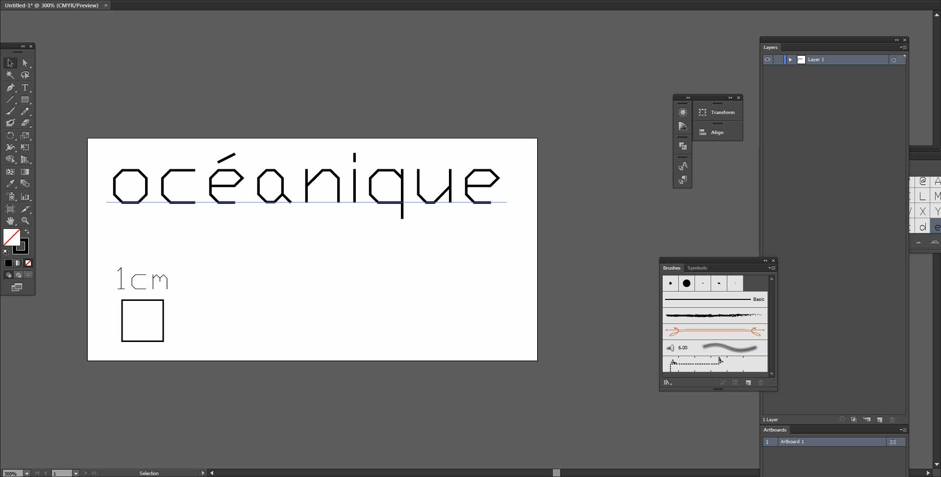
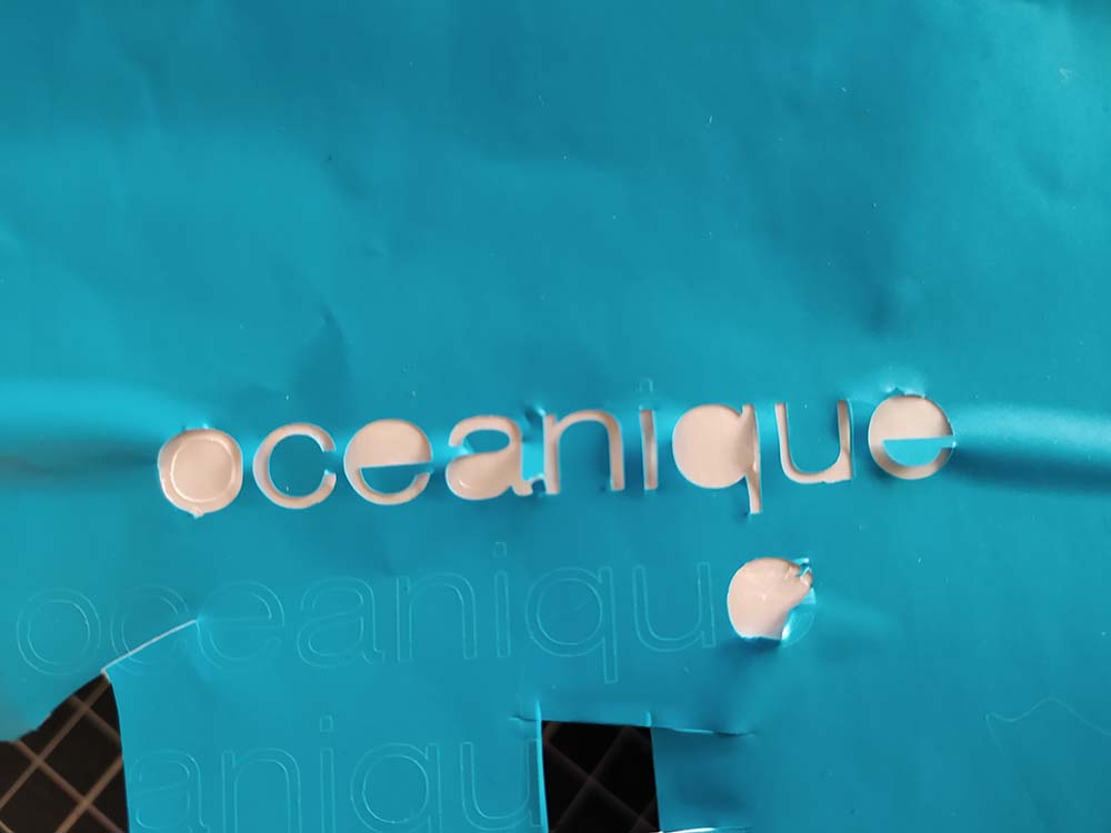
I’m going to cut out the letters oceanique for my synth prototype:
This file, in .AI, .SVG, or any other, proved to be an issue for Roland’s software.
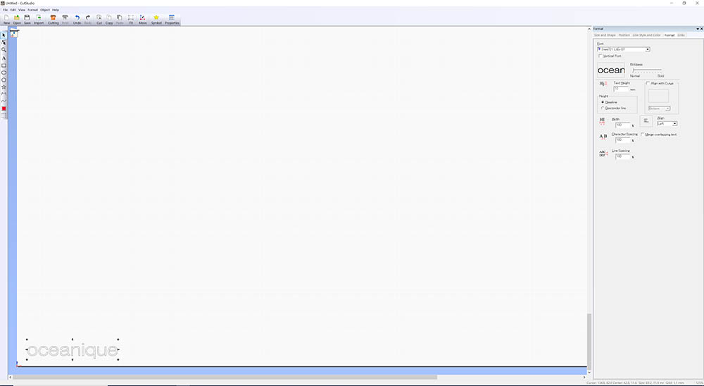
I recreated the text in a different font. Set the machine to place the text at the origin, and hit print.
Before actually printing I installed a roll of vinyl in the cutter making sure to lift the lever. I inspected several other materials and chose this one for the turquoise color. Because the surface that I’m attaching the vinyl to is not flat, I’m going to free form it. This might also let me test having the text not totally even (wave-like).
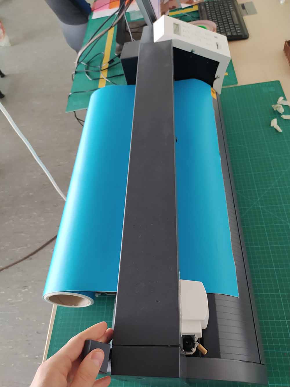
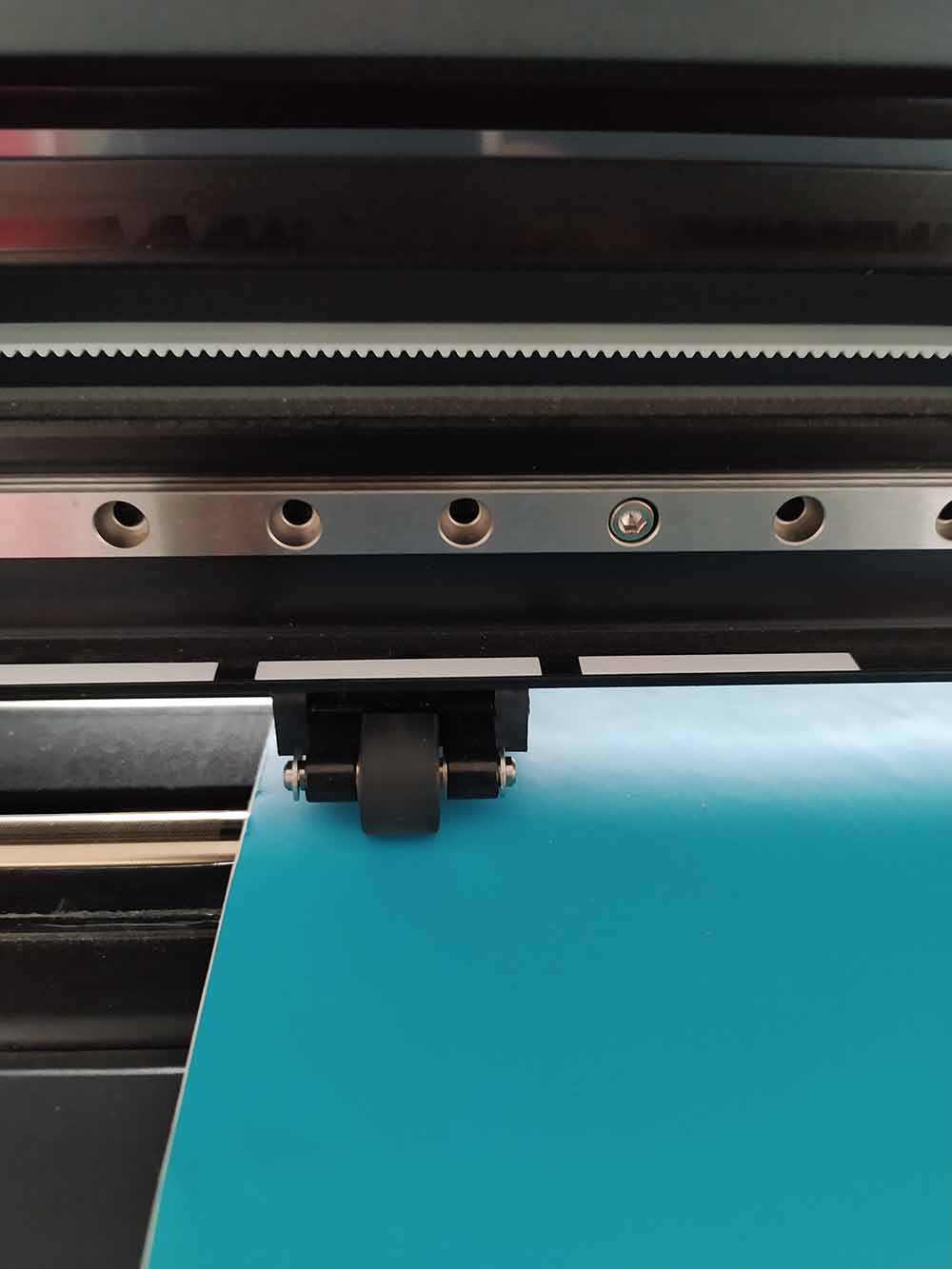
I moved the tracking wheel to the edge of the material and let the machine sense the edge after turning on.
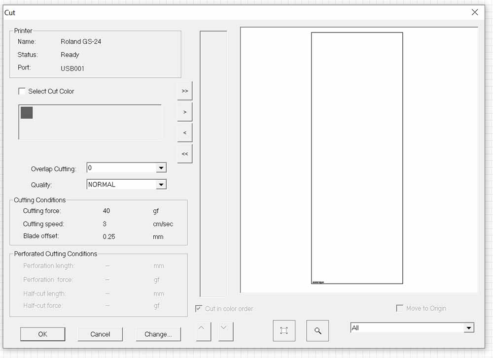
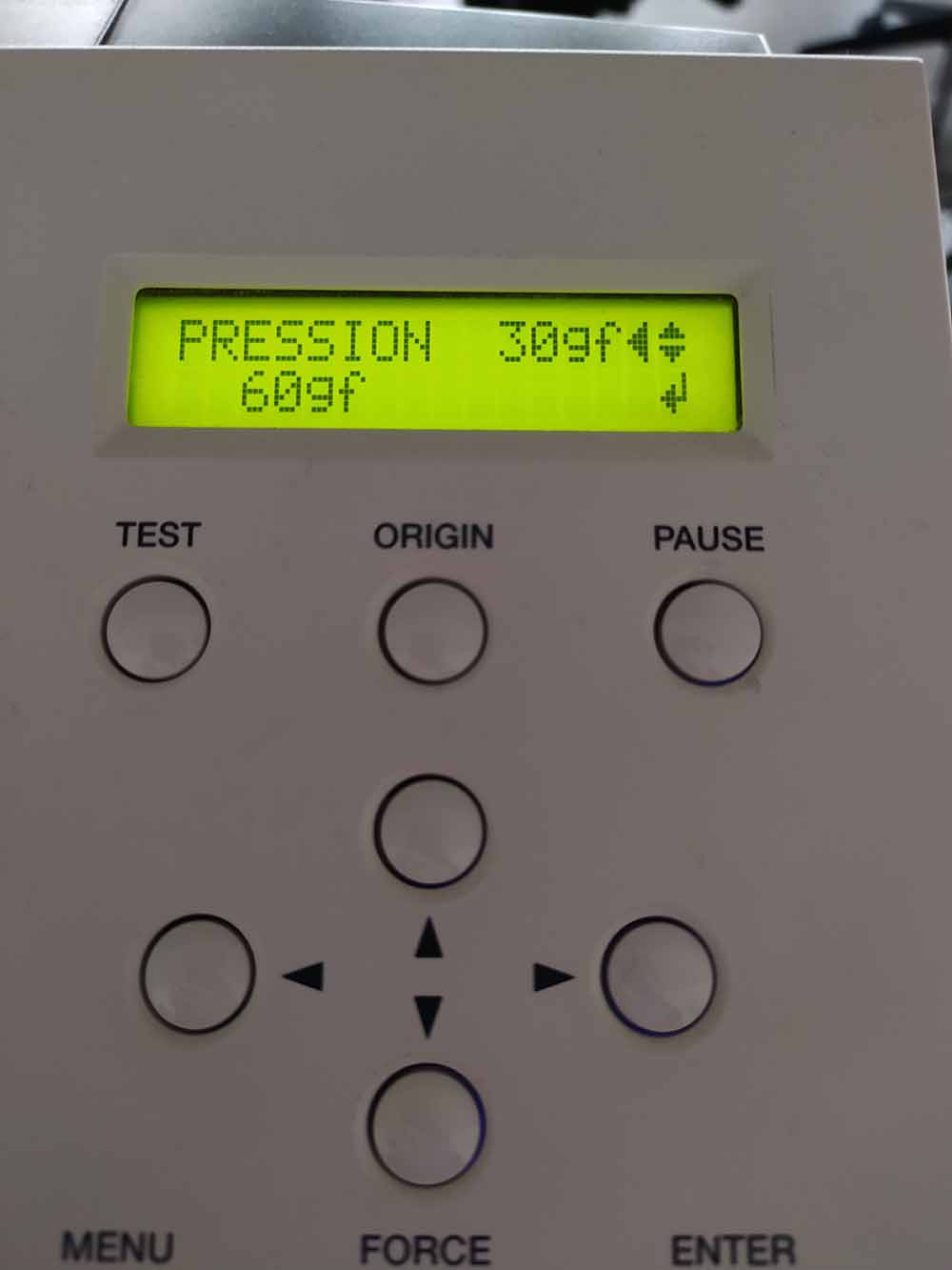
Here I set the force in several values cutting each time. It needed force value 60 with slider set to +1 to cut super clean for.
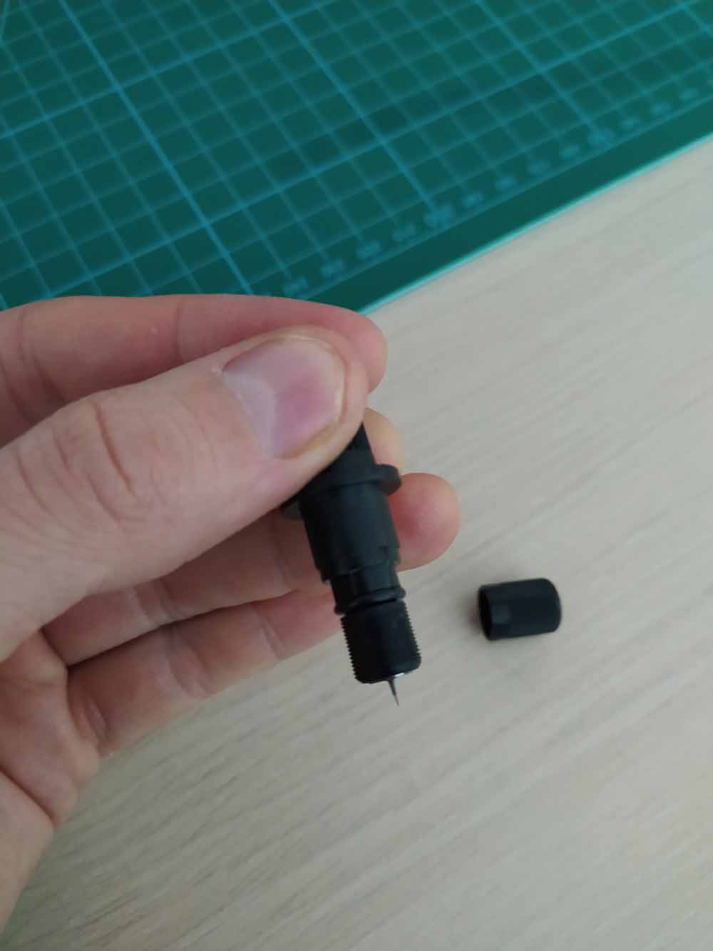
I had a look at the blade and took apart the assembly to see how it was installed.
Weeding was painful but I like the result !
Ladies and gentlement the oceanique video synth mock up: