8. Embedded programming
Here is the assignment for this week :
individual assignment: read a microcontroller data sheet program your board to do something, with as many different programming languages and programming environments as possible
group assignment: compare the performance and development workflows for other architectures
Individual Assignment: Program my board to do something
Here is my mini drone programmed a couple of weeks ago :
Individual Assignment: AVR Microchip Architecture + Atmel Studio Debug Mode
Here is a microcontroller primer based on the Attiny85 I made for this week’s content after reading the datasheet:
I really like Atmel Studio for the Debug mode where we can inspect the values of registers in real time. Here is me with a button sensing code examining the PINB register while I test the button. When the register value changes it goes red :

To get into Debug mode in Atmel Studio, change from Atmel ICE as ISP to Debug Wire under the Tool section:

Then click Control + S to save these parameters. Then hit Start Debugging and Break (Alt + F5).
Next you should see a window pop up telling you that you need to set the DWEN fuse (DebugWIRE Enable) to enable debugging mode. (To quickly check out fuses I go here: https://www.engbedded.com/fusecalc/).

Click ‘Yes’ and you should enter Debug mode. If you get this dialog box check your connections:

Just to show off how cool the Debug Mode in Atmel Studio is I programmed the EEPROM on the attiny84. EEPROM is tiny but useful for recording a parameter you want to remember in case the microchip loses power:
#include <avr/io.h>
#include <avr/eeprom.h>

int main(void)
{
    while (1)
    { uint8_t hello[] = "Wow this is really cool!";
    eeprom_write_block (hello, (void*)0x00AA, sizeof (hello)); // structure: void eeprom_write_block (const void *__src, void *__dst, size_t __n)
    }
}
And here’s what it produces :


Adding Breakpoints is easy, click beside the line you want to add a breakpoint to and a red dot will appear. You can use the symbols above to step around this line of code:

Individual Assignment: Arduino
Here is my Arduino workshop which I give to students this week :
Here is a series of basic coding classes I developed to help students with this week’s content (variables, arrays, control structure, etc. in Arduino):
…the second in the series, this focuses on Classes, nested loops, and 3D arrays :
Basic blink and button reading code can be found in the examples folder of Arduino.
Programming C and Assembly in Arduino is easy enough. You can code directly in the Arduino IDE in C as Arduino is written in C. For Assembly, if you click Control + Shift + N you’ll create a new tab in your sketch. Name this tab the same as the sketch but with a <.s> at the end. For example, if your sketch is called Blink.ino, you would create a tab called Blink.s. You should be able to paste assembly code directly in this tab and flash it to the Arduino. If you want to use single assembly commands in line, you can use the asm() command and put the assembly code you want to execute inside the brackets.

My technique for using Arduino IDE to program a custom board is to generate .hex from an Arduino sketch by going to Sketch>Export Compiled Binary and then Sketch>Show Sketch Folder to pick it up. I then flash the code using Atmel Studio as described in previous weeks. This allows me to benefit from the Arduino community in the form of libraries and fora, but to use the reliable method of flashing code that I have found with Atmel Studio + Atmel ICE Programmer in Windows / AVR Dude + our DIY USB Tiny Programmer on the command line in Linux.

It is possible to use the Arduino IDE to program attiny boards directly using Arduino as a programmer or using our TinyUSB programmers but I find going through Arduino, downloading cores etc., and using Arduino as a programmer seems less pro and more subject to error because of the number of hacks / bodges holding the whole thing together. Atmel Studio can even take Arduino libraries and sketches and program them if I ever needed a library for an Attiny that was only written in C++ of Arduino.

When coding in Arduino in C I use this handy conversion chart (not made by me! I got it from https://www.circuito.io/blog/arduino-uno-pinout/) to know what Port “Pin 13” is :
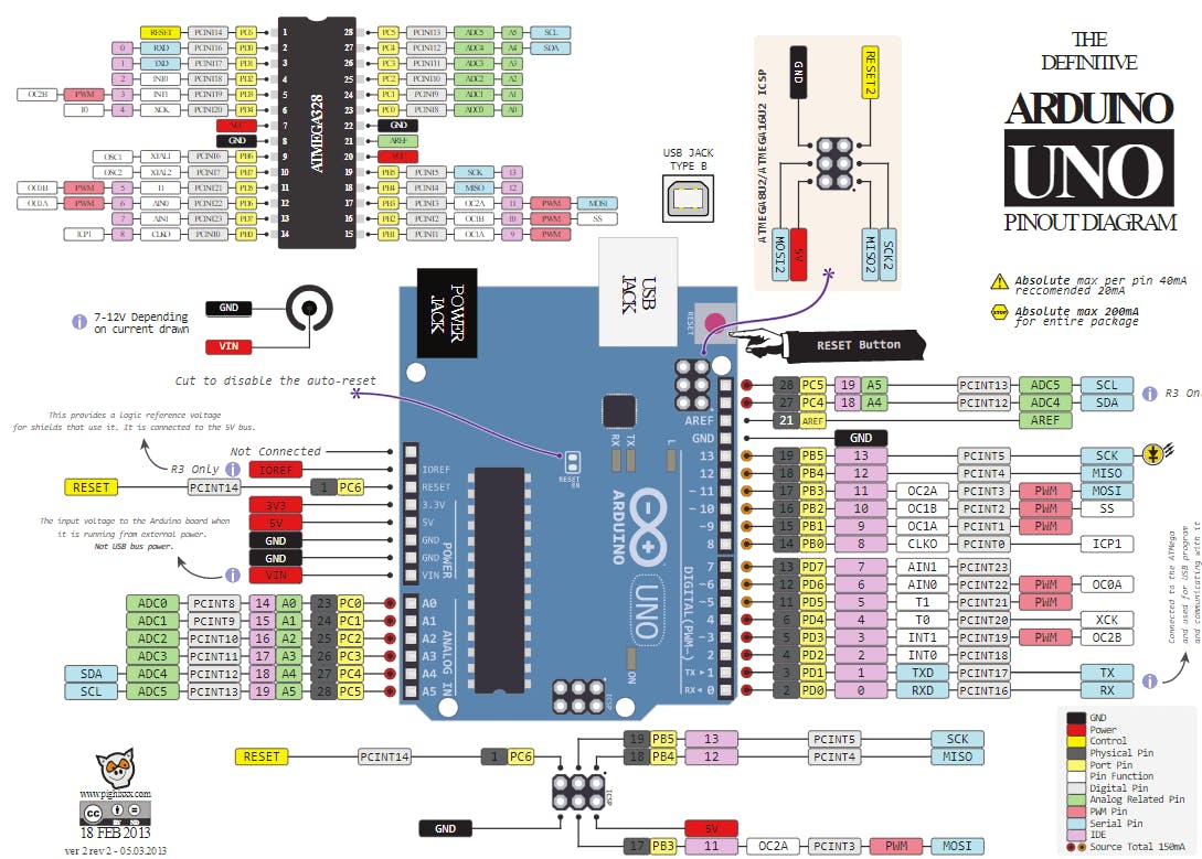
For example if I want to turn on the internal LED on pin 13 of the Arduin, I look for the yellow color tab across and see it is PORTB 5. This is equivalent to PORTB = 0b00100000 .
Individual Assignment: C
I am writing and flashing this code in Atmel Studio but it can also be done in Notepad and then compiled with a Makefile and then flashed using AVR Dude on the command line in Linux as I have shown in Week 04.
And here are some slides on a C workshop I am still working on:


I really like the MAKE book AVR Programming in C: https://www.oreilly.com/library/view/make-avr-programming/9781449356484/
Here is some code I developed for basic blinking:
 #define F_CPU 8000000UL // I also disable the CLKDIV8 fuse //

 #include <avr/io.h>

 #include <util/delay.h> // because I'm using _delay_ms() //

 int main(void)
 {
 DDRC = 0b00110001; //

 while (1) // while value inside the brackets is non-zero,
 {
 PORTC = 0b00100000; // All port A pins HIGH
 _delay_ms(1000); //1000ms = 1 second

 PORTC = 0b00010001; // All port A pins LOW
 _delay_ms(1000);

 }
 return (0);
 }
This code is for button reading, I modified it along with Quentin Benethuillere (http://fabacademy.org/2021/labs/digiscope/students/quentin-benethuillere/assignments/week06/) in our lab:
#define F_CPU 8000000

#include <avr/io.h>

#include <util/delay.h>


int main(void)
{
    DDRB = 0b11101111; //set PortB to all outputs except PB4

    while(1)
    {

        if ((PINB & (1<<4)) == 0) //if PB4 is 1, enter if
        {
            PORTB = (PORTB | (1<<3)) ; // turn on PB3
            _delay_ms(1000);
        }
        else
        {
            PORTB = (PORTB & 0b11110111); // turn off PB3
            _delay_ms(1000);
        }
    }
}
I also tried to create an interrupt but failed and I am not sure why yet…
The INT0 pin on the Attiny84 is PB2 and I have LEDS on PA1 and PA2.
/*
 * Attiny84 interrupt.c
 *
 * Created: 2/1/2019 12:58:37 PM
 * Author : FablabDigiscope
 */

#include <avr/interrupt.h>
#include <util/delay.h>

ISR(INT0_vect)
{
    if (PINB & (0b00000100)) // if this works out as non-zero it will execute...
    {
    PORTA |= 0b00000010; // set interrupt LED on
    PORTA &= ~0b00000100; // clear blinking LED bit
    }
    else
    {
    PORTA &= ~(0b00000010); // clear interrupt LED bit
    }
}


int main (void)
{
 PINB = 0b00000100; // pull up resistor for PB2
 DDRA = 0b00000110; // two LEDS output

 GIMSK |= (1 << INT0); // enable the INT0 external interrupt on pin PB2
 sei(); //enable global interrupts

 while (1)
 {

     PORTA ^= 0b00000100; //toggle the blinking light
     PORTA &= ~0b00000010; // turn off the interrupt light
     _delay_ms(200);

 }
}
Back in Week 06 I also made an analogRead and Debounce code in C.
Individual Assignment: Assembly
First off: why assembly? My personal answer is for pedagogical reasons, you learn about where memory actually goes when you program in assembly. It can also be useful for keeping your program size down and for doing something super fast.
I am writing and flashing this code in Atmel Studio but it can also be done in Notepad and then compiled with another assembly compiler and then flashed using AVR Dude.
An Assembly workshop I made for this week’s content (it gets into more detail about the x86 microchip but along with the attiny primer at the top of the page it give a decent overview):
I really like this set of assembly tutorials as well : http://www.rjhcoding.com/avr-asm-tutorials.php
I recommend Logisim to anyone curious about building 8 bit computers from the ground up: http://www.cburch.com/logisim/
This simple code just turns on the built in LED on the Arduino.
Certain registers on the AVR are general purpose like r16 and r17, others are not as accessible.
;
; AssemblerApplication1.asm
; Turns on the pin 13 LED on the arduino
; Created: 3/17/2021 09:40:24
; Author : FablabDigiscope
;


    .cseg // stands for code segment
    .org    0x00 // not 100% necessary but this specifies the location where the code will be stored

        ldi    r16,(1<<5)       ; load 00100000 into register 16 (alternatively: r16, 0b00100000)
        out    DDRB,r16         ; write register 16 to DDRB
        out    PORTB,r16        ; write register 16 to PORTB (i.e. turn on the LED)

loop:   rjmp    loop            ; stay in infinite loop
This code technically blinks the same LED. Blinking once a second in assembly is not trivial and involves counting the number of clock cycles various operations require (and this varies sometimes depending on the outcome of the operation). I was able to confirm this worked by checking with the oscilloscope however.
        .cseg
        .org    0x00

start:      ldi r16,0b0010000       ; load 00100000 into r16
            clr r17                 ; load 00000000 into r17
            out DDRB,r16            ; set PINB5 to output
            out PORTB,r16           ; set PINB5 to HIGH

            ldi r24, 100            ; load 1000 into r24, our counter register

loop1:      sbiw    r24,1           ; decrement r24 by 1 (100-1 the first time)
            brne    loop1           ; branch to the label loop1 if not zero

            out PORTB,r17           ; set PINB5 to LOW

            ldi r24, 100            ; load 1000 into r24 again

loop2:      sbiw    r24,1           ; decrement r24 by 1
            brne    loop2           ; branch to loop2 if not zero

            rjmp    start           ; jump back to start
I have two loops here, one for the LED being on and another for it being off. A more sophisticated version of this code would have involved toggling the state of the LED in a loop but I wanted to keep this extremely simple to understand.
This code reads a button state and turns on the LED:
    .cseg
    .org    0x00

//plug in button to D5, and LED to B5

start:  ldi r16, 0b00100000 ; load 00100000 into r16
        out DDRB,r16        ; set PINB5 to output
                            ; PORTD is set to input by default


main:
     in    r17,PIND         ; Button state goes into r16

     out   PORTB,r17        ; Write contents of r16 to PORTB

     rjmp    main           ; loops back to the start of Main