Final Project
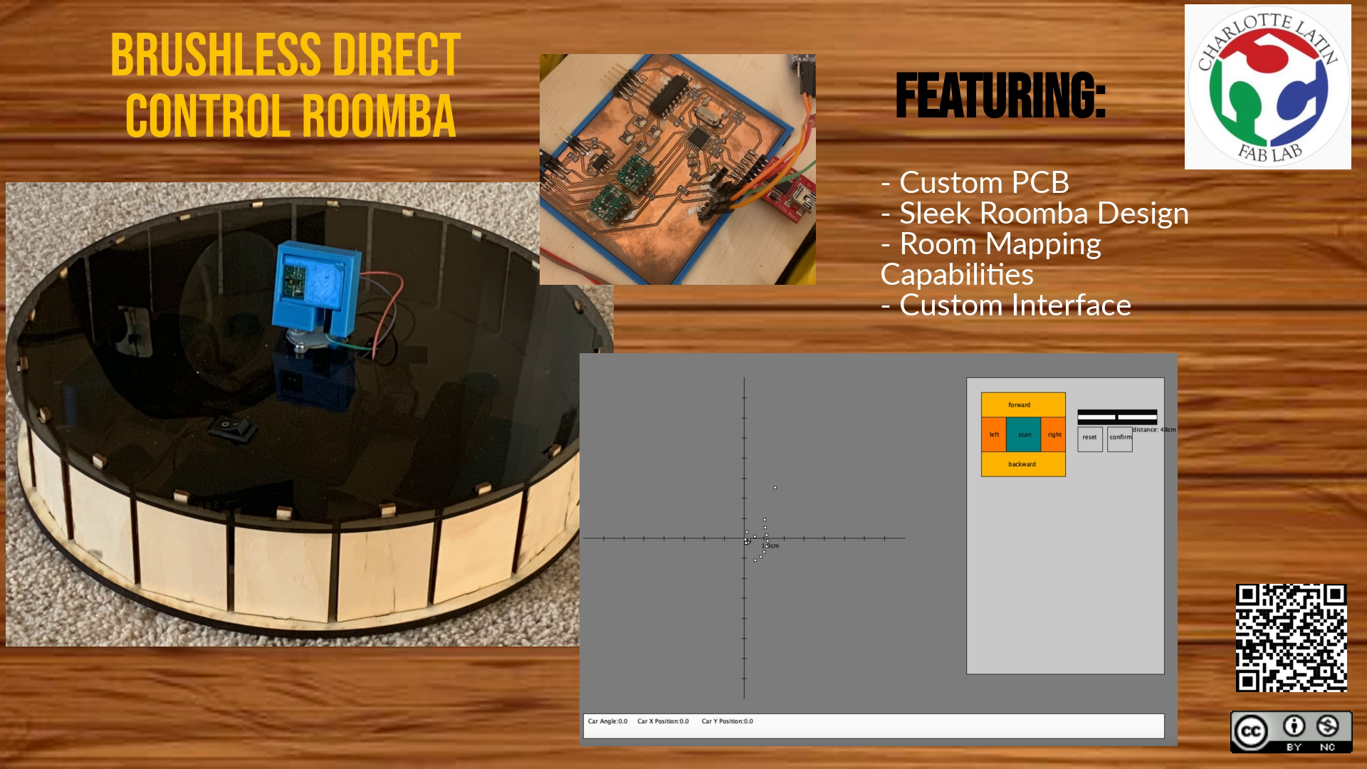
My idea for my final project is an autonomous car that could map out a room with a distance sensor and upload the image of the room to a web server.
During week one, I worked on choosing an idea for my final project and developing it.
Project Management
My final project will be creating a robot car that can map out a room and upload the map to a website. I will map out the room by tracking the position of the car and by using a distance sensor. To track the position of the car, I will use math to determine the position and angle from the motor movements instead of using a gyroscope.
This is a general idea of how my code would work. I will use a stepper motor along with my distance sensor because it would allow me to take data without moving the actual car, which would improve the accuracy of the points (in case of slippage), and it would decrease the total power used.
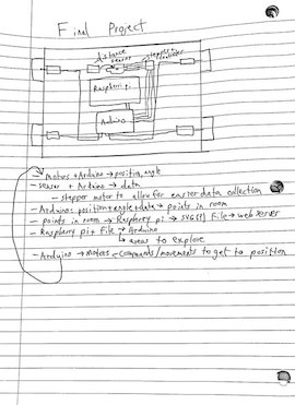
For the main body of the car, I will use the CNC machine to cut out a frame with slots for electronics and motors. I will 3D print brackets and casings for motors. I will also 3D print the wheels and create grips for the wheels and padding on the car by molding and casting. For input devices, I will use some form of a time of flight (distance) sensor. One promising sensor was the VL53LOX because it was small, cheap, and had enough range and accuracy for my project. Along with the sensor, I will probably have a stepper motor that will spin the sensor to make it easier to take measurements without moving the car. I will also have four motors to spin the wheels on the car. I will use a sashakit board to control the motors and sensors, and the board will also process the data. I will then send this data to a raspberry pi, and upload it to a web server. I will create an interface to display this data, and maybe allow for remote control of the car.
List of Parts
| Machine | Part |
|---|---|
| CAD | Design the main body of the car |
| computer-controlled cutting | Body and framework for electronics |
| electronics production | Sashakit microcontroller, motor boards, ToF sensor |
| 3D scanning and printing | 3D print the wheels and casings for motors |
| embedded programming | Code to make the car autonomous, code for sensors and motors |
| input devices | ToF sensor |
| output devices | Motors |
| molding and casting | Grip for wheels, pads for car |
| networking and communications | Raspberry Pi to send data of a room to a server |
| interface and application programming | Interface to show the data and maybe control the car remotely |
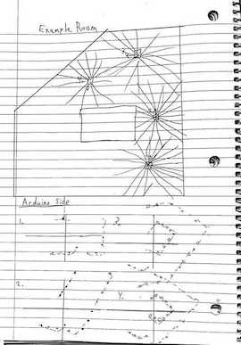
The car will start at some position in a room, and it will drive around, take data, and map out the room. I will do this by having it drive to specified points, and then have the distance sensor and stepper motor take data from a circle.
The car will start initialized at 0,0 0º and will drive around and map out a room relative to this starting position
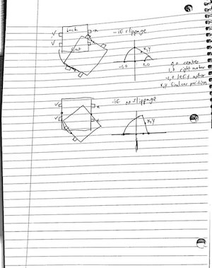
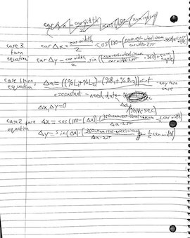
Before I started developing my idea, I wanted to make sure I could accurately track the position of the car. I wrote a few equations for different ways the motor could turn- cases 1, 2, and 3 in the images. Case 1 is the right motor is moving the opposite amount of the left, case 2 is the left motor is moving and overpowering the right, but the right motor is on or slipping. Case 3 is the left motor is on, and the right motor is off and not slipping.
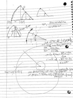
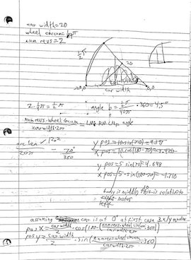
Final position tracking equations
∆A=((%L1+%L2)-(%R1+%R2))*t*c
%L/%R=how much the left or right motors are on
c=constant, 1º/(%*sec)- I need data to find this
t=time
ai=initial angle of the car
∆a=change of the angle of the car
∆X/∆Y=change in the position of the car

Case 1 (Left on, right equally on but opposite direction):
∆X=0
∆Y=0

Case 2(Left on, right on but slower or slippage):
∆X=(cos(180-∆a-ai)+cos(ai)))*(360*num RevolutionsL*wheel Circumference/(∆a*2π)-½*Car Width)
∆Y=(sin(∆a+ai))+sin(-ai)))*(360*num RevolutionsL*wheel Circumference/(∆a*2π)-½*Car Width)

Case 3(Left on, Right off, no slippage):
∆X= Car Width/2*(cos(180-(360*num RevolutionsL*wheel Circumference/(car Width*2π))+ai))+cos(180-ai)))
∆Y= Car Width/2*(sin((360*num RevolutionsL*wheel Circumference/(car Width*2π))+ai)+sin(-ai)))
Week 06, Electronics Design
Since I finished all the work for electronics design week on the first day, I decided to start thinking about and designing my board for my final project. I wasn’t entirely sure about what type of distance sensor I wanted to use, but I knew that I wanted to use 4 DC motors to drive my car and a stepper motor to adjust the angle of the distance sensor. I started by looking into the types of DC motors and what was required to control one. I decided to use four DC motors to drive my car since they are small, simple to control, and have fairly high RPM. I will also use a stepper motor similar to the 28byj-48 stepper motor.
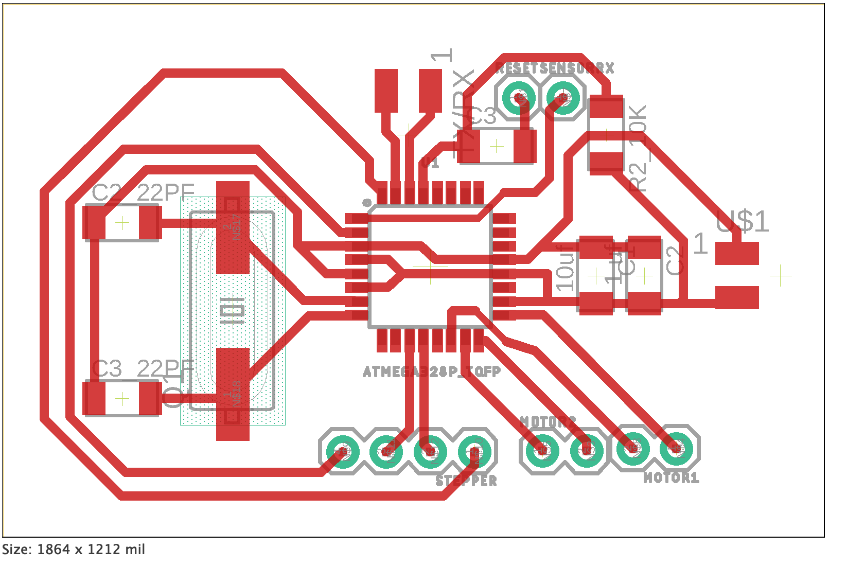
I started by designing a board similar to Sashakit. I did not include a couple of the LEDs, but the other components and layouts are the same. Right now, I have all the header pins that were in the original Sashakit, but when I finalize my output and input boards, I will remove all the unnecessary header pins.
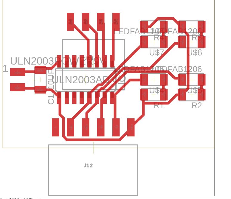
After designing my Sashakit board, I designed two motor boards for the stepper motor and 4 DC motors. For the stepper motors, I used the ULN2003A chip. This chip is in the driver board for the stepper motors in our lab, and it is very simple to use. I will use 4 of its 7 inputs, and the chip has 4 output lines as well as a common ground line that will connect to the stepper motor. All I had to do was connect the input lines to 4 port pins on my 328 chip, it doesn’t even need PWM.
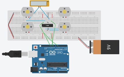
The next motor board I made was the one to control my DC motors. I decided to use the L293D chip after looking through a few options for H-Bridge Chips. An H Bridge chip allows me to both 1. control the rpm of a dc motor through PWM, and 2. separate the high voltage and current required for the motors from the microcontroller board. I control the board through 4 input lines that require PWM, and I output the voltage through four output pins. The input voltage needs to be higher than 1/2 the reference voltage (Vss) to produce a logical 1, so I will connect the Vss pin to 9V and the input pins to 5V from the 328 pins. Each pair of output pins connects to one DC motor, so I will be connecting the motors on each side of my car in parallel. I simulated the operation of this board through Tinker Circuits, the circuit diagram looks like this:
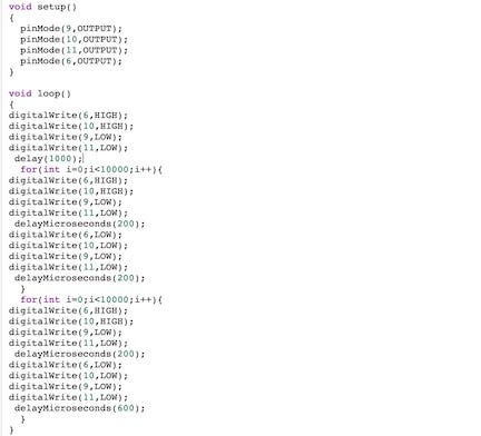
I wrote a few lines of code to help me understand the PWM functions through this board. From what I understand, a constant logical 1 (5V) will result in the DC motor constantly being on, which will max out its RPM. If PWM is used, the RPM of the DC motor will be adjusted according to the ratio of high time to low time. For example, a 1:1 ratio will result in about 1/2 the RPM, while a 1:3 ratio will result in about 1/4 the RPM. I can use PWM to control the speed of each pair of motors on my final car.
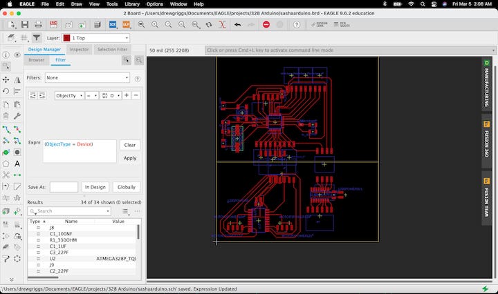
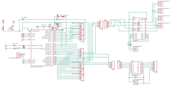
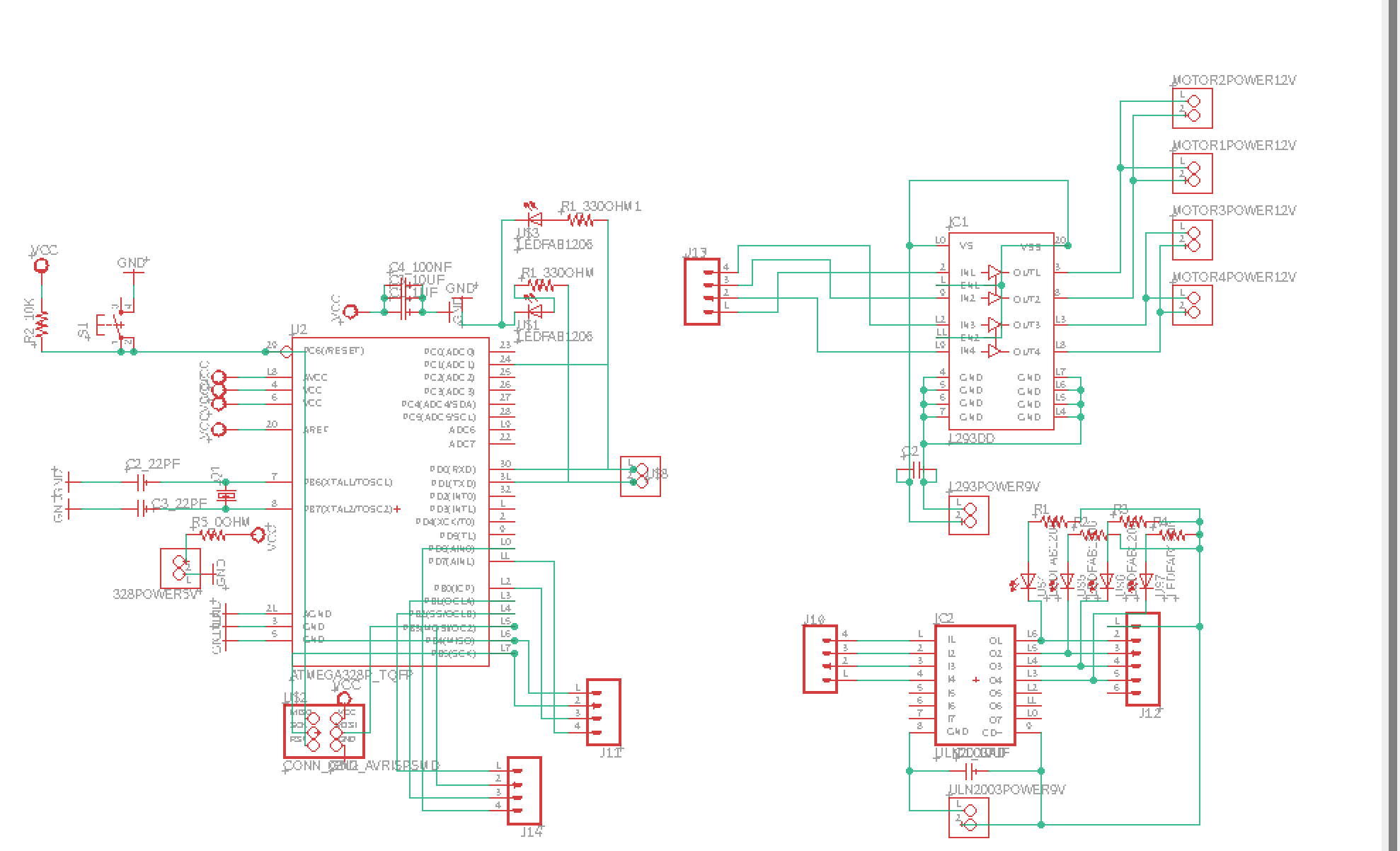
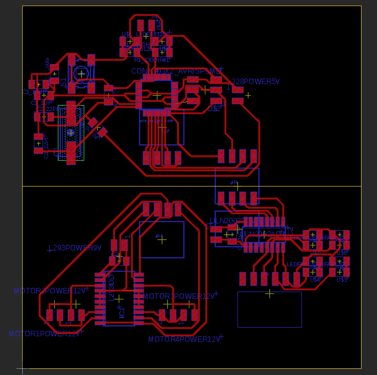
After understanding the pin layout and functions of the two chips, I added each chip into the Sashakit eagle cad file. I added a few components- mostly headers and a few capacitors. I then looked through the pinout of my sashakit and decided to use the PWM pins PD6 and PB1-3 for my L293D board. I decided to use the pins PB4-5, PB0, and PD7 for the stepper motor. The schematic and board diagram up to this point looks like this:
After creating these two boards and creating header pin connections, I decided to add a TX and RD LED to help with debugging, a solder jumper so that I can disable the test LEDs, and I removed a random 0 OHM resistor that I had added earlier when trying to fix my routes. Currently, my board looks like this:
When I finalize my board, I will remove all the unnecessary pin headers. I will also add a voltage regulator to draw the 9V battery down to 5v for the microcontroller board and possibly lower for a sensor board. I will use a 9V battery because I need 9V for most DC motors.
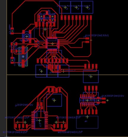
After reading into the datasheet for the ULN2003a board out of curiosity, I learned I would need some LEDs to prevent some complications with the chip. I also adjusted a few other things in my main schematic, primarily leds and data tx/rx pins, removing headers that wouldn’t be used, adding programming pins, and some other changes. My current board and schematic looks like this:
Week 08, Embedded Programming
This week, along with the weeks assignments, I started writing pseudocode (or something like that) to lay out what my code would have to do. So far, it just has what I want it to do- I haven’t started writing actual pseudo code except for the move foreward and backwards functions.
float array
     {pos x}
     {pos y}
float carposx
float carposy

void setup() {
setup motor dc pins
  dcpins[left+, left-, right+, right-]
setup stepper pins
  stepperpins[1, 2, 3, 4]
setup sensor pins
setup tx rx
establish serial connection with pi
}

void loop() {
recieve type of instruction
  gcode type instruction? simplify
  explore, explore in region, wait, etc
move based on instruction
  autonomous
  surrounding area
  area at point
    movement instructions
  movement instructions
  wait
take input and move based on instruction
upload to pi
wait for pi instruction
}

recieve type of instruction
{
 serial communication with pi
 recieve number or gcode type instruction
 return type of movement to make
}

move based on instruction
{
 if 1, autonomous
 if 2, explore surrounding area
 if 3, movement instructions then surrounding area
 if 4, movement instructions
 if 5, wait
}

take input and move based on instructions

1. autonomous (give duration to run for, return a large amount of data points and car final position and angle)
{
determine car position or initialize as 0 0 0º
spin sensor and take input
use math to determine data positions
check four quadrants, if a quadrant has no data, move there
determine car position
repeat until timer runs out
}

2. explore surrounding area
{
initialize car position or find car position
spin stepper and take measurements
return data positions
}

area at point
{
 calculate deltas
 determine required change in angle
 change angle and calculate change in position
 move and calculate movement
 spin stepper and take measurements
 return data positions
}

movement instructions
{
 calculate deltas
 determine requried change in angle
 change angle and calculate change in position
 move and calculate movement
 return position
}

wait
{
 wait
}

upload to pi
{
  upload data- massive 2d array?
  upload car position and angle
}

wait for pi instruction
{
  just do that
}

void moveStraight(dir(1=foreward, 0=backward), dur, uint8_t spd)
{
if(dir)
  {
  analogWrite(left+,spd)
  analogWrite(right+,spd)
  digitalWrite(left-,LOW);
  digitalWrite(right-,LOW);
  delay(dur)
  }
else
  {
  analogWrite(left-,spd)
  analogWrite(right-,spd)
  digitalWrite(left+,LOW);
  digitalWrite(right+,LOW);
  delay(dur)
  }
for(int i=0;i<4;i++)
{
  digitalWrite(dcpins[i],LOW);
}
}

void moveAngle(angle, uint8_t spd)
{

}
Week 10, Input Devices
This week, I designed and tested a LIDAR distance sensor breakout board from Pololu. The board is the VL53L1X distance sensor. I chose this sensor because it is small and discrete, yet still has a 4 meter max range under optimal conditions.
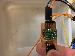
I developed a board with the ATtiny1614 chip because it had I2C communication capabilities, which was required for my distance sensor. I connected my chips I2C pins to the I2C pins on the distance sensor, and added control shutdown pins (which I ended up not using). I also added an LED for testing purposes, and tx/rx pins for serial communication.
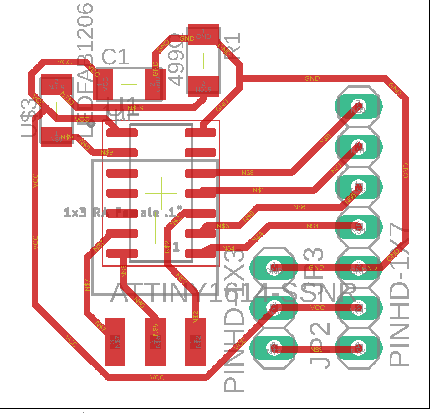
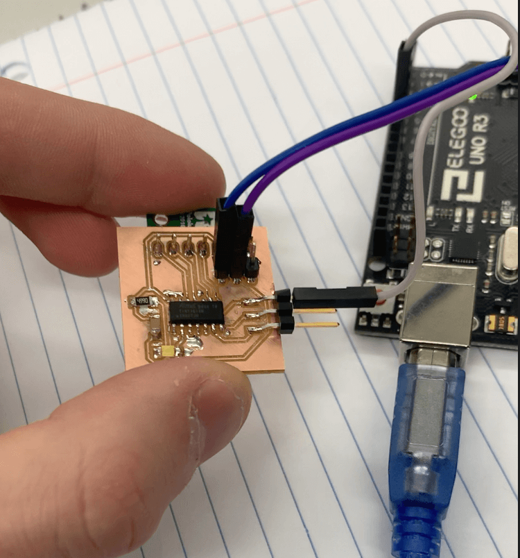
I milled and tested this board, and got impressive results in terms of accuracy and range:
The accurate results means that I will have a simpler time coding the logic to control my robot. With innacurate results from taking horizontal data, I would have to either take a few averages or only accept data if it is in a range near my car. Each of these solutions would increase the complexity and processing time required for my car, so it is useful to not have to deal with it.
Week 12, Output Devices
This week, I started designing and testing boards that would control the outputs for my final project. My final project will include 4 brushed dc motors for movement and a stepper motor to adjust the angle of my sensor.
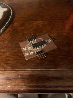
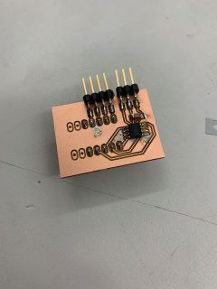
To control the stepper motor, I will use the ULN2003A chip, which is used in a breakout board developed by ELAGOO. I tested it with an Arduino UNO because my final project will use an ATMega328p chip, which is the same one in the UNO.
I had to include 4 LEDs to prevent damage to the chip from the motor, as well as pin headers for the stepper and input/power leads, and a capacitor to regulate current.
I also designed a board to test the DRV8838 h-bridge chip breakout board from Pololu. I will have 2 of these board to control 2 motors each in parallel. I designed a test board with the ATTiny412 chip to test it, and after some problems with PWM pins, I was able to control the motors.
The stepper motor will be used to spin the sensor so I can take data from any angle. The 5V stepper motor I selected is geared- the datasheet said it had a ratio of about 1:64 (some forum members claimed it was slightly less, like 63.68, but I will use the datasheets 1/64 value) so I will have no problem calculating change in angle just from steps. The DC motors I chose are 6V and geared, so I will not have major issues involving tourque. I will also have enough current to run them- I am using a 5V voltage regulator to step the voltage from 6V for my main boards and stepper motor, but the DC motors will not cut into this supply. For power, I will likely use either a Lithium Ion 6V battery or 4 AA batteries. I may add a separate voltage regulator just for the stepper motor so I dont draw too much current from it.
Week 13, Networking and Communications
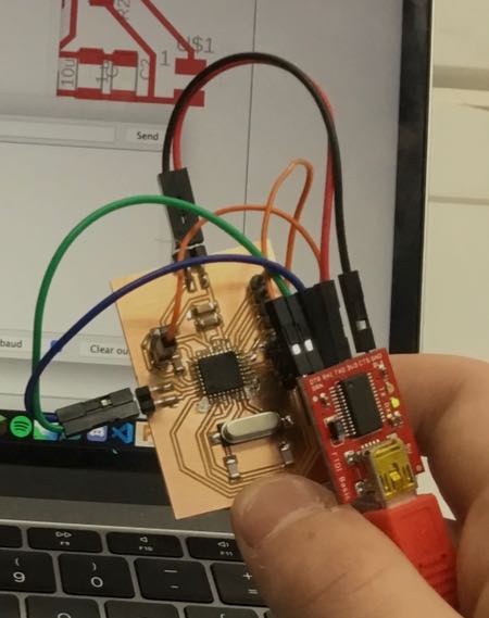
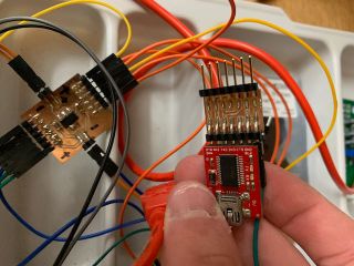
During this week, I created a master board to communicate with all my other boards, a power regulator board, a FTDI adaptor board to program my board, a breakout board for my DRV8838 chip, as well as adding a separate TX/RX pin in parallel for my HC-05 bluetooth chip. I started with the main master board.
The master board included 2 pins for each one of my DC motor regulators, 4 data pins for controlling my stepper motor, a data pin for recieving serial data from my sensor board, pin headers for TX/RX for programming and sending data by bluetooth, a reset pin for programming, and power and ground pins. It also included a clock module. Since my final project electronics will be isolated inside the case of my car, I will not worry too much over cable management. I will organize my electronics in the most effective ways and just connect everything by jumper cables.
I milled out and soldered my board, and made a few revisions. I mostly just increased some trace thicknesses, but I also put my recieving pin from my sensor board next to my reset pin just to add a bit of structure to them since I quickly ripped them on my first board. I still found that they were somewhat loose while removing jumper cables, so I applied some superglue to strengthen them. While programming, my classmate Teddy Warner was having issues with his ATMega328 chip. I went into greater detail about the process in determining the problem in my documenation for networking week, but a bin of speakers directly underneath the 328 chips had ruined most of the chips. We bootloaded the remaining ones with a Sashakit to try to find working ones. This allowed me to not need ISP programming to bootload the chip, so I could just upload programs through the FTDI chip, which just needed a reset and tx rx lines.
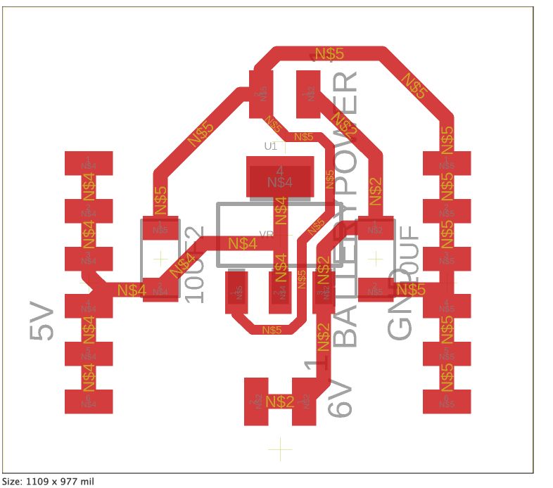
Next, I created a power regulator board. I counted the total number of power and ground pins I would need, and I came up with a schematic using a 12V-5V voltage regulator. The regulator is constant, so any voltage level between 5.5 and 12 will drop to 5. My power schematic included a row of 5V/ground pins, 2 6V pins for motors, and a 6V/ground input power. I soldered the board and tested it, and found that it did drop the power.
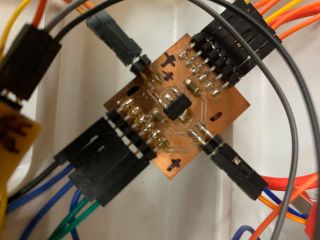
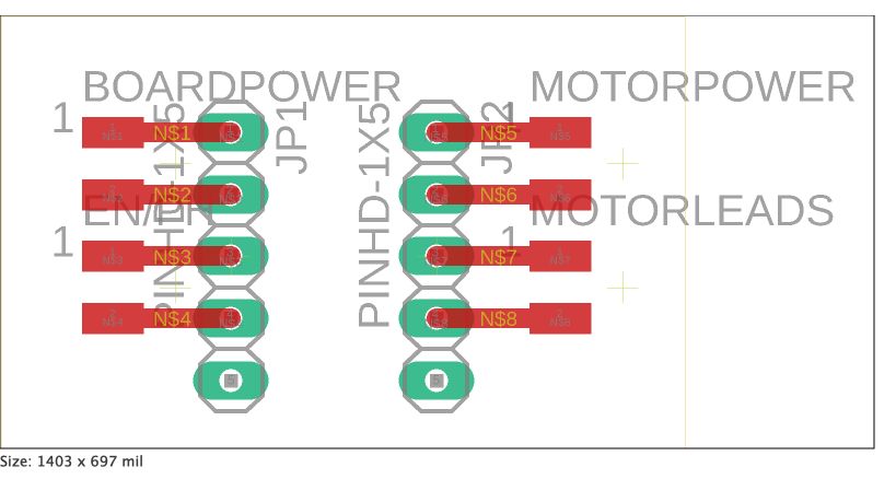
I then created a breakout board for my DRV8838 chip. This would just have jumpers that connect to the chip, since the drv chip is through hole, but my electronics will be surface mounted. I just used 4 pins per side, since 2 of the 10 pins on the board are not needed. After some problems with the distance between holes on the through hole pin headers, I was able to allign and solder the drv chip.
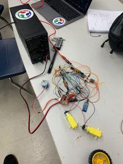
Before moving on to the FTDI adaptor board, I put together all my electronics and tested them. At this point, I had 7 boards- 1 master board, 1 sensor board, 2 drv breakout boards, 1 power regulator board, 1 stepper motor board, and 1 bluetooth module. The seven boards had a large number of jumper cables connecting them, so cable management looked like a mess in the video. For my final project, my boards will be taped down and orgainized in the most efficient way, so it should seem slightly better. I wrote some code to run each component, attached my power board to a power supply set to 6V, and ran everything. I found it was successful, and each component was working.
After testing, I designed the FTDI chip breakout board. I also included a updi pin in case I wanted to reprogram my sensor board. In total, I included 2 different tx rx pins in parallel on one side, a reset line, common ground, and updi lines on one side, and an FTDI header and updi pin on the other. I soldered the board, and added it to the pile, currently numbering 8 boards.
Final Project Development Weeks
Final Board
The boards I designed up to this point were all functional, but they required a lot of jumper cables to connect everything. This created some problems for cable management, and I would have to fix this before moving on to final project CAD.

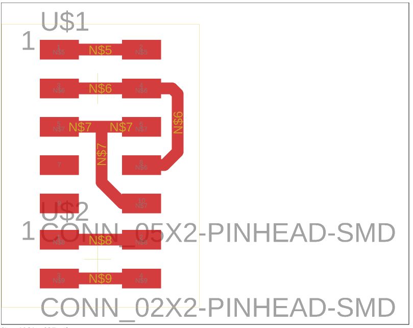
To fix this problem, I turned to eagle. I started by copying and pasting all my boards up to this point into a schematic file, then worked to connect everything via nets. I then created a board file from the schematic, and after about 3-4 hours of adjustments, I had a completed board design.
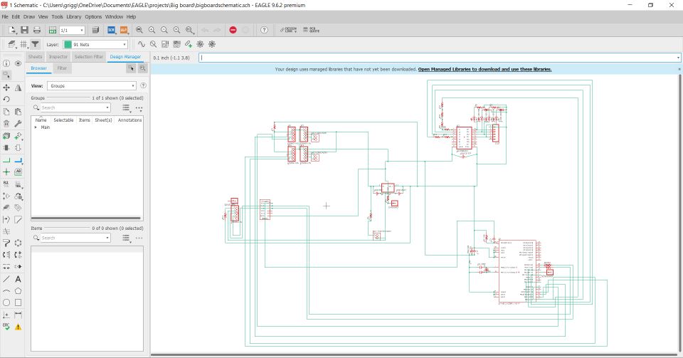
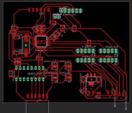
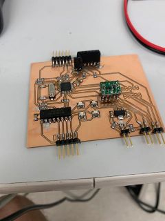
I then milled and soldered my board. My board is considerably larger than all the ones I’ve created up to this point, and it includes the funcitonality for all of the previous ones. It took up most of the bed while machining, and it took me over an hour to solder. After about 5 hours of working on my board, I finished and tested it. I was able to upload code to it, and the stepper motor and dc motor portions were working corretly. I still have to test the second dc motor driver since I had to order some extra driver chips, but so far it seems perfectly functional.
CAD
With a board designed for better cable management completed, I started on the cad. I designed a car based on a Roomba because Roombas also map the rooms they clean in order to clean more efficiently. I then designed cases for the various components in my project- such as motors, batteries, electronics boards, etc. Finally, I designed the top and the case that would allow my sensor to spin with a stepper motor.
I then 3D printed the parts. It took a few iterations to get the dimensions right, and after some trial and error, all the pieces were working.
Software
Interface- Processing 3
After finishing the physical elements, I started working on the software side of my project. I started by finishing my interface I developed in interface and applications programming week. I had the artistic side complete, but the networking aspect was not finished. A larger explaination of the functions and my code can be found under my Interface and Applications Programming week.
import processing.serial.*;

Serial port;


int mainwid = 1300;
int mainheight = 800;

int displaywid = 650;
int displayheight = 650;
int midpointx = displaywid/2+50;
int midpointy = displayheight/2+50;

int controlwid = 400;
int controlheight = 600;

int datawid = 1175;
int datalen = 50;

int[][] pointdata = new int [400][2];
float[][] mappeddata = new float [400][2];
int yoffset = 50 + displayheight / 2;
int xoffset = 50 + displaywid / 2;
float scale = 10;

float carangle = 0;
float carx = 0;
float cary = 0;


int tSx0;
int[] outdata = new int[5];

boolean indir = false;
boolean indir2 = false;

int x;
int angle;
int distance;
int type; //1/2 F/B, 3/4 L/R

void setup()
{
 size (1300,800);   //size
 port = new Serial(this, Serial.list()[1], 9600);
 port.bufferUntil('\n');
 drawSetup();
}

void drawSetup()
{
 fill (125);
 rect (0,0,mainwid,mainheight);   //main area rectangle

 fill (0);
 line (50,50+displayheight/2,displaywid+50,displayheight/2+50); //x axis
 line (50+displaywid/2,50,displaywid/2+50,displayheight+50);    //y axis
 for(int i = 1; i < 8; i++)
 {
   line((midpointx+i*displaywid/2/8),midpointy-5,midpointx+i*displaywid/2/8,midpointy+5);
   line((midpointx-i*displaywid/2/8),midpointy-5,midpointx-i*displaywid/2/8,midpointy+5);
   line(midpointx-5,(midpointy+i*displaywid/2/8),midpointx+5,(midpointy+i*displaywid/2/8));
   line(midpointx-5,(midpointy-i*displaywid/2/8),midpointx+5,(midpointy-i*displaywid/2/8)); //grid
 }
 text((scale/10 + "cm"), midpointx+displaywid/16-5, midpointy+20); //text for scale
 fill (200);
 rect (displaywid+100+75,50,controlwid,controlheight); //controls interface
 fill(250);
 rect (50, mainheight-70,datawid,datalen); //data line
 fill(0);
 text("Car Angle:" + carangle,60, mainheight-50);
 text("Car X Position:" + carx,160, mainheight-50);
 text("Car Y Position:" + cary,290, mainheight-50);

 controlpannelsetup();
}

void controlpannelsetup()
{
 fill(0,128,128);
 rect(855,80,170,170);
 fill(255,180,0);
 rect(855,80,170,50);
 rect(855,200,170,50);
 fill(255,120,0);
 rect(855,130,50,70);
 rect(975,130,50,70);
 fill(0);
 text("forward",910,110);
 text("backward",910,230);
 text("left",872,170);
 text("right",990,170);
 text("scan",930,170);
}

void mousePressed()
{
 delay(100);
 if(mouseX > 855 && mouseY > 80 && mouseX < 855 + 170 && mouseY < 80 + 50){print("forward"); type = 1; move();}
 if(mouseX > 855 && mouseY > 200 && mouseX < 855 + 170 && mouseY < 200 + 50){print("backward"); type = 2; move();}
 if(mouseX > 855 && mouseY > 130 && mouseX < 855 + 50 && mouseY < 130 + 70){print("left"); type = 3; move();}
 if(mouseX > 975 && mouseY > 130 && mouseX < 975 + 50 && mouseY < 130 + 70){print("right"); type = 4;move();}
 if(mouseX > 855 + 50 && mouseY > 80 + 50 && mouseX < 975 && mouseY < 200){
  print("scan");
  String message = "";
  message = "<" + "9" + "," + "0" + "," +  ">";
    print(message);
  port.write(message);
  }        // print here will be replaced with btport print for final code
 if(indir && mouseX > 1050 && mouseX < 1050 + 160 && mouseY > 115 && mouseY < 115 + 30)
 {
   drawSetup();
   controlpannelsetup();
   move();
  fill(0);
  rect(mouseX, 125, 5, 10);
  if(type == 3 || type == 4){
  float fx = map(mouseX, 1050, 1050 + 160, 0, 180);
  x = round(fx);
  angle = x;
  print(angle);
  text("angle: " + x, 1161, 160);
  }
  else if(type == 1 || type == 2)
  {
    float fx = map(mouseX, 1050, 1050 + 160, 0, 100);
    x = round(fx);
    if(type == 2){text("distance: -" + x + "cm", 1161, 160);}
    else if(type == 1){text("distance: " + x + "cm", 1161, 160);}
    distance = x;
  }
  indir2 = true;
 }
 if(indir2 && mouseX > 1100 && mouseY > 150 && mouseX < 1100 + 50 && mouseY < 150 + 50)
 {
   indir = false;
   indir2 = false;
   print("confirm");
   String message = "";
   if(type == 3){
     message =  "<" + "3" + "," + angle + "," + ">";
     print(message);
   port.write(message);
   }
   else if(type == 4){
   message = "<" + "4" + "," + angle + "," + ">";
   port.write(message);
   print(message);
   }
   else if(type == 1){
   message = "<" + "1" + "," + distance + "," + ">";
   port.write(message);
   print(message);
   }
   else if(type == 2){
   message = "<" + "2" + "," + distance + "," + ">";
   port.write(message);
   print(message);
   }
//prints here will be replaced with btport prints to send the data for movements
  drawSetup();
 }
 if(indir && mouseX > 1050 && mouseY > 150 && mouseX < 1050 + 50 && mouseY < 150 + 50)
 {
   indir = false;
   indir2 = false;
   print("reset");
   drawSetup();
 }
}

void move()
 {
   indir = true;
   fill(10);
   rect(1050,115,160,30);
   fill(250);
   rect(1050,125,160,10);
   fill(200);
   rect(1110,150,50,50);
   fill(0);
   text("confirm",1115,175);
   fill(200);
   rect(1050,150,50,50);
   fill(0);
   text("reset",1060,175);
   delay(500);

}

void draw()
{
mapdata();
fill(255);
for(int i = 0; i < mappeddata.length; i++)
{
  if(mappeddata[i][0] == 0){break;}
  rect(mappeddata[i][0],mappeddata[i][1],5,5);
}
delay(1000);
}

void serialEvent(Serial port) {
   port.readStringUntil('<');
   String data = port.readString(); //catch serial data
   print(data);
  try {

    int[] input = int(data.trim().split(",")); //split input string by ,
        for(int i = 0; i < 5; i++){
     println(input[i]);
   }
    if(input[0] == 1)

    {
    for(int i = 1; i < input.length; i+=2){ //for each pos in input data
     for(int j = 0; j < pointdata.length; j++){
      if(pointdata[j][0] == 0){ //check if value at incrementing pointer is set, if set, do nothing and continue, if not set, add more data starting from here
      pointdata[j][0] = input[i];
      pointdata[j][1] = input[i+1];
      break;
      }
    }
   }

  }

  }
  catch(Exception e) { //java do java reeeeeeeeeeeeeeeeeeeeeeeeeeeeeeeeeeeeeeeeeeeeeeeeeeeeeeeeeeeeeeeeeeeeeeee
    e.printStackTrace();
  }
// mapdata();
 //drawpoints();
}

void mapdata()
{
  for(int i = 0; i < pointdata.length; i++)
  {
   float mappedpointx = pointdata[i][0]*1/scale;
   float mappedpointy = pointdata[i][1]*1/scale;
   mappeddata[i][0] = mappedpointx + xoffset;
   mappeddata[i][1] = mappedpointy + yoffset;
  }
/*  for(int i = 0; i < mappeddata.length; i++)
  {
   if((mappeddata[i][0] > displaywid + 50 || mappeddata[i][0] < 50) || (mappeddata[i][1] > displayheight + 50 || mappeddata[i][1] < 50))
  {
   scale *= 2;
  }
 }
 */
}
Embedded Programming- Arduino IDE
While working on my interface, I developed the code on the Arduino side as well. I was able to finish this part quicker than the processing side since I didn’t have to find coordinate in an interface for each section. The arduino code takes bluetooth serial input, breaks down the input string into usable data, and powers the motors and reads sensors based on the instructions.
The first part of my code includes the software serial library to network with my sensor board, the stepper library to easily control the stepper motor, and defines the pins and other information for the main board.
#include <SoftwareSerial.h>
#include <Stepper.h>

#define stepsperrevolution 2048
#define stepangle stepsperrevolution / 360*1/4

#define stepper1 2
#define stepper2 8
#define stepper3 7
#define stepper4 4

Stepper stepper(stepsperrevolution, stepper1, stepper3, stepper2, stepper4);

#define leften 11
#define leftph 12
#define righten 10
#define rightph 13

#define sensdx 3

#define sserial 5
#define sserial2 6
The next few definitions are for information about the car. The constants c and c2 allow me to convert distances and angles into duration, which is necessary to track my position. I ended up not using the wheeldiam and carlen variables. The different spd constants are to account for slippage, since I found one wheel was slipping more than the other.
#define c 3.875 //UNKNOWN  //TBD- need data. This is the constant to be used in movement equations. It is distance(mm)/(speed (uint8_t) *time (ms))
#define c2 20.7 //UNKNOWN //
#define wheeldiam 70 //mm
#define carlen = 152.4 //6 in in mm


#define spd1 155 //left
#define spd2 120 //right
The rest of the variables are for software serial ports (I needed 2 becuase of issues with a buffer) and variables for data to canculate and send. In setup, I just defined my stepper and serial and software serial ports.
SoftwareSerial port2(sensdx, 9);
SoftwareSerial port3(sserial, sserial2); //second port to stop issues with buffer- port2 buffer over time, so I will activate port 3 buffer when I dont want to read from 2 to prevent this

float carposx = 0;
float carposy = 0;
float cardeltax = 0;
float cardeltay = 0;
float carangle = 0;
int stepperangle = 0;
bool stepperdir; //false left true right

int indata[8];

int outdata[12][2];

void setup() {

 stepper.setSpeed(10);
 Serial.begin(9600);
 delay(1000);
 port2.begin(1200);
 delay(1000);
 port3.begin(1200);
 delay(1000);
 port3.listen();

 Serial.setTimeout(10000);
}
I ended up not using loop in my code because everything could be triggered by the serialEvent function. In serialEvent, I ran a for loop to break a string into usable data, then ran a few functions based on the data. If the first position of the string was a number 1-4, I would either move forward, back, or turn left or right. If it was 9, I would preform a scan.
void loop() {

}

void serialEvent() {
 Serial.readStringUntil('<');
 String input = Serial.readStringUntil('>');
// Serial.println(input);

 int pointer = 0;
 for(int i = 0; i < input.length(); i++){
  int n = 1;
  if(input.substring(i,i+1) != ","){
    if(input.substring(i,i+1) == ">"){break;}
    while(input.substring(i+n-1,i+n) != "," && input.substring(i+n-1,i+n) != ">"){n++;}
    n--;
    indata[pointer] = input.substring(i,i+n).toInt();
    pointer++;
  }
  i+= n-1;
 }

/* for(int i = 0; i < sizeof(indata)/sizeof(indata[0]); i++){
  Serial.println(indata[i]);
 }
*/
 domove();
}
The numbers 1-4 would trigger the moveStraight and moveAngle functions, which would simply right to pins and calculate change in position. The number 9 would trigger the scan function, which would spin the stepper motor and take input from my sensor, and then the sendpoints function, which would upload the points stored during the operation of the scan function.
void domove()
{

 if(indata[0] == 1){
  moveStraight(indata[1],false);
 }
  else if(indata[0] == 2){
  moveStraight(indata[1],true);
  }
  else if(indata[0] == 3){
  moveAngle(indata[1],false);
  }
  else if(indata[0] == 4){
  moveAngle(indata[1],true);
  }
  else if(indata[0] == 9){
  scan();
  sendpoints();
  }
}

void scan()
{
  int pointer = 0;
  for(int i = 0; i < 180; i += 15){
    if(stepperdir)
    {
  stepper.step(15*stepangle);
  stepperangle += 15;
    }
    else{
  stepper.step(-15*stepangle);
  stepperangle -= 15;
    }
  port2.listen();
  int distance = port2.parseInt();
  port3.listen();
  float pointx = carposx + distance * cos(3.1415/180*(stepperangle + carangle)) + carposx;
  float pointy = carposy + distance * sin(3.1415/180*(stepperangle + carangle)) + carposy;
  int intpx = round(pointx);
  int intpy = round(pointy);
  outdata[pointer][0] = intpx;
  outdata[pointer][1] = intpy;
  pointer++;
  }
  stepperdir = !stepperdir;
}

void sendpoints()
{
  String outstring = "<1,";
 for(int i = 0; i < sizeof(outdata) / sizeof(outdata[0]); i++){
  outstring += outdata[i][0];
  outstring += ",";
  outstring += outdata[i][1];
  outstring += ",";
 }
 outstring += ">";
 Serial.println(outstring);
}
I used a DRV8838 breakout board to control the dc motors, which required a phase 0 or 1 to specify which output to right to and a PWM wave to the enable pin to determine the voltage to right to the specified output pin. I used this to tell my car how to move. I also included some math to determine how much the car had moved, and calculate its current position and angle. This would then be input into the scan function to change the point positiosn based on the position of the car. The points were relative to the starting point of the car, 0,0 instead of the current position of the car.
void moveStraight(int distance, bool dir)
{

int dur = 100*round(distance/c);


 if(dir)
  {
   analogWrite(leften,spd1);
   analogWrite(righten,spd2);
   digitalWrite(leftph,LOW);
   digitalWrite(rightph,LOW);
   delay(dur);
  }
 else
  {
   analogWrite(leften,spd1);
   analogWrite(righten,spd2);
   digitalWrite(leftph,HIGH);
   digitalWrite(rightph,HIGH);
   delay(dur);
  }
   digitalWrite(leften,LOW);
   digitalWrite(righten,LOW);
   digitalWrite(leftph,LOW);
   digitalWrite(rightph,LOW);

   cardeltax = cos(3.1415/180*(carangle))*distance;
   cardeltay = sin(3.1415/180*(carangle))*distance;
   carposx += cardeltax;
   carposy += cardeltay;
}

void moveAngle(int angle, bool dir)
{
  int dur = 100*round(angle / c2);
  Serial.print(dur);
   if(dir)
  {
    Serial.print("true");
   analogWrite(leften,spd1);
   analogWrite(righten,spd2);
   digitalWrite(leftph,HIGH);
   digitalWrite(rightph,LOW);
   delay(dur);
  }
 else
  {
    Serial.print("false");
   analogWrite(leften,spd1);
   analogWrite(righten,spd2);
   digitalWrite(leftph,LOW);
   digitalWrite(rightph,HIGH);
   delay(dur);
  }
   digitalWrite(leften,LOW);
   digitalWrite(righten,LOW);
   digitalWrite(leftph,LOW);
   digitalWrite(rightph,LOW);

  carangle += angle;
}
Prototype
Before creating my final product, I created a prototype for my car so I could test my code and interface. I laser cut the car out of cardboard and used zip ties and tape to hold the motors and other components down.
I tested my code with my interface, and everything was working.
Final Product
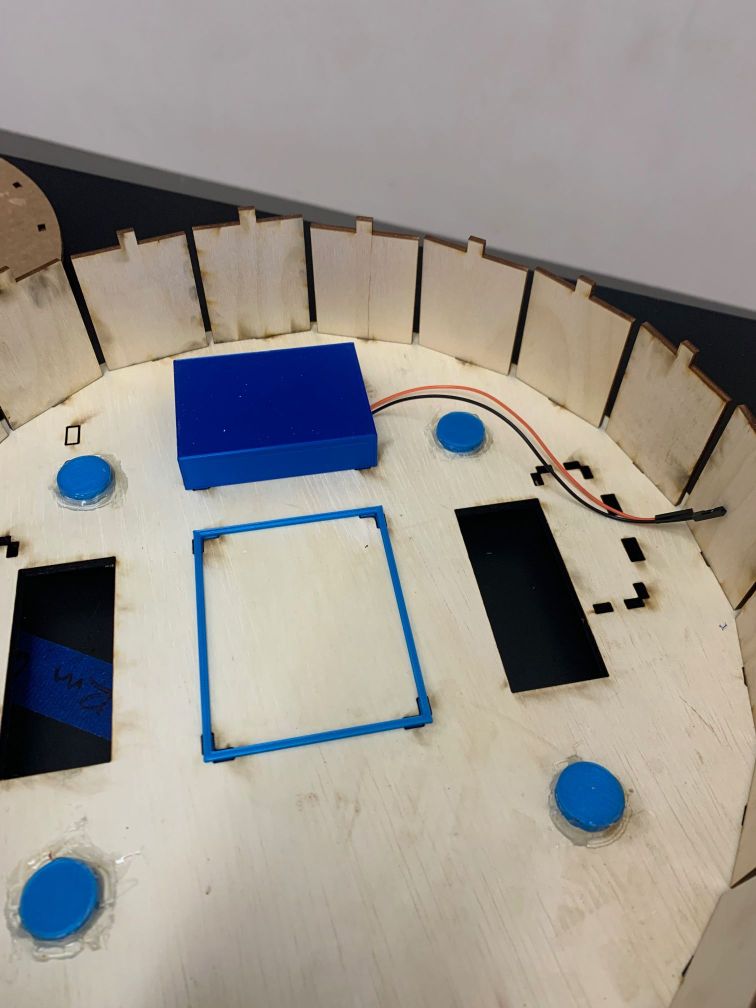
Finally, I moved on to my main car design. I cut out the same pieces as the bottom, but out of 1/8 plywood. I also cut out the top out of 1/8 acryllic. I then assembled all my 3D prints and electronics into my car design.
I started with the bottom and sides, which I cut on our lab’s laser cutter.
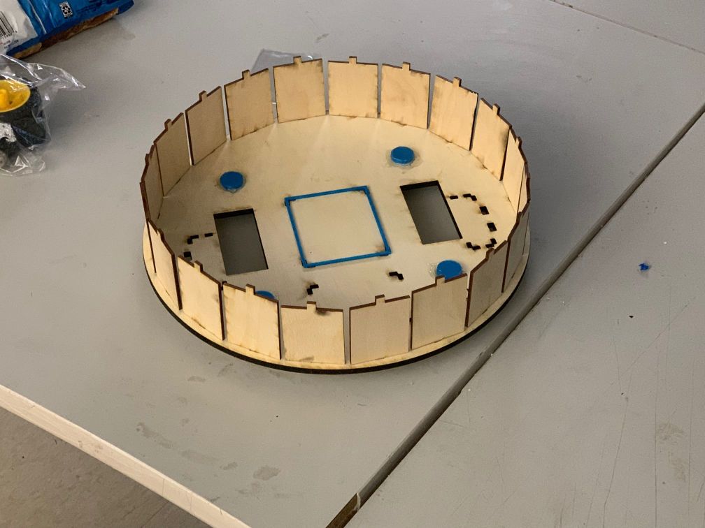
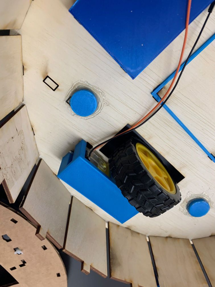
Next, I added the 3D prints for motor, board, and battery cases.
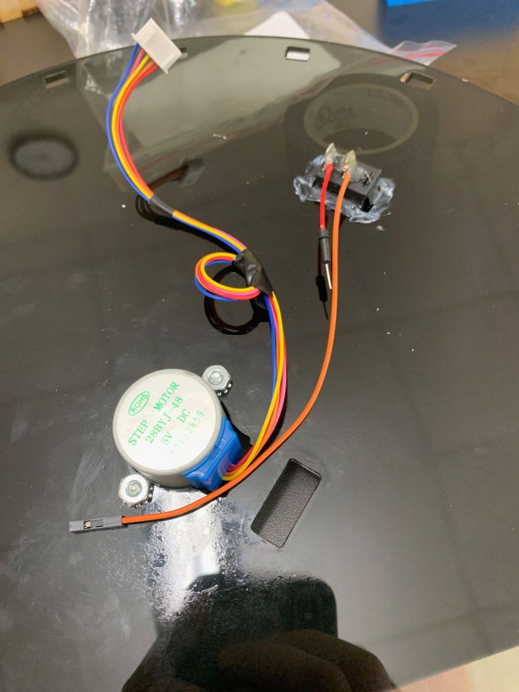
Finally, I laser cut the top and managed the cables. I laser cut a mount for my stepper motor, a slot for wires to run through, and a power switch so that I could turn off and on my project without opening the top.
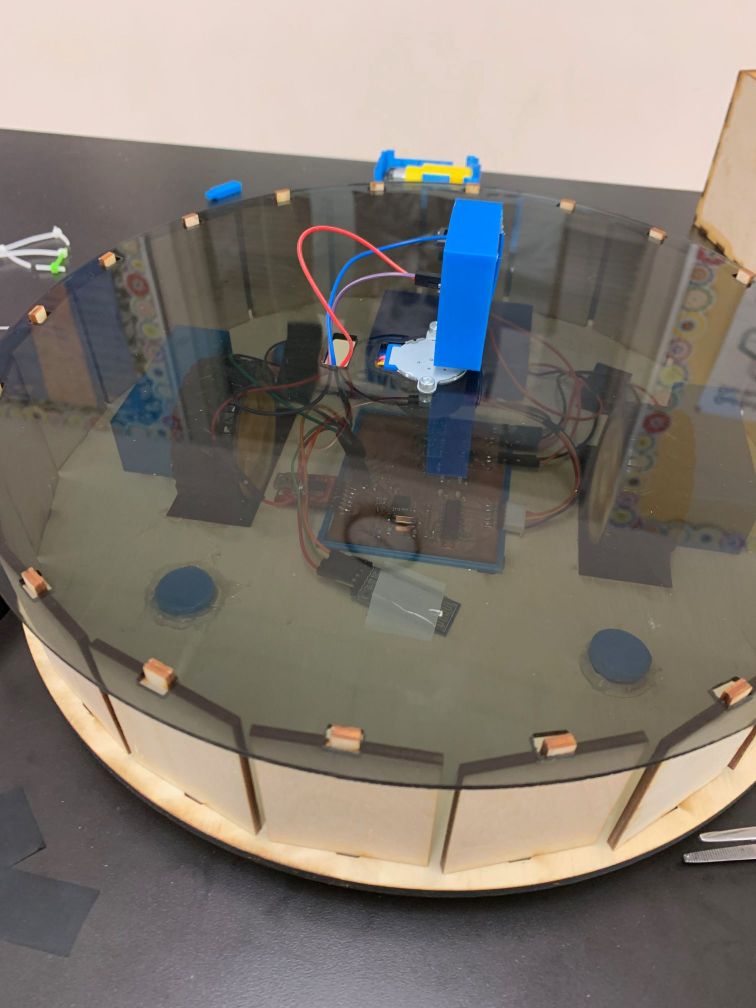
With the main body complete, I moved on to testing.
Testing
I immediately noticed a few issues with my robot. First, my sensor was detecting the front of the car. This is because the VL53L1X distance sensor has a field of vision of 26 degrees. To fix this issue, I reprinted a case that included a 13 degree upwards angle. The next issue was my wheels did not grip the ground well. This is likely due to the quality of the wheels and how they pick up dust fairly easily. I fixed this issue by slowing down the motors to account for slippage and dividing speed into 2 variables for each wheel because I noticed one wheel was slipping more than the other.
My project is still fairly inaccurate. The main issue is that even with the reduced speed, the wheel still do slip, and the car gets more inaccurate as it moves. The scanning feature also has a few issues, the main one being that I cannot route the cables running from my sensor without tangling them around the stepper, so I have to run it 90 degrees at a time. I also still have times where the sensor detects the edge of the car, so I will have to increase its angle some more. However, this affects the accuracy of the sensor, since the laser would travel a longer distance at a higher angle to reach a vertical target. I could mount it towards the edge of the car and only look in the front 180 degrees, but this would further complicate the point mapping equations.
Overall, I am happy with the functionality of my final product. If I had more time, I would make a few changes to the design, such as finding a better way to route and manage cables, since I was taping them down at points, and finding a solution to the sensor and wheel issues.
Questions answered in previous weeks
What will it do?
For my final project, I wanted to challenge myself on the software and hardware side of things, rather than the CAD and mechanical aspects. My car’s main purpose will be to map out a room. It will have a distance sensor, a main board, a bluetooth chip to communicate to a computer, and motors to drive itself around. It will drive around a room, take input with the distance sensor, and store these points in its memory. It will then upload these points to a computer via bluetooth, which will map the points in a display.
Who’s done what beforehand?
In terms of the car design, previous student and teacher Will Rudolph created a drawing car. The car had a pen on the bottom compared to my distance sensor on the top, but it had many of the same components. I will keep his design in mind while workign on the mechanical aspects of my project. The Roomba vacuum cleaner has a similar function to my project, as it has the ability to map and store a room as it cleans.
What will you design?
I will design the electronics for my car, the main car body, and I will develop the software that controls the car. The electronics will include the sensor board, main board, and any breakout boards I need for motors or power. The car design will include casing for the electronics, a system to spin the sensor and sensor board by the stepper motor, and a way to balance the car (which will have 2 wheels). I will design my car after a Roomba since they have the ability to map rooms. The software will include manual control of the car, a way to calculate and upload the points, a way to track the car as it drives throughout the environment, and a way to display the points.
What materials and components will be used?
The electronics components that will be used include some darlington transistor breakout boards and chips for motors, a voltage regulator system, components for the ATMega328, and headers for an FTDI chip and bluetooth chip. The base of the car will likely be made from 1/8 plywood to minimize weight, while the frame will be made from 1/8 acrylic to improve the aesthetic. I will 3D PLA components for balancing the car and for holding motors and electronics in place.
Where will come from?
Most of the electronics components can be found in our lab, but I ordered some breakout boards and chips during input and output devices weeks from Pololu and Texas Instruments. The physical materials can be found in our lab- we have plenty of 1/8 plywood and acrylic as well as 3D print materials.
How much will they cost?
The electronics components in our lab were very cheap; the components used in my final board amounted to a few dollars. The breakout boards I ordered were more expensive; the motor driver boards were 3.50 each and the sensor breakout board was 12 dollars. The 1/8 plywood and acrylic will not be expensive either, and they will not cost more than 20 dollars.
BOM:
| Part | Total Cost | Source | Quantity | Other Information |
|---|---|---|---|---|
| 1/8 in plywood | 5.00 | link | 1 12 x 24 | This will be cut into the bottom and sides of the car |
| 1/8 in acrylic | 8.00 | link | 1 12 x 15 | This will be cut into the top for the car |
| VL53L1X TOF Sensor | 12.00 | link | 1 | Distance sensor with range up to 400 cm |
| DRV8838 Breakout Board | 7.00 | link | 2 | Breakout board to control the DC motors |
| 28byj-48 Stepper Motor | 7.50 | link | 1 | Motor to spin the distance sensor |
| Geared DC Motor | 6.50 | link | 2 | Motor for moving |
| HC-05 Bluetooth Chip | 10.00 | link | 1 | For networking between computer and car |
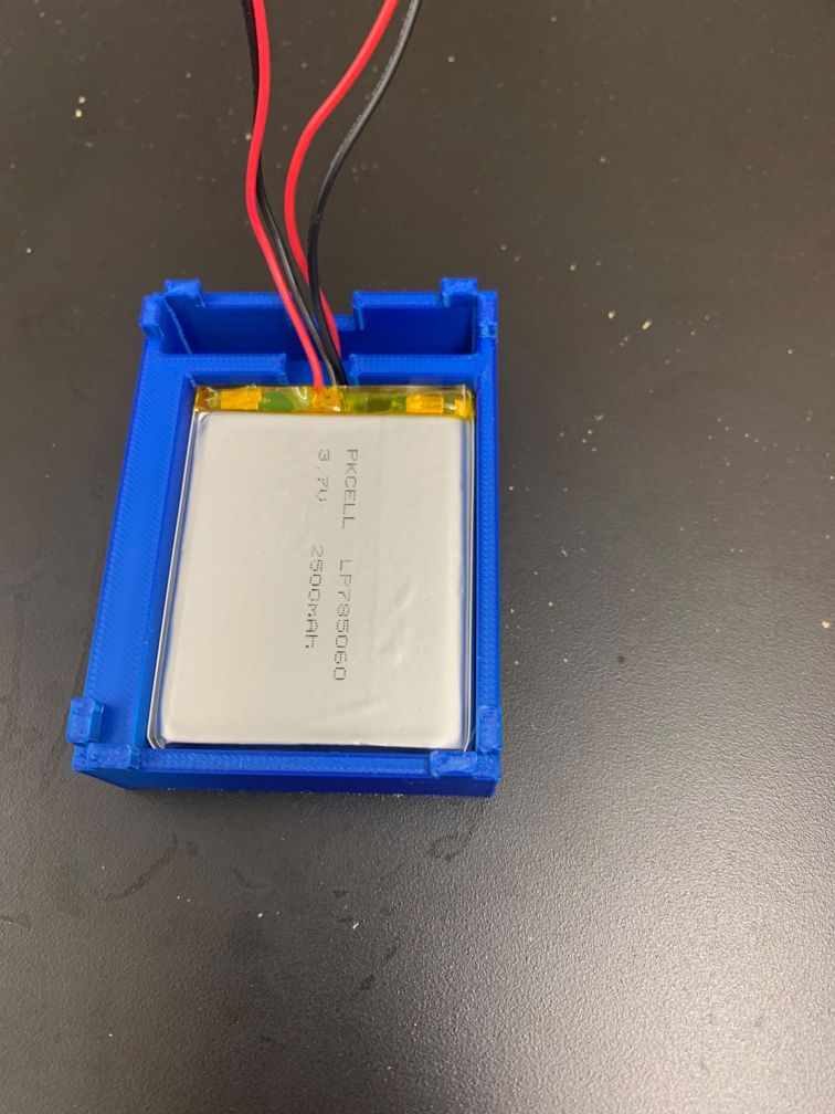
| 3.7V Lipo Battery | 22.00 | link | 2 | These will be connected in series to produce 7.4 volts |
| 1 kg 1.75mm PLA | 25.00 | link | 1 | This will be used to print out the different components inside the car |
| Total Cost: | 103 |
What parts and systems will be made?
There will be 2 main systems in my project. The main system is the car. This includes the physical aspects of the car, such as the frame and housing for electrical components, as well as the software. The other system is the computer and interface that will control the car. The two systems will be connected via an HC-05 bluetooth chip, which will transfer data between the systems.
What processes will be used?
I will use computer controlled cutting, 3D printing, electronics design and production, embedded programming, and interface programming to complete my project. I expect the most difficult task will be the embedded programming aspect due to the complexity of my task. I will laser cut the frame of the car out of 1/8 in wood and acrylic. I will 3D print different small components inside the car, such as electronics cases, pieces for balancing the car, and a case for my sensor board. The electronics design and production elements includes a main board with components for voltage regulation, FTDI and HC-05 headers, motor breakout boards, and the ATMega328 microcontroller, and a sensor board with an ATTiny1614 microcontroller and headers for the VL53L1X time of flight sensor. These two boards will be networked via software serial to input sensor data.
What questions need to be answered?
I will need to determine the best solution to the programming problems I am likely to face, including how to calculate, communicate, and display the data, and how to accurately keep track of my own location throughout the operation. I will also have to find a way to deal with slippage if I find it is an issue. If the motors slip while the car is running, it will no longer be able to keep an accurate location, so this could be a critical issue.
How will it be evaluated?
My project will be evaluated by how accurately it is able to map and display its enviroment, as well as how accurate and precise it is about its own location.
What are the implications?
The tracking and mapping portion of my project is known in the robotics engineering fields as SLAM, simultaneous localization and mapping, or SPAM, simultaneous planning and mapping. My robot, even though it does not incorporate the autonomous features, it does incorporate the basic functions of tracking its position and mapping the environment. It is possible to adjusts and incorporate other features, such as autonomous control, to create a basic SLAM robot.
Files
My files for my final project can be found in this zip file.

This work is licensed under a Creative Commons Attribution-NonCommercial 4.0 International License.