9. Machine and Mechanical Design
The assignment for these two weeks is to create a machine that includes a mechanism, automation, and actuation. I must be able to build the mechanical parts and operate them manually. The assignment is a group project, so I will be working with students from our lab to complete this assignment. Our group includes Jack Hollingsworth, Miller Workman, and James Rutter
Foreword
Due to a variety of issues in our group, the work documented below is not at a quality I would be proud of. Our lab, Charlotte Latin, usually has all the students work in one large group for this week, but due to the large amount of students this year, we were split in half across two projects. Furthermore, about halfway through the assignment, two of our groupmates quit for reasons out of our control, leaving me and my teamate Jack Hollingsworth. We were unable to finish the week on time, and we had to finish in the week after our final project presentation. However, we still worked hard and put a large amount of time into this project. This page will document the development of our pinball machine.
Defining project idea
Our group decided to design and create a custom pinball machine. I was inspired by a pinball machine owned by our teammate Jack Hollingsworth. I also found a similar project to our own, which also helped us while working out our electronics and design needs.
BOM
I started the week by knocking out what parts I would use. I created this BOM to narrow down our requirements. Some of the electronics were the same as the tones in the similar pinball machine project since they seemed like they would work.
Early CAD
We started by designing the basics of how the pinball machine would look. Miller Workman designed the size of the pinball machine, included joints and legs, and some other pieces like buttons. The buttons were just for aesthetic- the buttons I chose can just be screwed in- but they were the correct size.
While designing the shape of the final product, I started designing some of the mechanics that would be used in our machine. I decided to include a bumper element that would push the ball down and away, as well as the flipper mechanics.
3D design- bumper
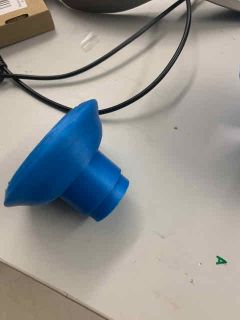
I started by designing the bumper element. I first designed the main body, then a shell that would actually push down and “bump” the ball. The first design had 2 rods that would attach to the shell and to a solenoid that would be located under the playing field, and the second one had 3D printed parts that would go through the base.
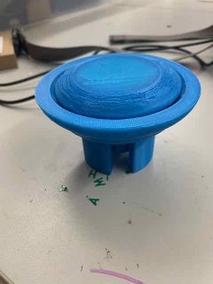
First Design:
Second Design:
3D DESIGN- paddles
Next, I designed the paddle mechanics. I designed it so that when the solenoid fired, it would push a 3D printed part, causing it to rotate. A metal rod attached to the 3D printed part would then go up to the top of the playing field, where the paddle would be attached. The paddle would then rotate. When the solenoid is relaxed, a spring attached to the part will compress, causing the pieces to rotate to their starting places.
3D DESIGN- Spinner element
The final element I decided to include in the playfield was an acrylic piece that would reside somewhere towards the center of the playing field. This piece would constantly spin in a circle, adding to the complexity of play. I designed this piece in Fusion and laser cut it out. It turned out well, and I was able to connect it to a servo motor and our board:
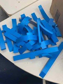
ASPIRE- creating tool paths for sides
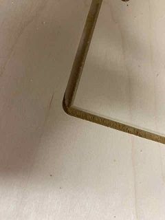
After finishing the early cad work, I then milled them out. I started by turning them into 2D sketches, putting them into Corel to clean them up and turn them into SVGs, and finally turning the SVGs into tool paths in Aspire. I created tool paths for each side of the frame of the pinball machine. It included a slot cut for the paying field to slot into, joints, and holes for buttons. Miller and I worked together in the machining process, and cut out the parts he designed earlier in the week.
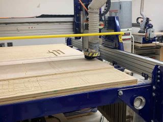
MACHINING THE PARTS
Next, I cut out these parts on our lab’s Shopbot. I cut out the frame in wood because it is strong yet fairly cheap. I followed our lab’s workflow to operate the machine and cut out each of the pieces.
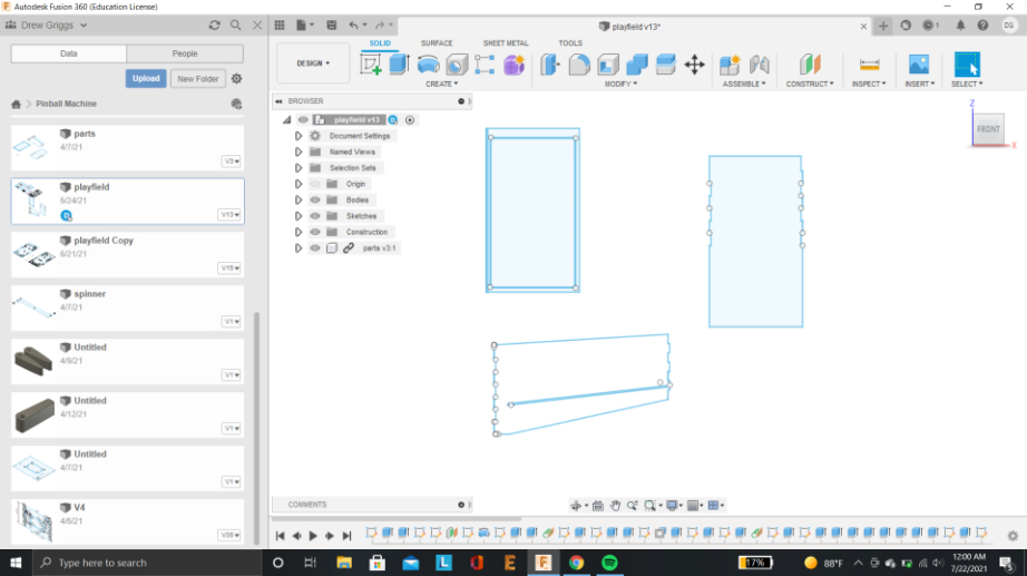
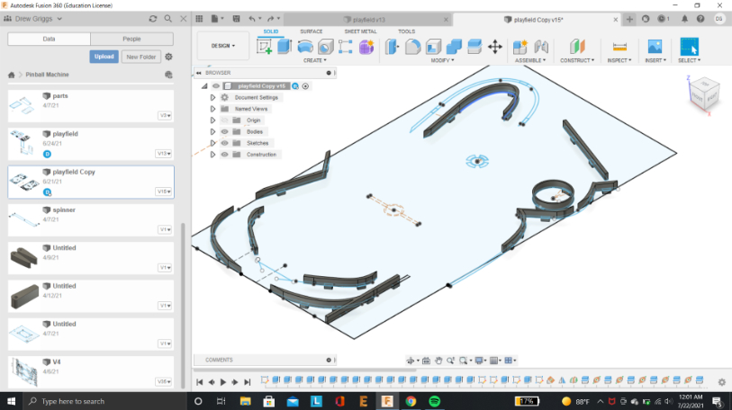
2D DESIGN Playfield CAD
Next, I designed the actual playfield. While machining, I accidentally cut out the front piece mirrored horizontally, so the hole for the launcher was actually on the left instead of the right. To resolve this issue, I simply mirrored our playfield after designing it so it would still work.
I then milled the playfield out with our Shopbot after converting the 2D sketch into a tool path through Corel Draw and Aspire. It milled out very nicely:
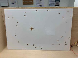
Unfortunately, there were a few errors with our playfield, including holes for rails being too tight, no holes for motor mounts, and some others. I will not be able to use the playfield, so I will laser cut it out of acrylic instead.
3D DESIGN- routers
My playfield design included quite a few holes that would hold routes for the ball. I designed features that would stick through the playfield in these holes that would route the ball above the playfield. I had many of these features, and after splitting the bodies so they could fit on our lab’s printers, I had 24 bodies in total. After adding as many features as possible to the print file, I ended up with about 8 5-6 hour prints.
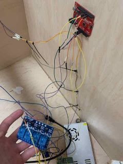
ELECTRONICS WORK- relays, solenoids, and Arduino
While milling the parts, our group continued working on electronics. I decided on using a relay board to control the bumper solenoids since they would need to be triggered at certain times and to hardwire the buttons to the paddle solenoids. I also decided on using touch sensors to detect where the ball is in order to update the score. I was able to control the solenoids in this way.
Jack Hollingsworth and I worked together on the electronics. We used our 12V power supply for everything in our machine, but our Arduino and LEDs needed 5V to operate, so I started by creating a simple power regulator by using a 12V-5V regulator.
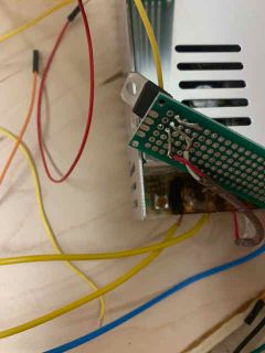
This provided enough current for the Arduino to function, but after some testing, I saw that the LEDs would sometimes turn off if left on for some time. I suspected this was because we weren’t getting enough power to our 5V components, so I created a second power regulator board and connected the 5V lead in parallel. This provided enough current, and the 5V components were functional.
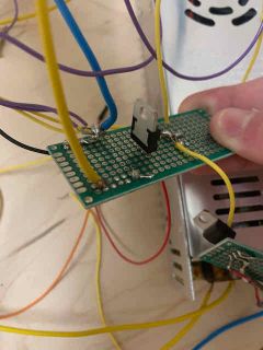
I connected everything using mostly proto boards and jumper cables. I will hot glue everything in place in order to prevent shorts once I have a functional final product.
Next, I connected the motors to the Arduino with the relay. First, I learned how a relay works. It has a small solenoid, and when it receives a signal, it will trigger the solenoid to flip a switch. The relay has 3 leads, a common, one that is normally connected (NC) to common, and one that is normally not connected (NO- normally open) to common. The solenoid will reconnect the common from NC to NO, thus flipping a switch.
We will use this to control our solenoid for the bumper element. Our paddle solenoids can be hard-wired to the side buttons, but I need to take input in order to adjust the score with the bumper. The bumper will be normally open but when I detect the ball near the bumper, I will close the solenoid connected to it, which will pull the bumper down.
The Arduino side of the relay board connects to 5V, while the solenoid side connects to 12V.
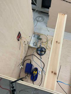
We assembled our electronics around our frame so I could easily get the correct length wires.
Now, all that is remaining is to laser-cut the acrylic playfield, 3D print some motor mounts, and assemble and test the machine.
Finishing the Pinball Machine
Unfortunately, we ran out of time during the two weeks alloted for mechanical and machine design. We picked back up after our final project, but 2 members of our team had quit fab, so it was just me and Jack Hollingsworth. With the large scale of the machine, it was difficult to get a functional pinball machine built in the limited time between our presentation date (June 16) and the final due date for global evaluation (June 21).
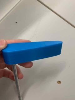
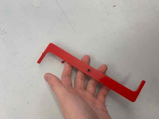
Mechanical Parts
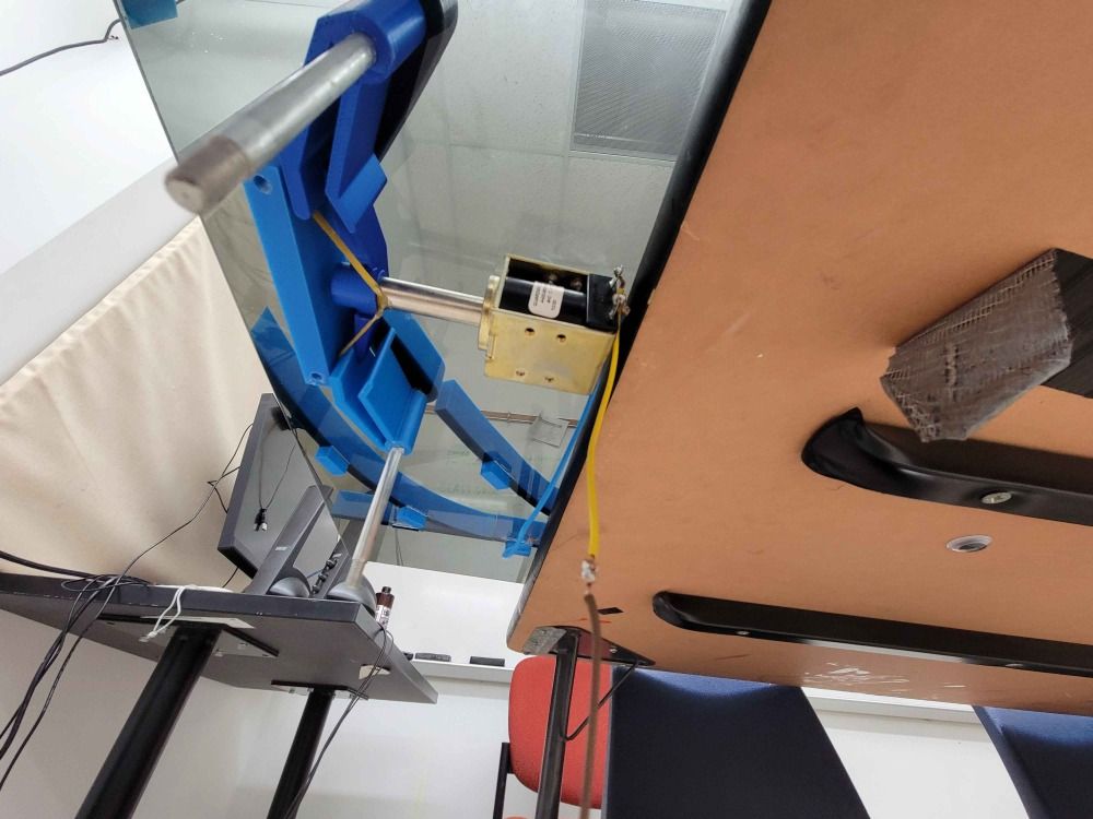
I started off by working on the mechanical parts for our pinball. We had misplaced one of the rods for the solenoid, and we couldn’t find a replacement, so I designed it around one rod. I desinged this system in Fusion 360:
The idea is that the solenoid rod would mount to the middle piece and would be pulled back, causing the two pieces on each side to be rotated. This rotation would rotate a rod connected to the paddle on the top of the playing field.
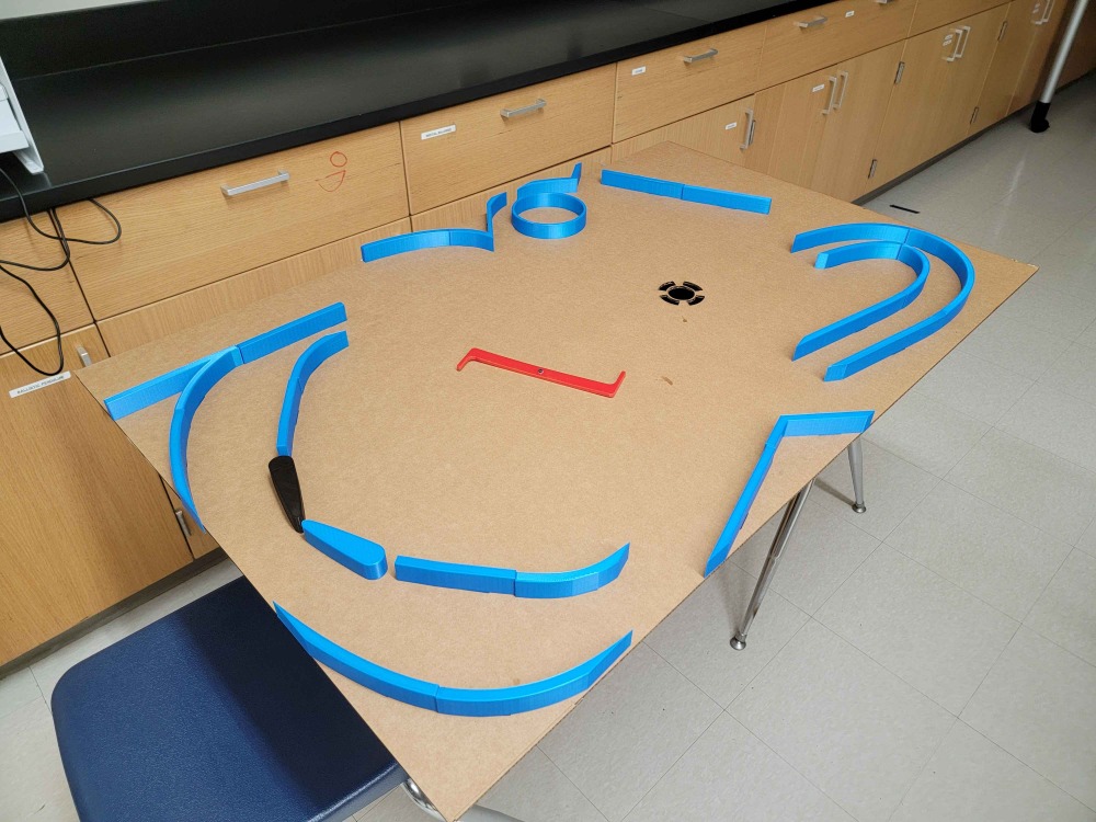
Playing Field
Next, I finished the design for the acryllic top and cut it out. I started with a cardboard test cut to make sure everything would fit, and after confirming this, we cut out of acryllic.
Software
To run the pinball machine, we used some very basic software to trigger the mechanism when a button is pressed and to run a neopixel strip. My teamate Jack Hollingsworth worked on the neopixel part, while I worked on the solenoid part. This is the code I wrote to preform this task. It is very simple, and it just writes to a relay.
#define bpin 8
#define solenoid 3

void setup(){
  pinMode(bpin,INPUT_PULLUP);
  pinMode(solenoid,OUTPUT);
}

void loop(){
if(digitalRead(bpin) == LOW){
  digitalWrite(solenoid,HIGH);
}
else{
  digitalWrite(solenoid,LOW);}
}
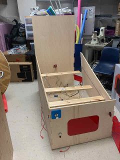
Assembly
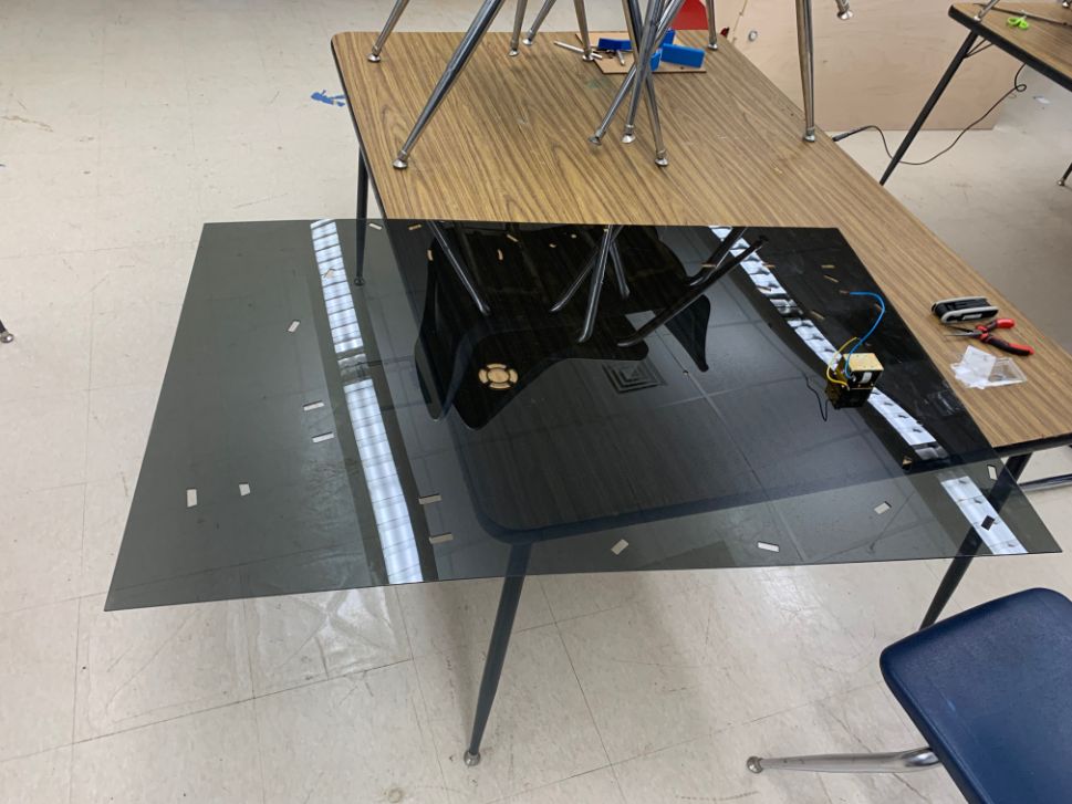
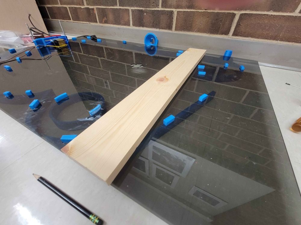
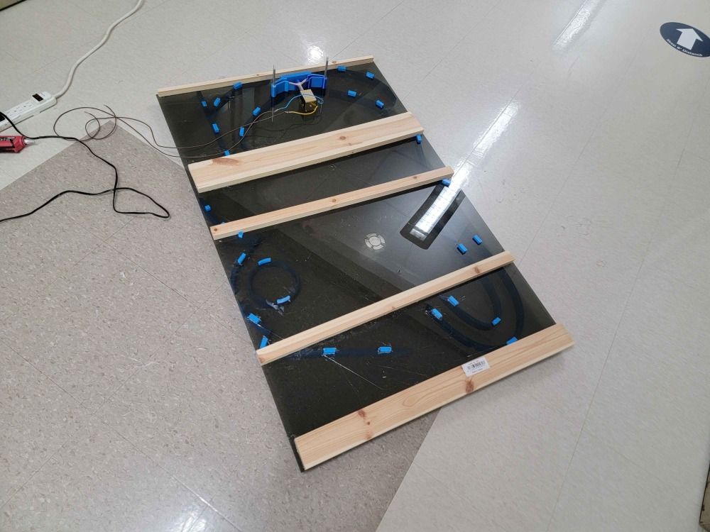
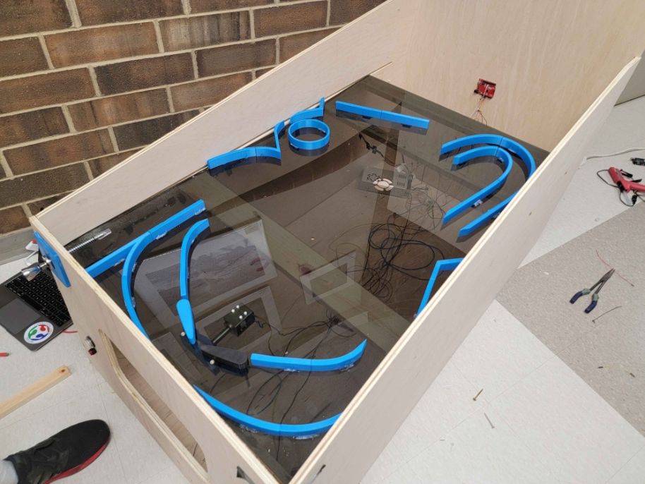
We then assembled the playing field. This part was very time consuming, since we had a very large design with only 2 people to work on it. We printed the mechanical parts on our lab’s printer farm, and were pleased to find that they worked. We continued with the other 3d printed pieces, and used screws to attach the solenoid. Next, we attached some wooden beams to the bottom of the acryllic playfield, and prepared to finish the assembly.
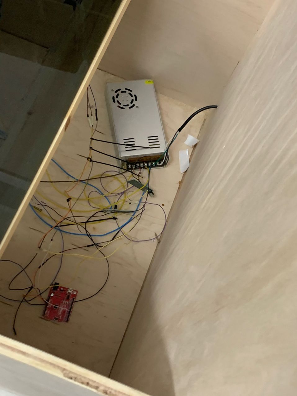
Before attaching the top, we first implemented the electronics. Due to the immense size of the project, it was difficult to efficiently route all the electronic components. We needed 2 5v voltage regulators to support enough current for our project, 2 arduinos to control the neopixels, buttons, and solenoid, and the scale of the project made it diffucilt to route everything in an organized way. Due to this, our wire management was very lackluster and disorganized, but it was still functional.
To attach the playfield, we drilled through the frame into the wooden beams to support it. The beams also helped keep the surface level and secure- 1/8 in acryllic is very flexible and weak, and the material was already fairly warped before we started cutting it.
Testing
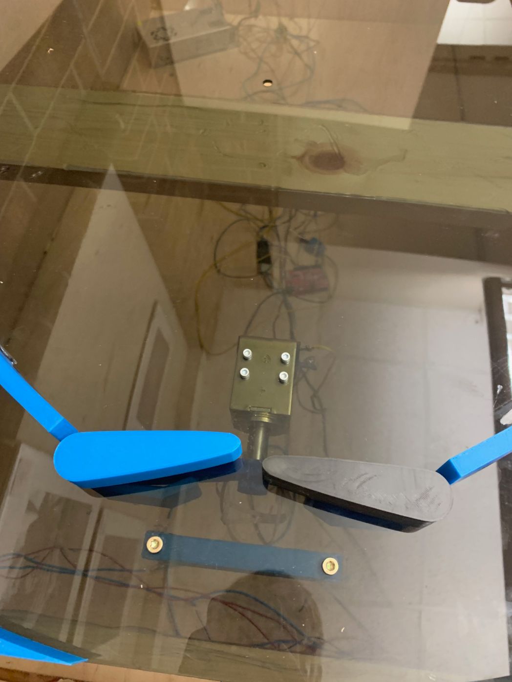
We then tested the pinball machine. First, we manually operated the machine. The video below shows us operating the flippers manually.
Next, we tested it will a variety of balls we could use as pinballs. However, after using the machine, we found that the paddles were generating very little force. This is most likely due to the inefficient transfer of energy and the large weight of the entire mechanism. First, the solenoid transfers energy into an attachment, losing a bit of kinetic energy in the process. Next, the attachment runs into two pieces, causing them to rotate. These two pieces each attach to a metal rod that attaches to a paddle on the surface. Throughout this entire process, a large amount of kinetic energy is lost through friction. Another issue we noticed is that the force of the friction is so large, we needed 4 rubber bands to reset the paddles. However, the solenoid was unable to actuate under the added pressure from these rubber bands, resulting in a one-time-use paddle. Obviously, pinball is impossible to play under these conditions.
This is the final assembly of the pinball machine. To learn more about the process developing this project, please visit our group site.
The files from this week can be downloaded here.