Introduction.
In this I met and explore information related to laser cutters, I find it very interesting
things that can be done or rather cut with such precision. The vinyl cutter is a machine
that is mainly used to trim vinyl and other materials in many shapes or letters, depending
on the needs of use.
The vinyl cutter is not a very large device; You can connect to a computer with a cable to
give cutting instructions.
To make the cut in both vinyl and laser it is necessary to use software to model the cut,
there is something very interesting called parametric design, which allows you to design and
assign values to your dimensions through the use of variables, which is nothing more than
a kind of excel sheet that allows changing values. Among the software that allows this is
freecad, autocad, fusion, rhino and others.
Laser cutter characterization.
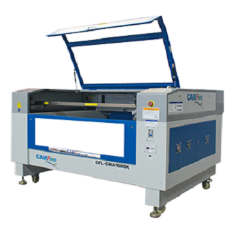
One that is used is the CAMFive
CFL-CMA1080K laser cutting recorder, which has a work area of 1.00 x 0.80m, the
table can automatically raise and lower, in addition to having a rotating accessory with
which it is possible to cylindrically engrave objects.
Laser cutting is a type of thermal separation process. The laser beam impacts the
surface of the material and heats it with such force that it melts or vaporizes by
full. Once the laser beam has completely penetrated the material at one point,
The actual cutting process begins. The laser system follows the selected geometry and
separates the material in the process depending on the application the use of process gases
It can positively influence the results.
Soft material |
Cut |
Graven |
|---|---|---|
| Paper | yes | yes |
| Paperboard | yes | yes |
| Foaming | yes | yes |
| Felt | yes | yes |
| Cotton fiber and mixed fabrics | yes | yes |
| Thick synthetic fibers fabrics | yes | yes |
| Synthetic fabric Lycra and thin | yes | no |
| Leather (Natural leather) | yes | yes |
| Leather (Synthetic leather) | yes | yes |
| Rubber (rubber or rubber) | yes | yes |
| Cork | yes | yes |
Hard materials |
Cut |
Graven |
|---|---|---|
| MDF | yes | yes |
| Wood | yes | yes |
| Foaming | yes | yes |
| Triplay | yes | yes |
| Plastic | yes | yes |
| Acrylic | yes | yes |
| Glasses and crystals | no | yes |
| Ceramics | no | yes |
| Marble, Onyx and other rocks | no | yes |
| Tile | no | yes |
| Metal (apply special resin) | no | yes |
Technical specifications
WEIGHT: 185 Kg (407.85 pounds) DIMENSIONS: Width: 1.35 meters (53.15 ") Height: 1.17 meters (46.06") Depth: 0.99 meters (38.97 ") To make use of the laser cutter there must be a hygiene and safety plan and must always be respected, to avoid accidents and to ensure the proper functioning of the equipment. The first step is to verify that it is connected to the power, then activate the voltage regulator's power switch, set to 216V input voltage and 220V output voltage. Then, turn on the machine, releasing the emergency stop button and insert the key. Turn the intensity knob and press the laser button, which will turn on white, indicating that the laser is active. From here you must be very careful, because the laser is not visible. To make a cut or engrave, there are two options: upload the file directly to the machine through the USB port or through software that controls the machine. Files must be in .DXF format.
Before making a cut, take into account the following data, as you can see both the
speed and the power range depend on the type of material and its thickness.
Remember that these are suggestions of standard measures to program cutting or engraving
jobs, but depending on the type of edge you want in the design. These parameters will
also vary, as the ray burns or sublimates, leaving a more intense color in the contours
of certain materials such as wood.
|
CUT |
RECORDED |
||||
|
Material |
Thickness in mm |
Speed in mm / min |
Power range |
Speed in mm / min |
Power range |
|
MDF |
3 |
15-20 |
50-60 |
200-400 |
30-50 |
|
6 |
10-15 |
60-70 |
|||
|
9 |
5-8 |
80-85 |
|||
|
12 |
3-8 |
85-90 |
|||
|
Acrylic |
3 |
10-20 |
60-65 |
200-400 |
20-35 |
|
6 |
6-10 |
60-70 |
|||
|
9 |
5-7 |
80-85 |
|||
|
12 |
2-5 |
92-93 |
|||
|
18 |
1-2 |
85-90 |
|||
|
Bond paper |
NA |
100 |
15-20 |
600 |
15-20 |
|
Cardboard |
NA |
50 |
30-35 |
600 |
40-45 |
The process of laser cutting
Laser cutting is based on the interaction between a focused laser beam and the workpiece. In
order for this process to be carried out safely and precisely, a multitude of components and
auxiliary means come into play in the laser beam and in its environment, which are clarified
in the following graphic.
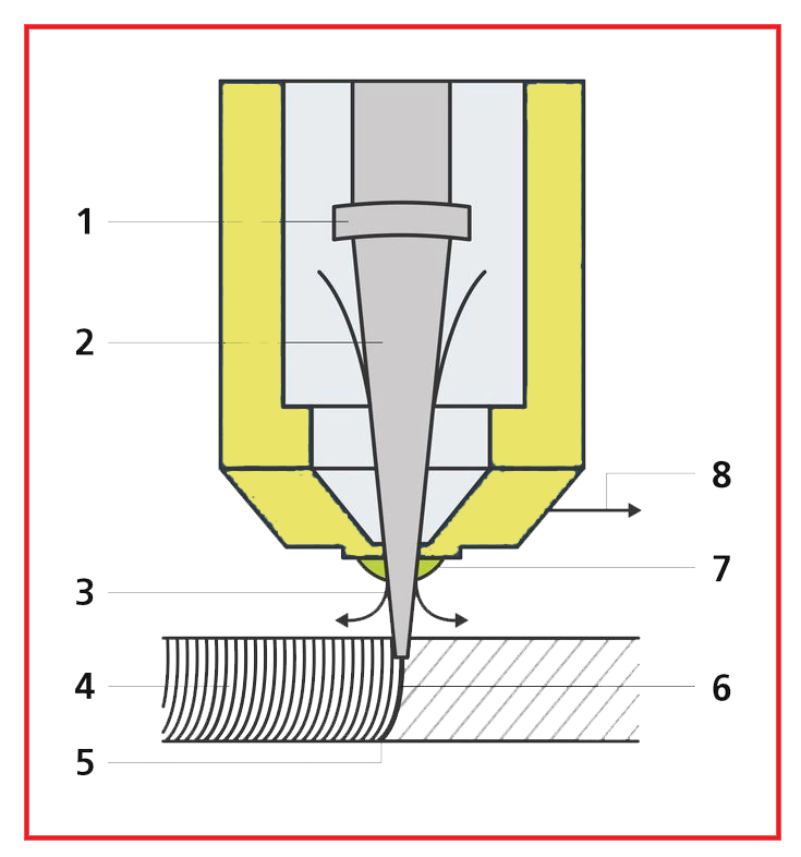
- Focusing optics: mirror and lens optics focus the laser beam on the machining point.
- Laser beam: the laser beam strikes the part and heats it until it melts or evaporates.
- Cutting gas: with the help of cutting gas, the generated melt is blown out of the cutting groove. The cutting gas exits the nozzle coaxially at the same time as the laser beam.
- Cut grooves - In laser cutting, the cut edge receives a characteristic groove pattern. With a low cutting speed, these grooves run practically parallel to the laser beam.
- Casting: the laser beam (concentrated laser light) is guided along the contour and melts the material locally.
- Cutting face: On the cut piece, the width of the cut groove just barely exceeds that of the focused laser beam.
- Nozzle: the laser beam and cutting gas strike the workpiece through the cutting nozzle.
- Cutting direction: by moving the cutting head or the workpiece in a certain direction, the cutting groove is produced.
VINYLCUTTER
Silhouette Curio
Features
It is a compact vinyl cutter is ideal for a wide variety of applications including labels,
labels, stickers, stickers, vehicle graphics.
- Silhouette Curio Digital Crafting Machine
- Small 8.5" x 6" Base (Includes 4 Platforms)
- 8.5" x 6" Cutting Mat
- 8.5" x 6" Embossing Mat
- 12 - 12" x 12" Assorted Oracal 651 vinyl permanent sheets
- 1 -12" x 12" Transfer Paper Sheet
- 24 Sketch Pens
- Pixscan Mat
- Wide Emboss Tool
- Fine Emboss Tool
individual assignment
-
First steps:
- Download and install the software for the cutter.
- Connect the cutter to the computer using the included usb cable.
-
individual assignment: cut something on the vinylcutter
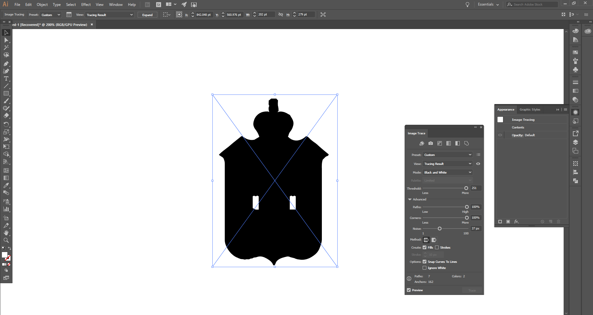
To create the vector image I decided to use the shield of Tabasco and use Adobe Illustrator
Adobe Illustrator is a vector graphics editor in the form of an art workshop that works on a drawing board, known as a "workbench" and is intended for the artistic creation of drawing and painting for illustration, to create and design images.-
To create the model for cutting vinyl.
-
I imported a picture and then using the "Image Trace" tool and after some
testing with the parameters, I got the vector.
In the presets choose "black and white logo" and we will see the change that occurs in the image. Generally with a B / W image we will not have to adjust any parameters. -
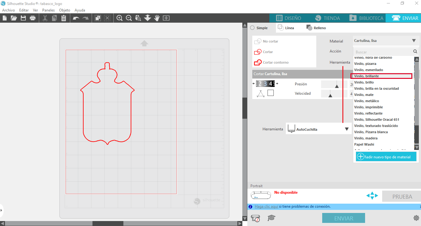
For the vinyl cutting, the silhouette studio software was installed to
send the
image to the cutter.
Then I cut a piece of vinyl to make a test. The knife is adjusted.
-
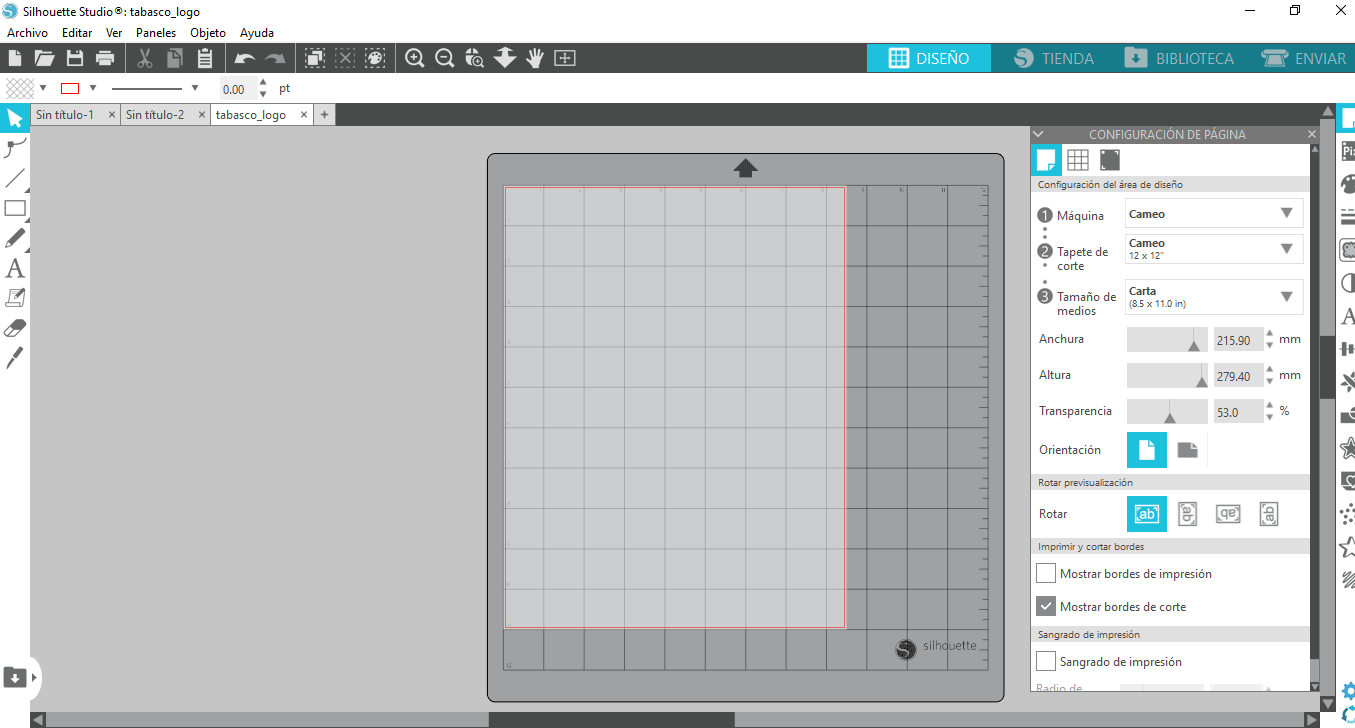
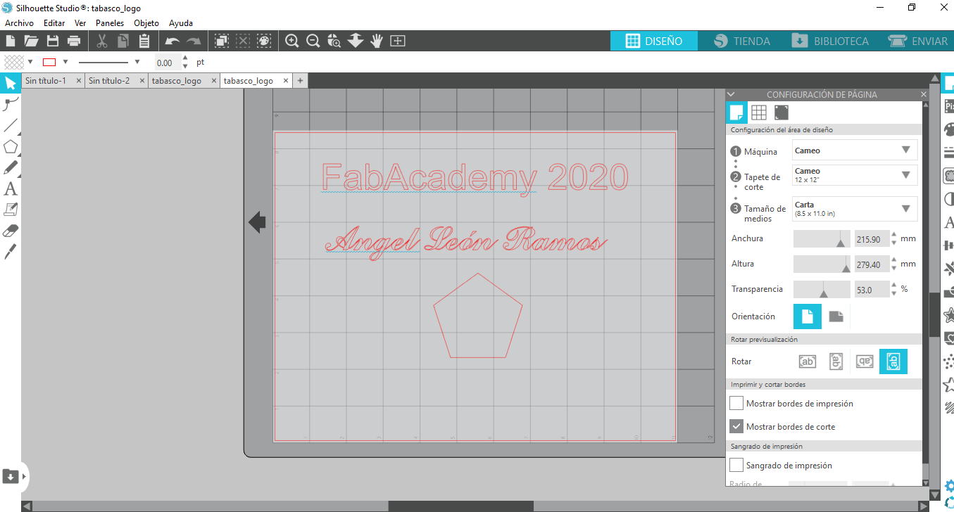
The first step is to open the silhouette studio software, now in the
configuration of the design area you have to select the machine,
which in this case is "cameo", if you are going to use a mat, you
must select the measurement in the mat. case 12x12 in) or none in
case of not using the mat, the next data is to establish the size of
media to be placed (it can be a custom size) in this case letter
size (8.5x11.0).
-
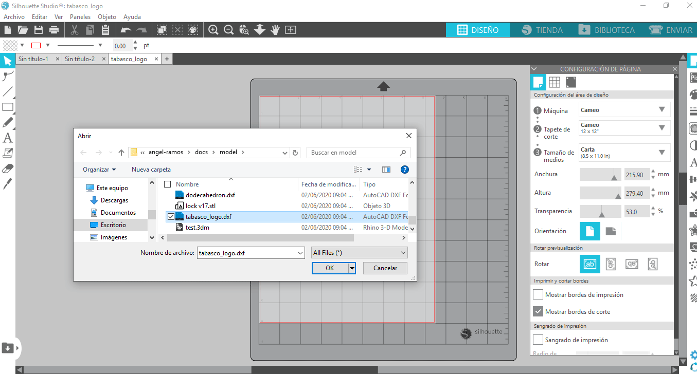
Now in the file menu, select open and locate the dxf file that we
are going to use.
-
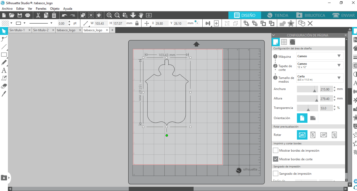
In case the image is very large, it can be reduced, to select the
image and use the tool "lock selected shapes" that is to scale the
image.
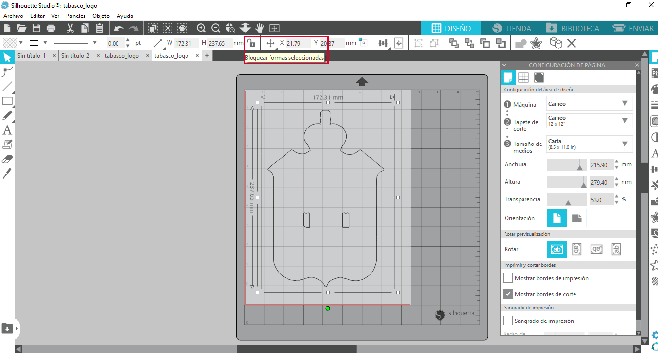
-
To change the dimensions it is only necessary to drag with the mouse
and set the desired measurements, you can still change the size of
the media if you consider it. If there is something in your image
that does not require, just select with the mouse and delete.
-
Now in the send view we select everything and we click cut, now in
material we select glossy vinyl, when choosing the material
automatically it sets the value of the blade, the pressure and
speed.
-
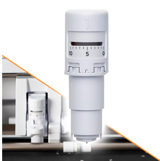
Before cutting, it is necessary to verify that the blade is already
in place, in this case a Silhouette self-adjusting blade is used,
It allows cutting different types of materials, and is adjusted by
selecting the type of material from the software.
It is installed in carriage 1 (left) and adjusts automatically, you just have to indicate the material to be cut in the Silhouette Studio® software and the plotter will do the automatic adjustment.
-
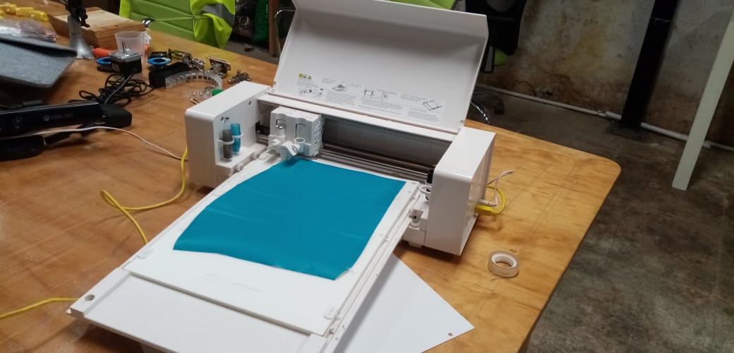
The material configuration was verified and sent to the vinyl
cutter, because it was observed that the blade was being forced, the
cut was canceled and the depth was modified.
-
Subsequently the silhouette portrait was used, it has a blade that
automatically
changes
the depth, simply in software it is chosen (image knife_automatic),
when
making
the cut
it was observed that the blade is worked, probably due to the
vectorized
image
It has a
double contour, so a test was carried out by drawing directly on the
software a
pentagon
and a circle to evaluate the cut and it was determined that it is
not an
image
problem
but is due to the curves it has.
-
Vectorized drawing that later became a decal.
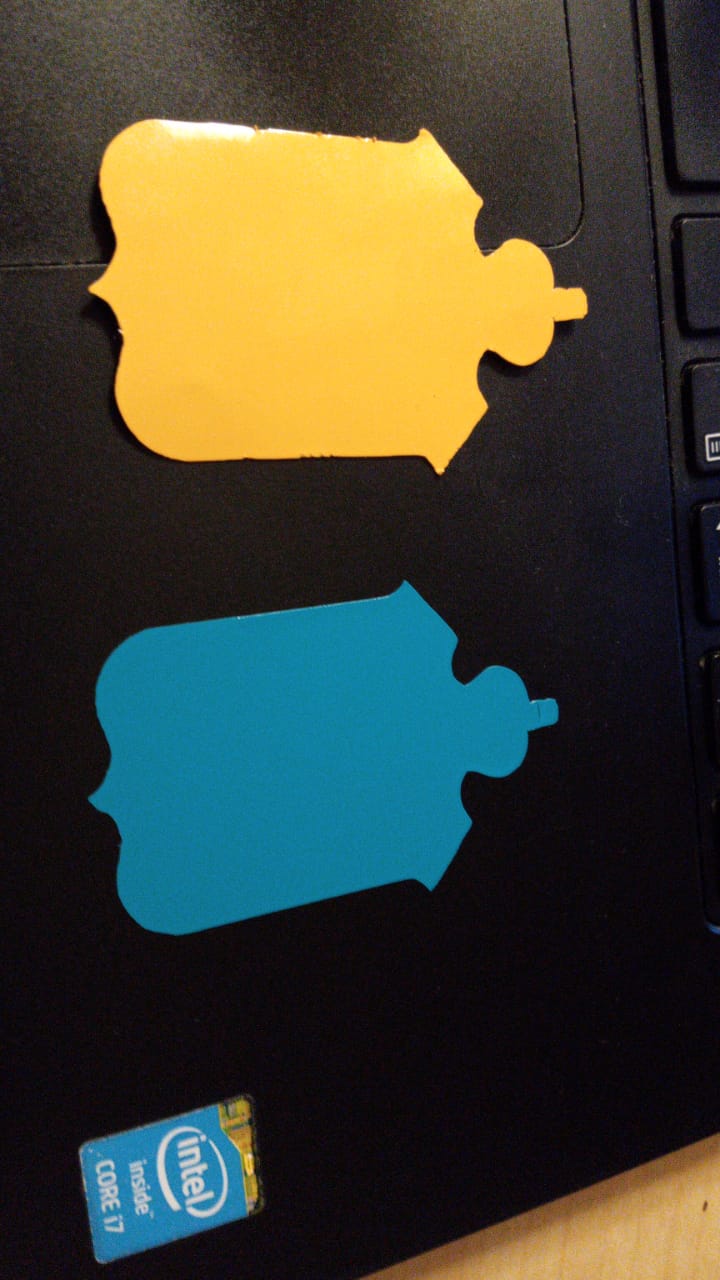
Material:
adhesive vinyl paper
scissors
adhesive tape. -
After the cut I was testing the software and with the tools you can
design to make the cut, it is interesting. Figures, lines and
writing can be drawn.
-
Should consider:
The best way to avoid wasting material is to make one or more small test cuts each time you insert the holder or cut new material. We should not assume that the recommended settings for any given material will always be correct. There are many factors that affect the way a material will be cut, such as the sharpness of the blade, the condition of the vinyl, the complexity of the design, exposure to moisture, and the color of the tint used on the material. If you can't get a good cut on the test, it will almost certainly not work well for the rest of your project.
Know the possible causes of various problems, such as: Identify in the cutter (the brand you use) the problems that may arise and learn what the possible causes are such as:
Nothing is cut or the force is too low; not enough blade exposure; the blade is too high on the material; the blade is chipped.
Partial cuts: the force is too low; the blade is too close to the material; the material is not stabilized; more than one pass is needed; speed is very high.
Tears in the material: too much force on the blade; the material has been exposed to moisture; the material is not suitable for cutting
The end point is off the starting point: the force is too high (less force and more passes are needed); the speed is too high; the material is not stabilized.
Rounded Corners - Blade offset is too low.
-
The first step is to open the silhouette studio software, now in the
configuration of the design area you have to select the machine,
which in this case is "cameo", if you are going to use a mat, you
must select the measurement in the mat. case 12x12 in) or none in
case of not using the mat, the next data is to establish the size of
media to be placed (it can be a custom size) in this case letter
size (8.5x11.0).
-
To create the model for cutting vinyl.
- individual assignment: design, lasercut, and document a parametric construction kit, accounting for the lasercutter kerf, which can be assembled in multiple ways, and for extra credit include elements that aren't flat
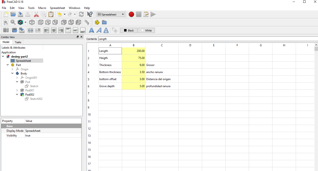
- The first parametric design was done using freecad and it consisted of a geometric figure with protrusions on two of its sides, the intention was to test the use of the parametric variables, that was quite simple, just add Spreadsheet that is similar to an excel sheet
-
There I defined the variables (alias) with their respective values, then added a
four-sided
figure and assigned the parametric values for width, height, thickness and
depth.

-
To create the parametric variables, you must select the "Spreadsheet" workspace
and create a new Spreadsheet, it is a sheet that can add variables and values
(you must assign an alias that is used to reference the value), you can add as
many as needed.
-
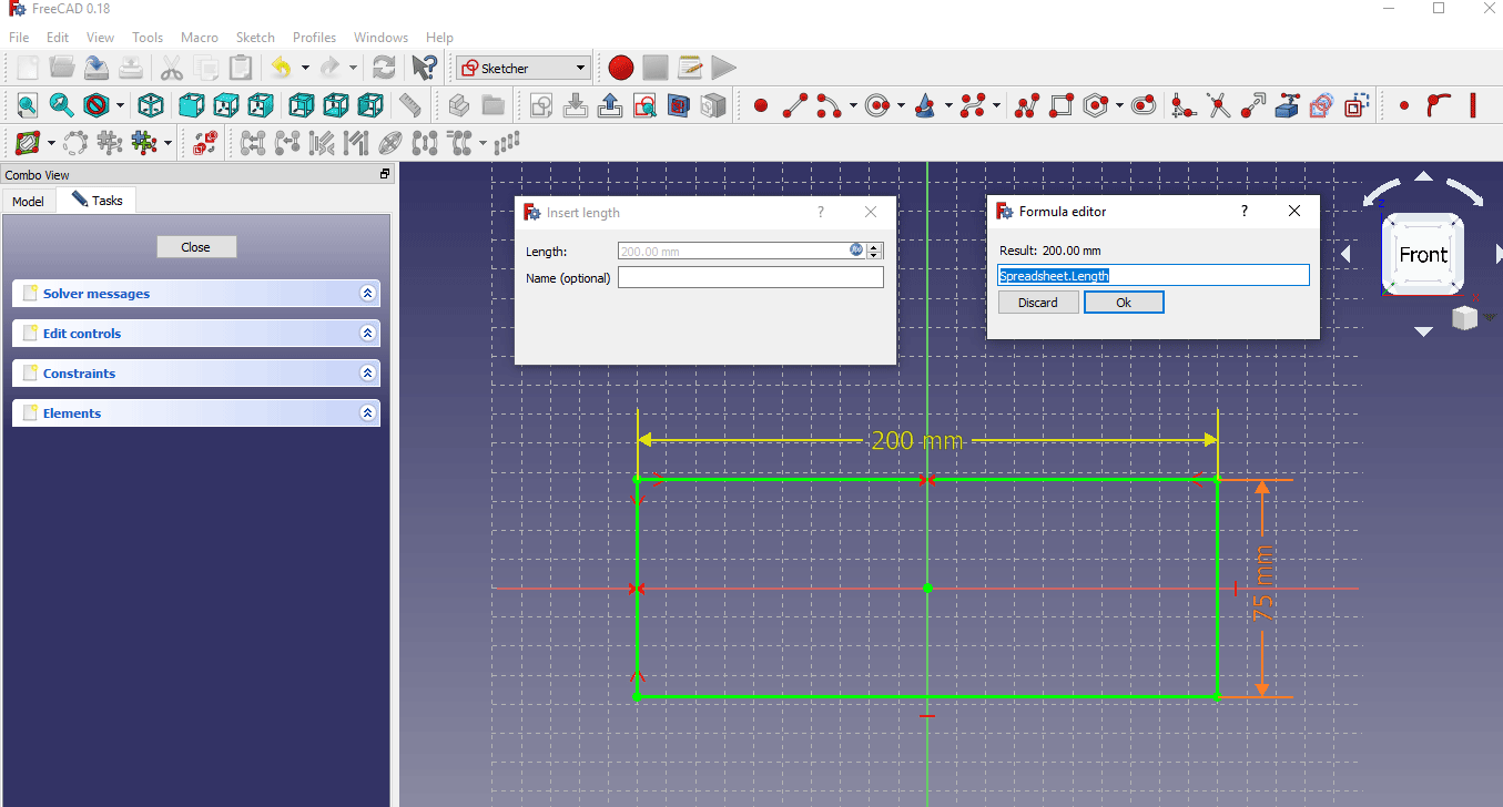
1. To add the measurements to an image, it is only necessary (open the created
sketch, double-click on it) assign the dimension in the indicated place by
double-clicking on the value to modify this data.
2. Click on the icon located next to the value on the right side.
3. Write the name of the parametric sheet followed by the name of the variable that is required, this is repeated for each measurement you decide will be parametric.
-
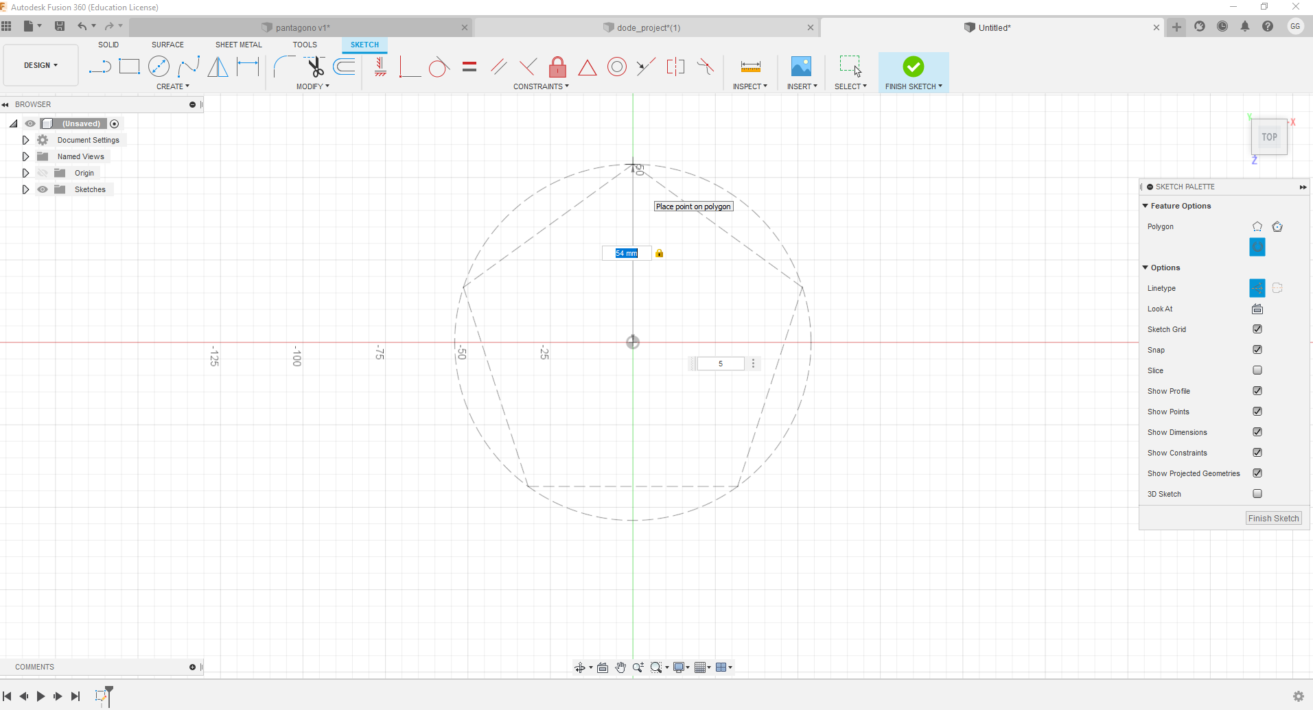
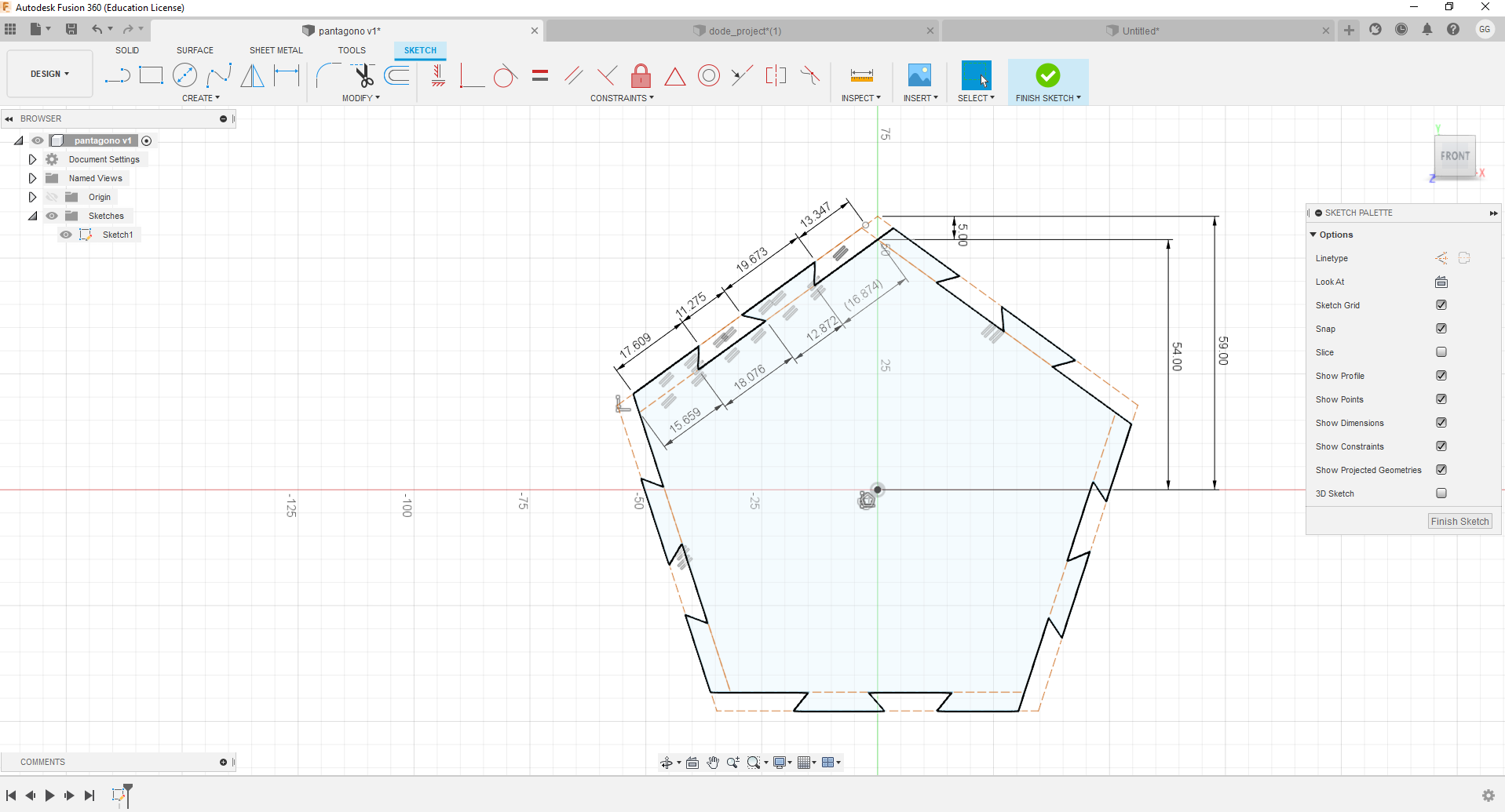
Create a new project, add a sketch at x, y coordinates, and create a polygon.
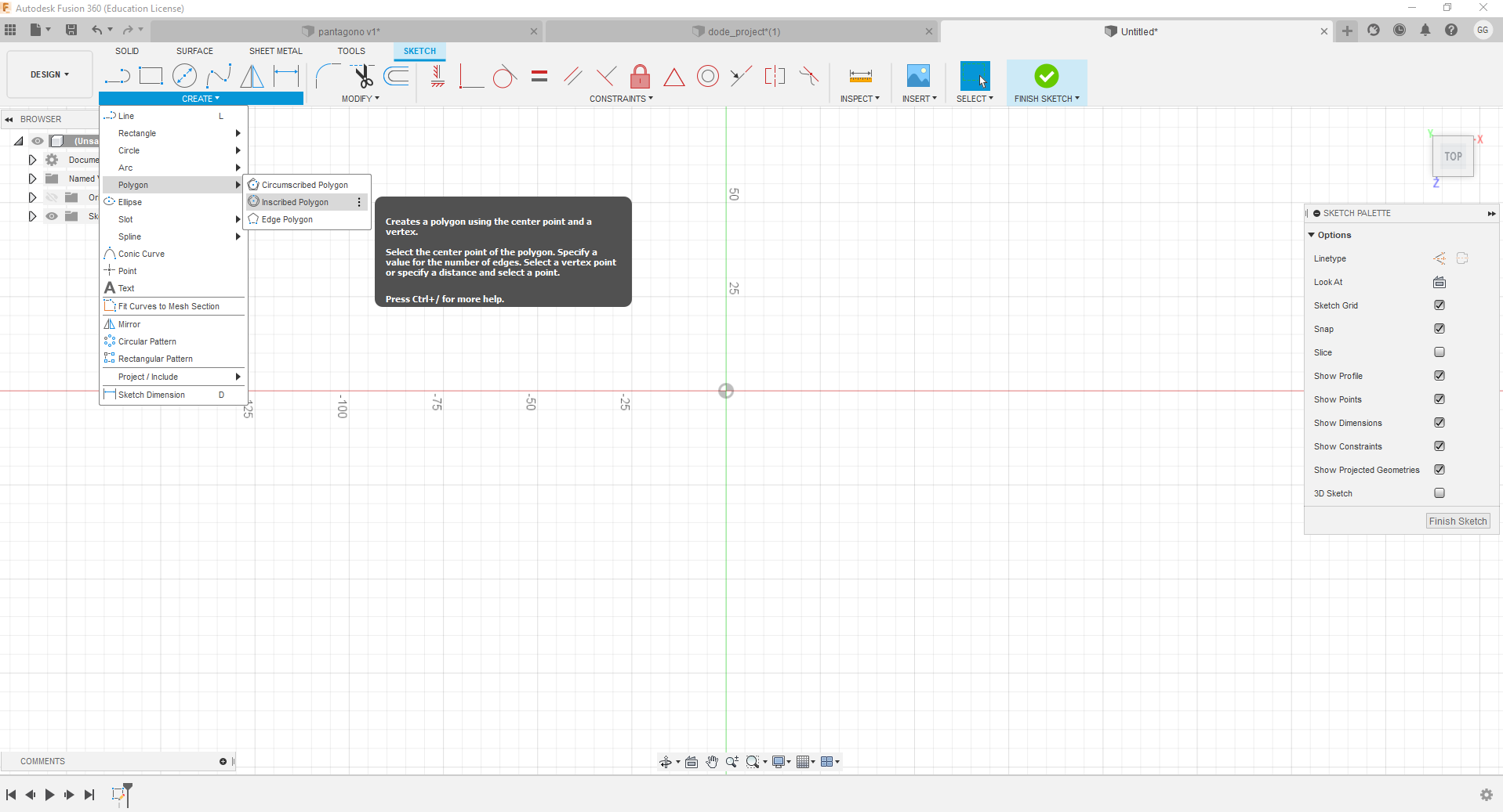
-
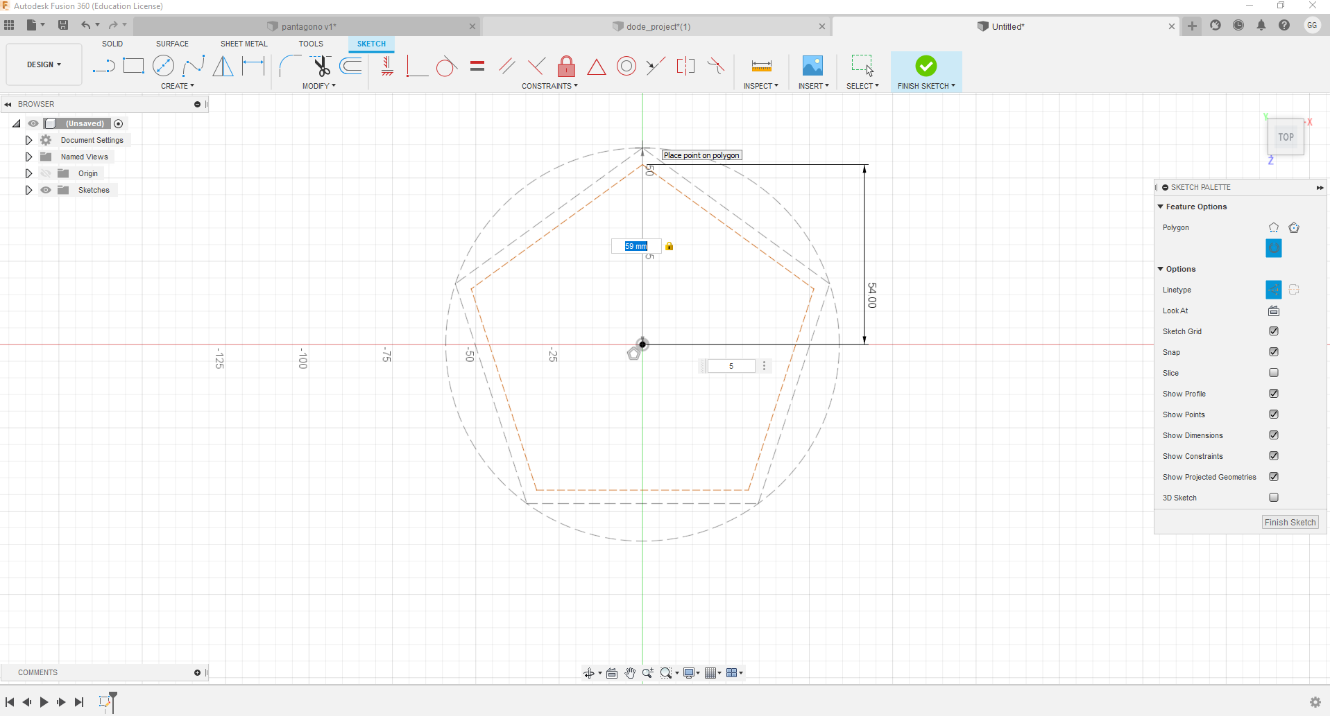
It must be an inscribed construction polygon, measuring 54mm and 5 sides.
-
Another 5-sided 59mm radius construction polygon is added.
-
Create construction line.
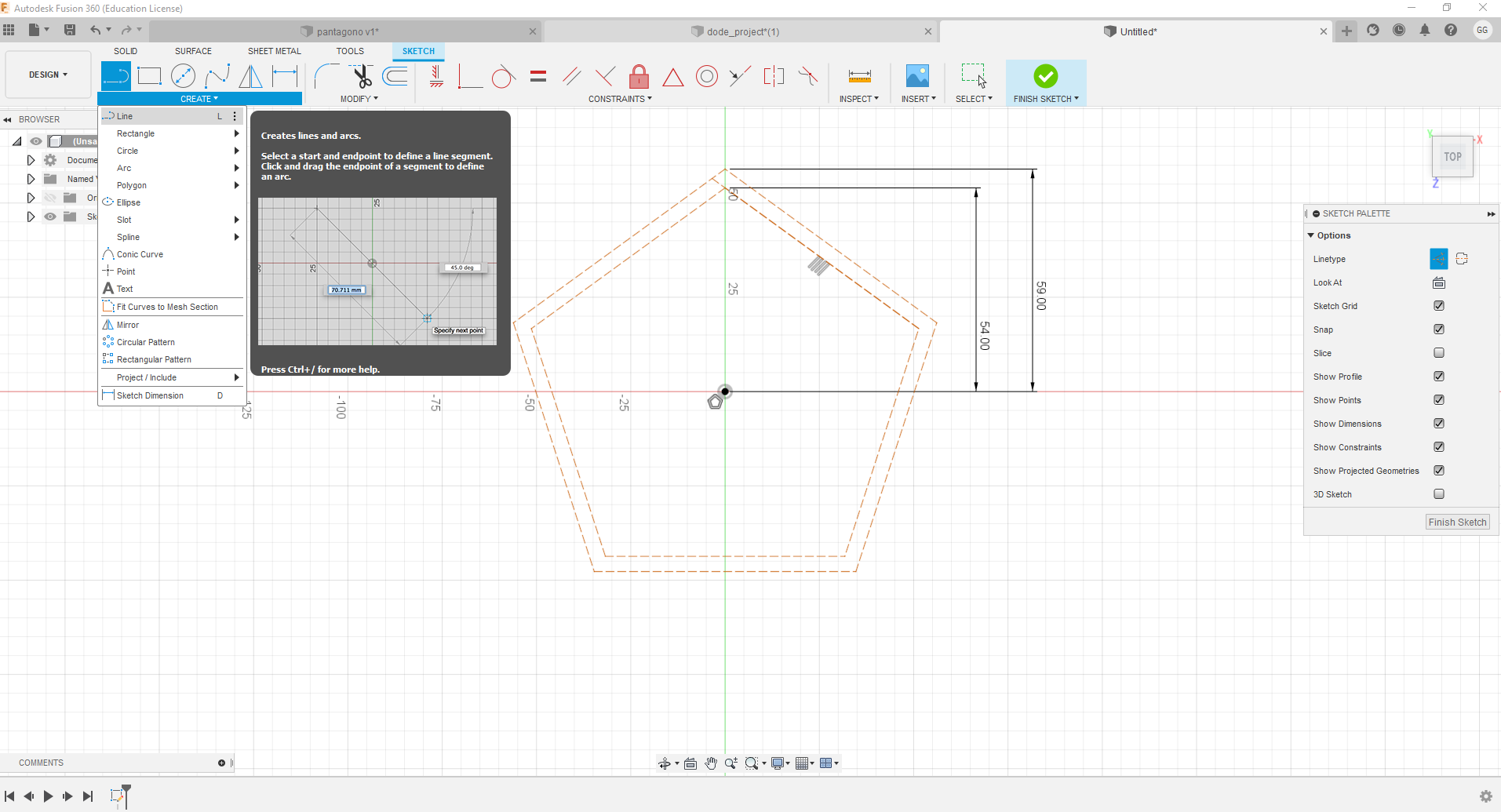
-
Create another construction line.
-
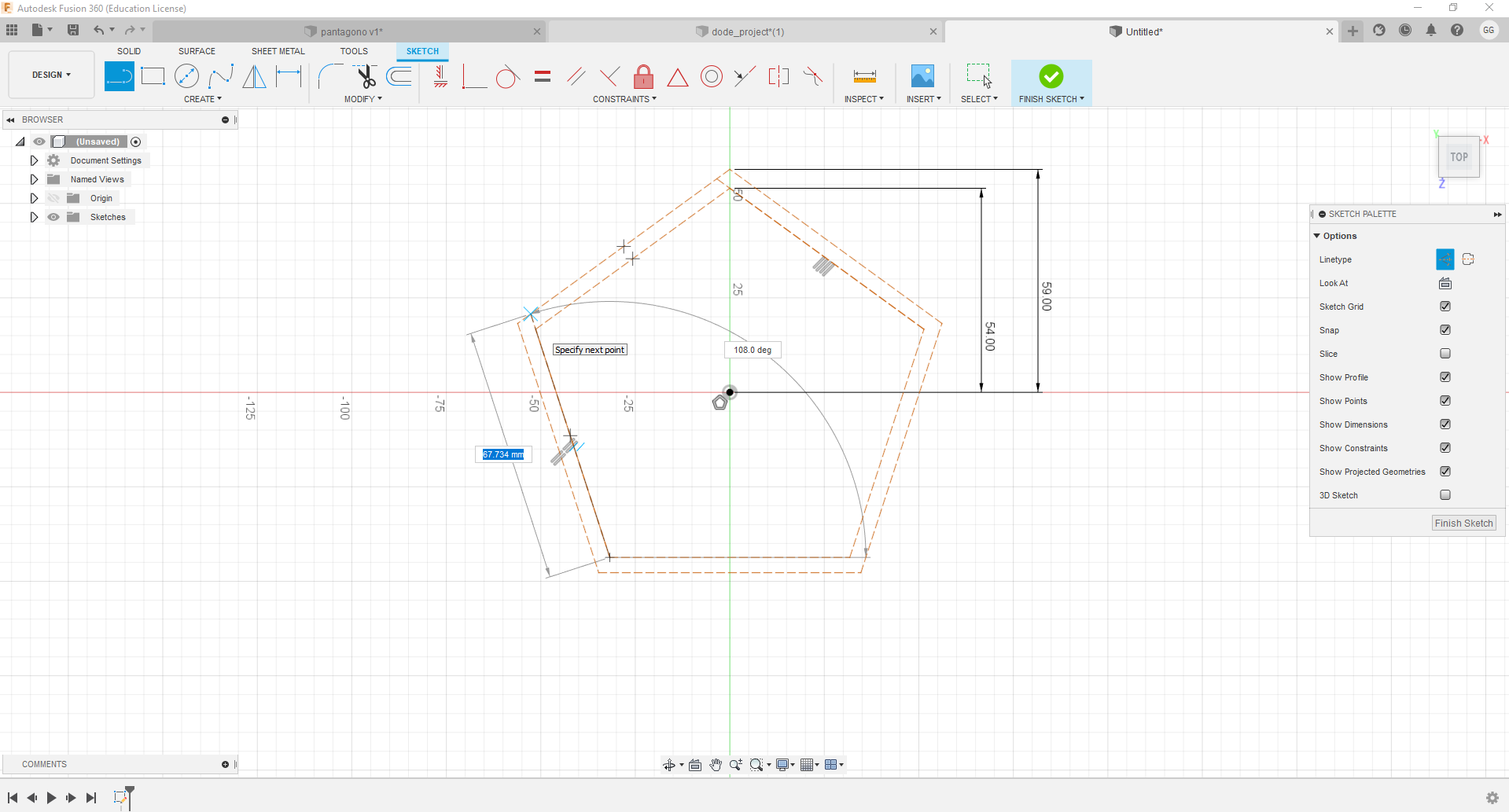
Using the create line tool, each one is created, with the values shown, those that
appear with a broken line are for construction and serve as a reference to draw the
shape. In the case of those lines that have no measure, they are only drawn between
the respective points of each level.
-
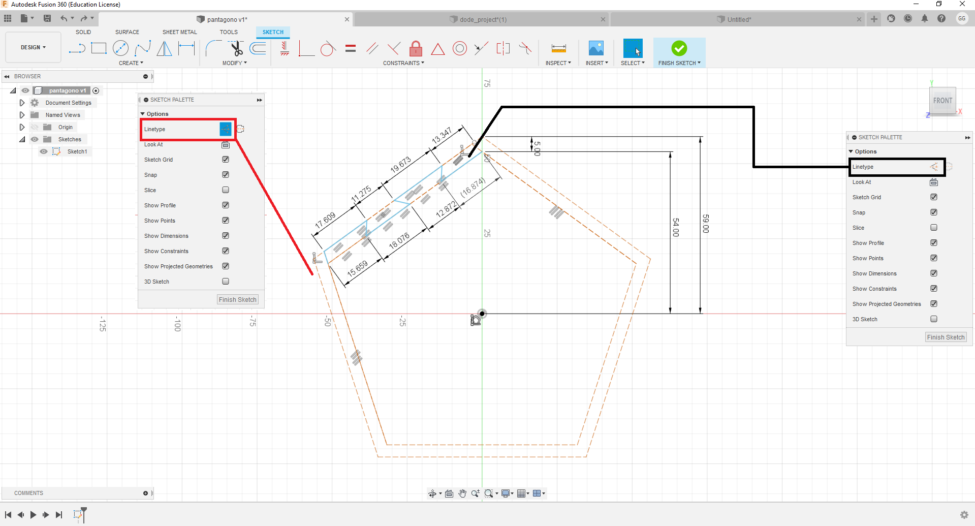
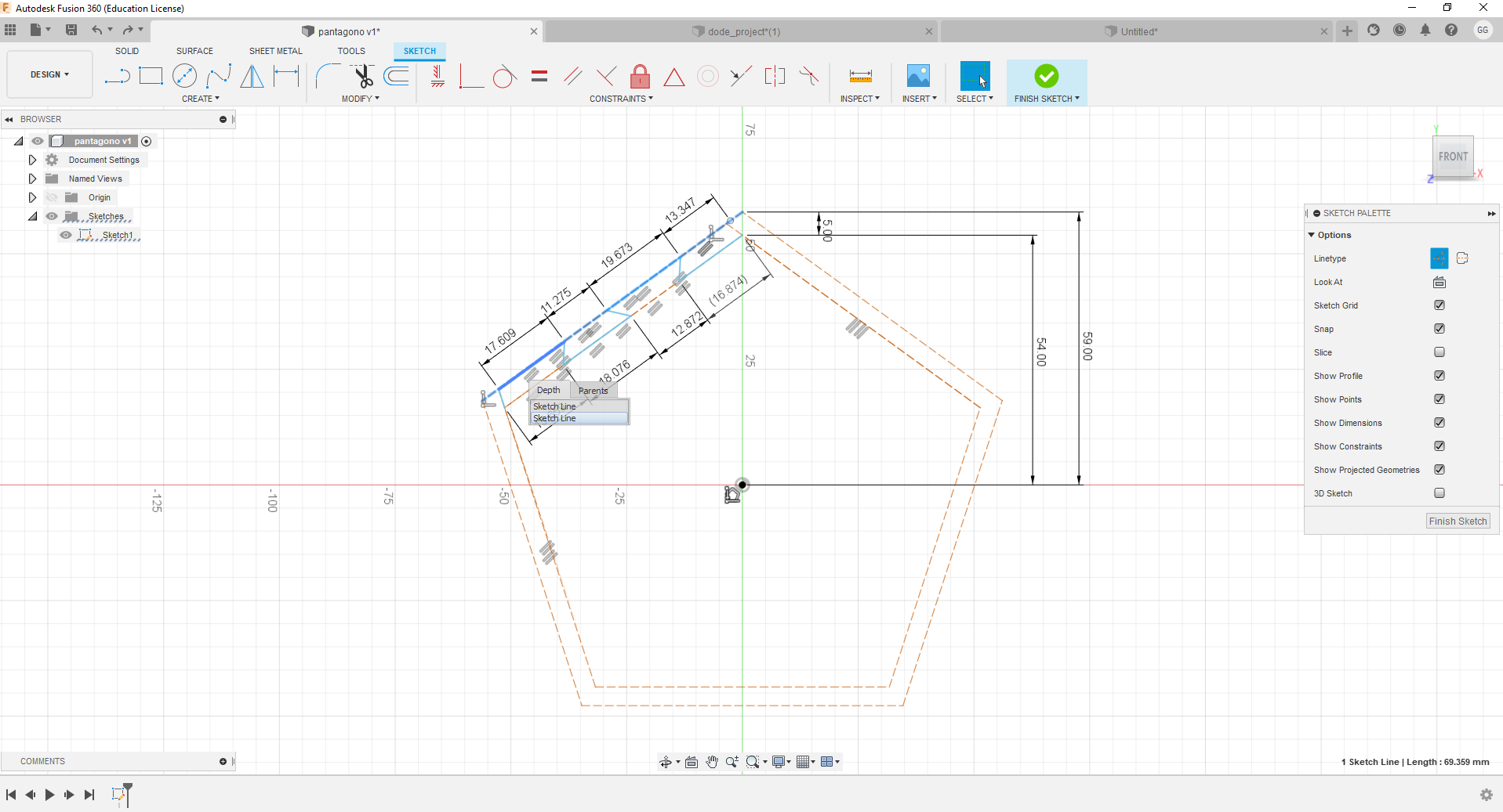
To apply fillet, select the corner lines and apply the fillet parameter.
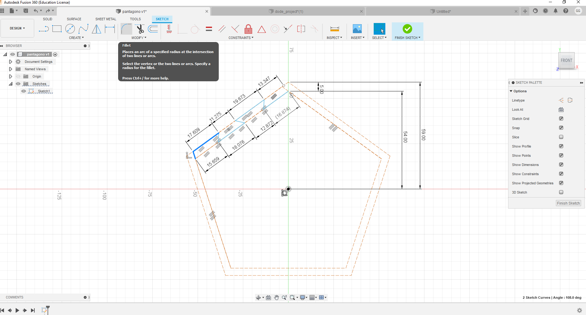
-
If when selecting the line, the entire selected line appears, left click without
releasing until the menu that allows you to choose the desired line appears.
-
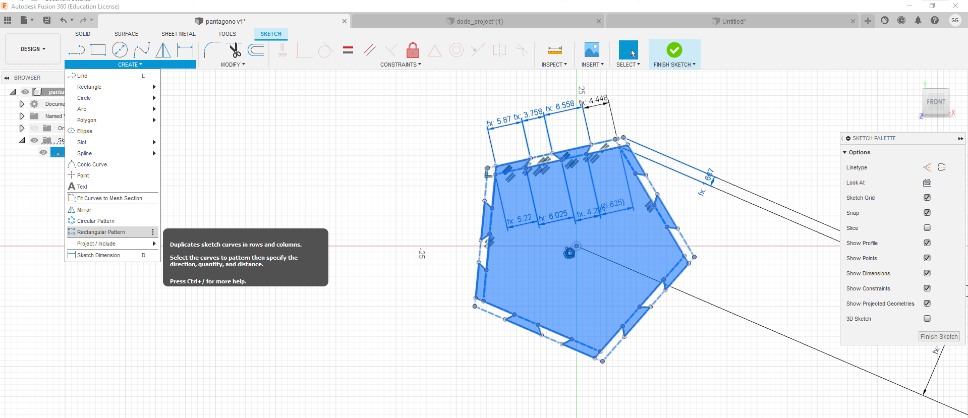
To apply the design created on one of the sides of the polygon, you must select each
of the lines and create a circular pattern.
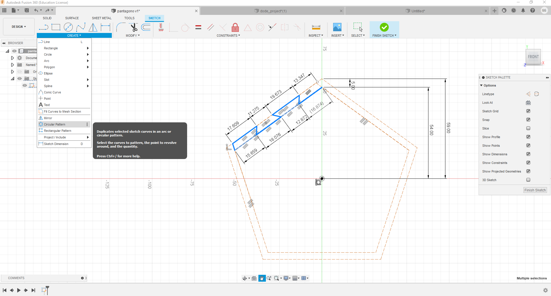
-
Click on select, then on the center of the pentagon and type 5.
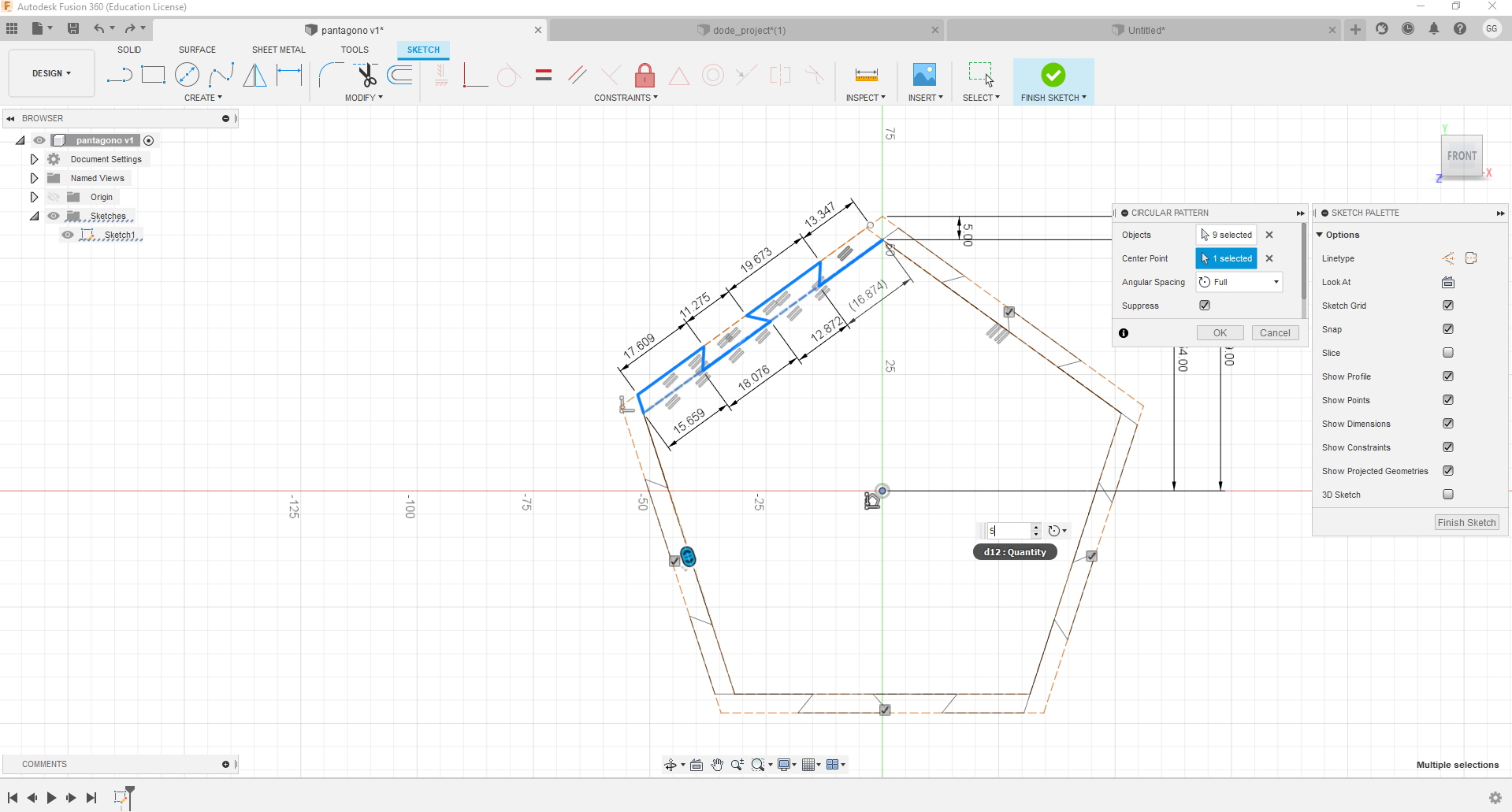
-
Press the enter key and you're done.
-
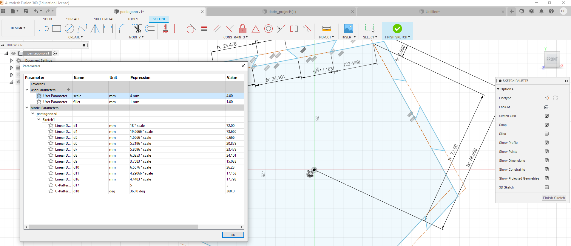
To apply the parametric design, select in the menu modify change parameters.
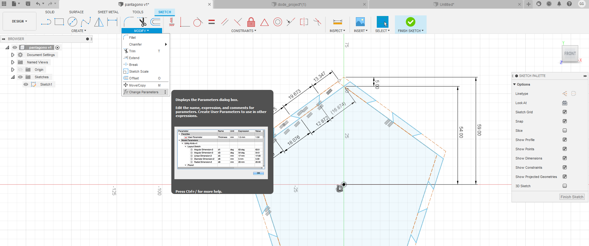
-
Change the value of the expression of each parameter by dividing the value by 3 and
multiplying the result by scale.
In this example it is done to start from the smallest measurements and to be able to
scale the size 1 by 1 to carry out the tests.
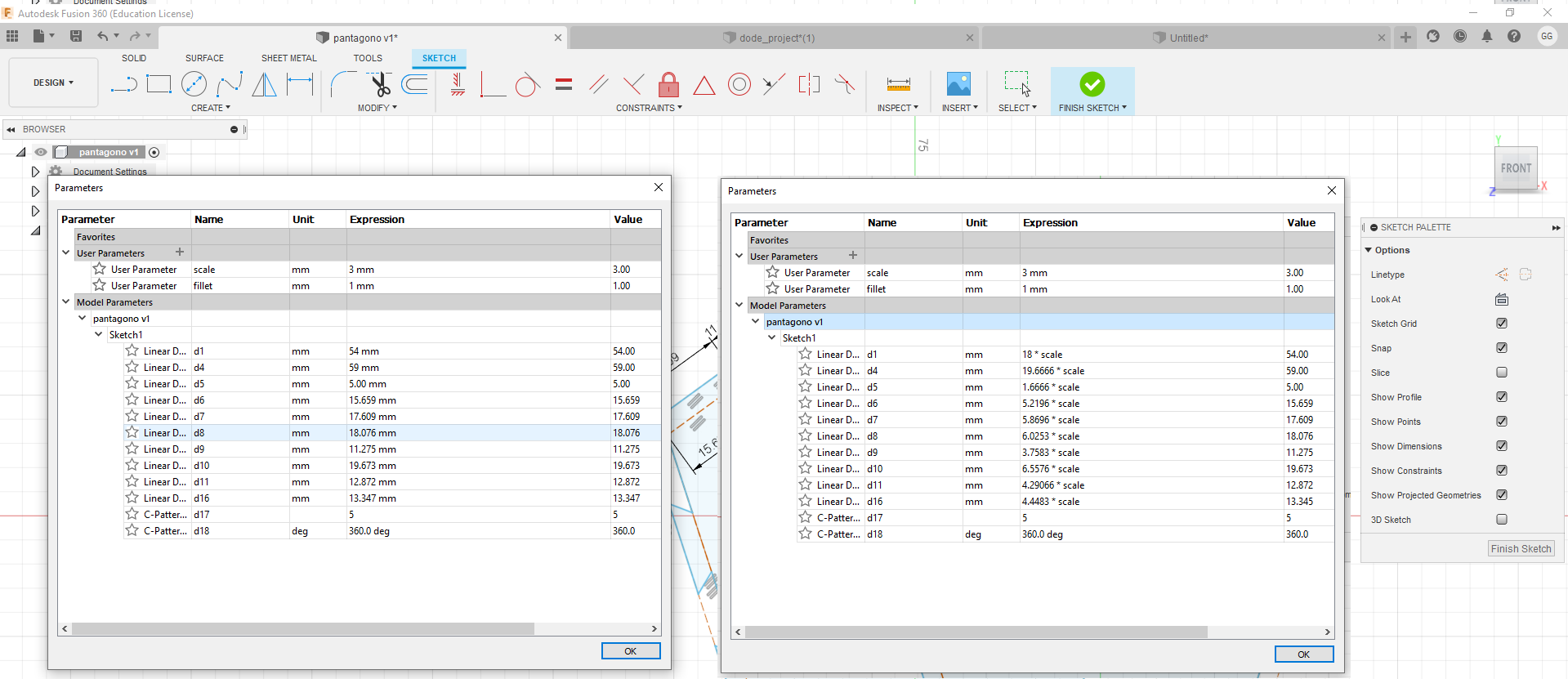
-
When you change the scale value, the image is resized.
-
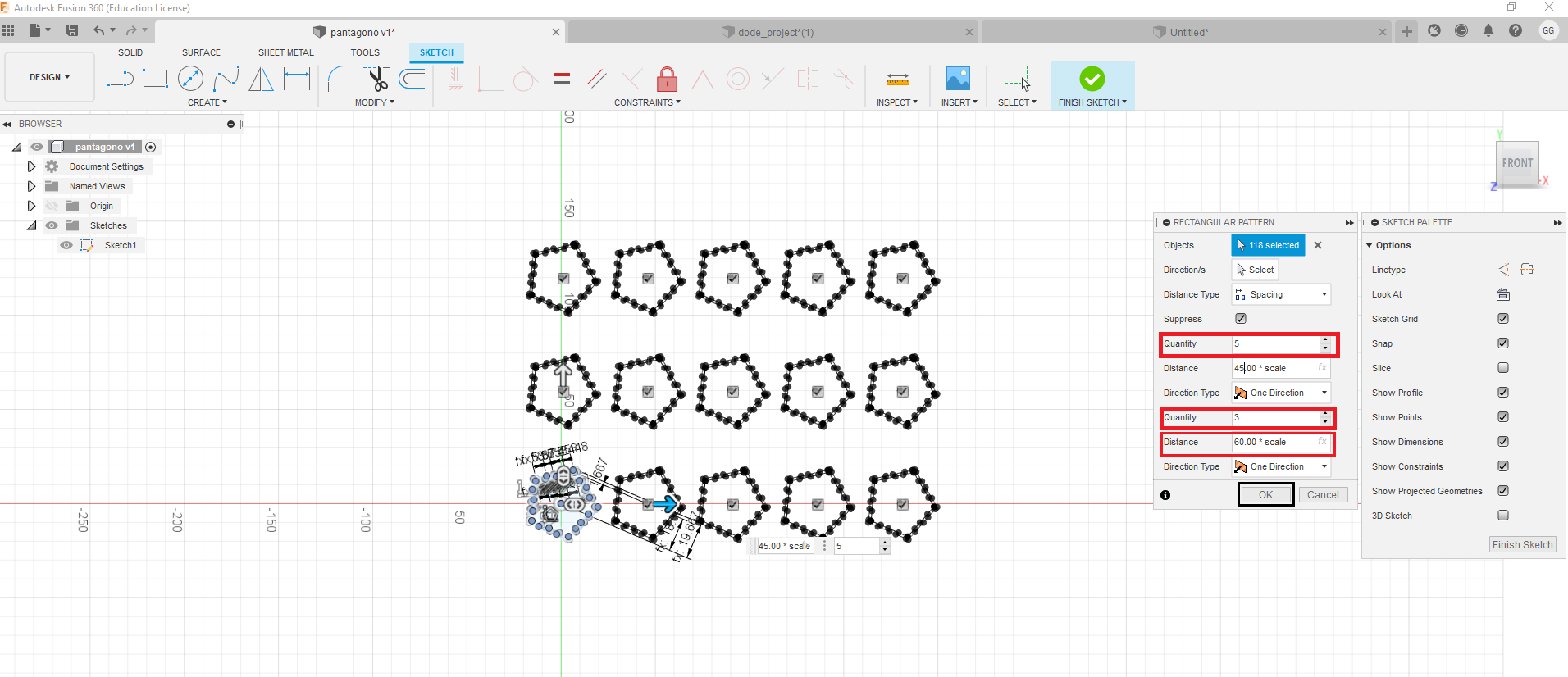
To repeat the rows and columns, use the rectangular pattern tool, you need to select
the entire figure.
-
The quality and distance are established using the scale parameter, so a 5x3 matrix
is created.
To finish the sketch must be finished.
- Lasercut 5.3 – Control Software. This is used to prepare the cutting files before sending them to the laser
- Driver – Softdog USB Dongle. An additional driver for the USB dongle if you are using a 64 bit version of Windows 7
- Driver – Laser Cutter. The driver to connect directly to the laser cutter.
After reading information about parametric design, I managed to do my homework, I first
experimented with freecad, it is not complicated to use the parametric, how complex it
is
for me to integrate several designs, I thought about making a cube and creating 4 files
one
per face.
parametric construction kit
I remembered about a toy called "Tazo" that came in a food product called "Sabritas", specifically this edition of the "Tazo" was made to form a dodecahedron trying to mimic a soccer ball. So I decided to recreate it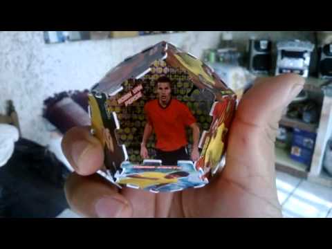
is time to prepare the laser cutter.
The Lasercut 5.3 installation files can be downloaded here. Extract the files from the zipped
archive to a new directory.
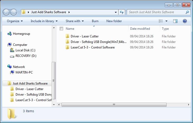
The archive contains 3 folders,
In a typical install all the required drivers will be set up as part of the Lasercut Installer, the additional drivers are only provided for completeness. Installing Lasercut 5.3 on Windows 10 Your laser cutter driver file will not install on Windows 10 as it is designated unsigned by Microsoft. On previous distributions of Windows, a click-to-continue button allowed the installation of unsigned drivers. In Windows 10 you must enter a special mode similar to safe-mode in older Windows distributions. To enter this mode requires a shutdown/restart of your computer. Make sure you have closed and saved any work or applications before restarting your computer. You must be an administrator user to complete this installation.
Click the Windows icon (usually at the bottom left of your screen), click on POWER, then click on RESTART whilst holding down the SHIFT key.
This will restart your computer and may take a few minutes. It will load the following screen:
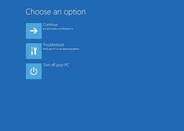
Click on TROUBLESHOOT.
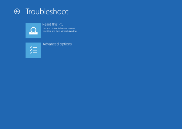
Click on ADVANCED OPTIONS.
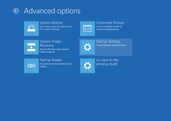
Then click on STARTUP SETTINGS.
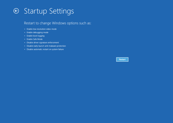
The STARTUP SETTINGS screen shows you the options you will be allowed to change once you have clicked on RESTART. This will again, reboot your computer to the following screen.
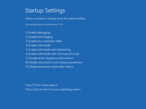
Now using the keyboard press F7. This will "DISABLE DRIVER SIGNATURE ENFORCEMENT" and allow us to install the unsigned laser cutter driver. Pressing F7 will reboot your computer to the usual Windows login screen. This may take a few minutes.
Once you have disabled driver signature enforcement installation is the same as for Windows 7. Instructions for which can be found here
I could not do the laser cutting practice, because I did not have access to the required machinery and therefore I do not know if my designs work and I have not had the pleasure of trying my first designs, but as soon as I can go to the node of Yucatan I will know how to operate these equipment.
Before uploading the file to the laser cutter software, I decided to use the Aspire free
trial. The trial software has no time limit or requires you to register with your personal
details. All features are enabled and there is a selection of free projects available to
download and cut on your CNC machine or laser cutter to verify compatibility.
The intention is to verify some datelle regarding the design and dimensions of the design
before laser cutting.
As you can see in the image, you can set the dimensions, the thickness of the material (mdf,
vinyl, etc.)
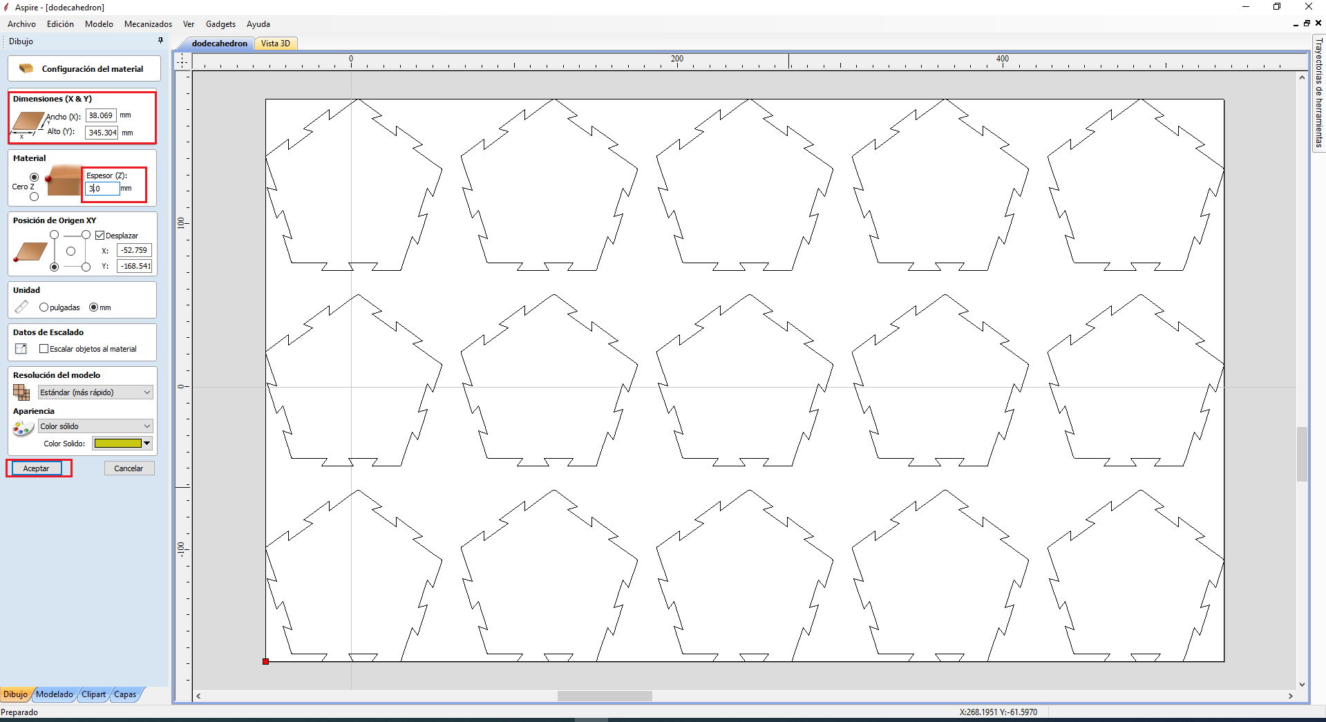
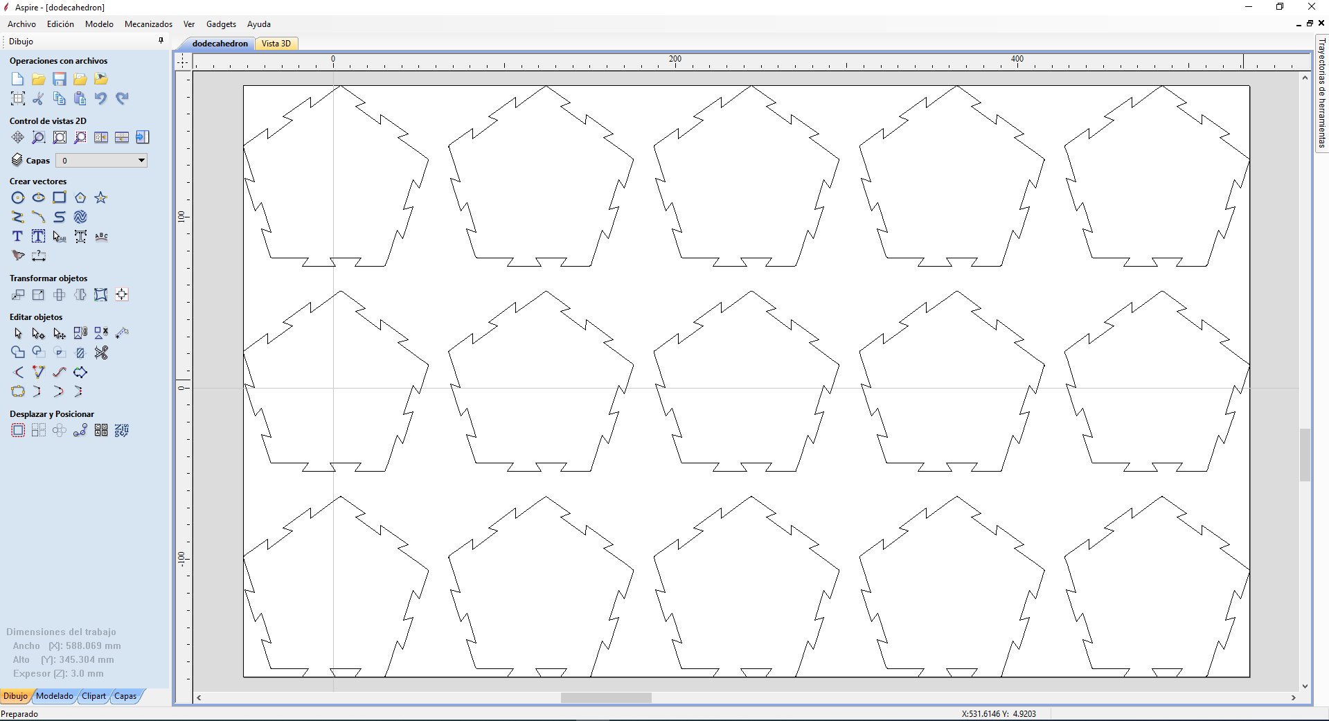
When you click the ok button, it shows the layout and the left lasso has a series of tools
that allow you to make adjustments, such as transforming or editing objects.
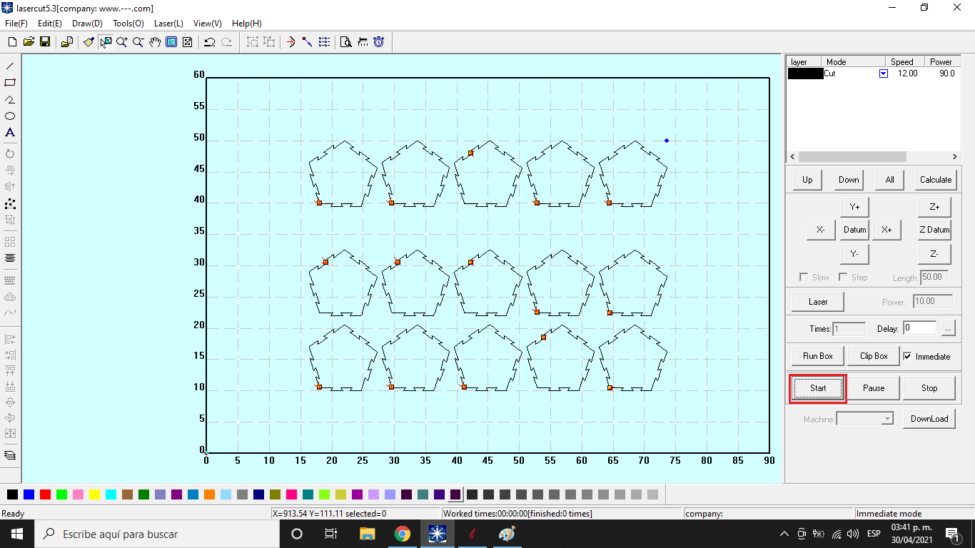
The file is now loaded into the laser cutter software. In this stage the speed and power of
the laser is established, in addition to establishing the values of the coordinates, as well
as choosing the machine to use, in the same way it is established if it is cut or engraved.

Once all the parameters have been established, click on the start button, remember that you
must verify that the cutter is connected to the computer.
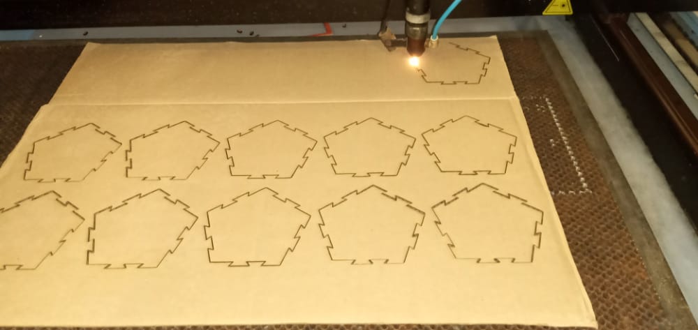
Cardboard is used to make the cut, due to its flexibility it will give the shape of the
design.
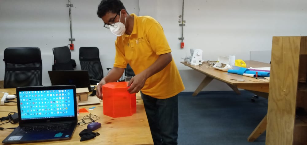
Finally the piece is assembled.
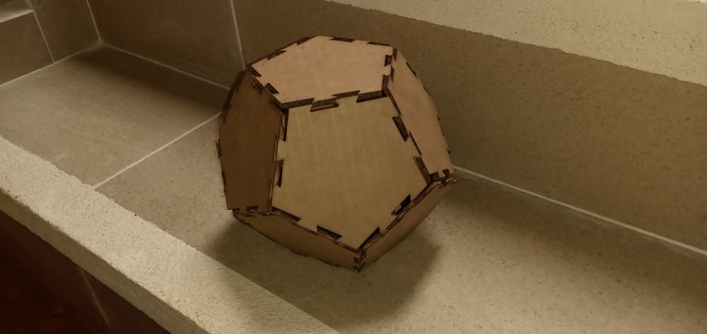
The sides that make up the body, horizontally assembled precisely, however because these
sides meet at different angles, it is somewhat complicated to join the parts.
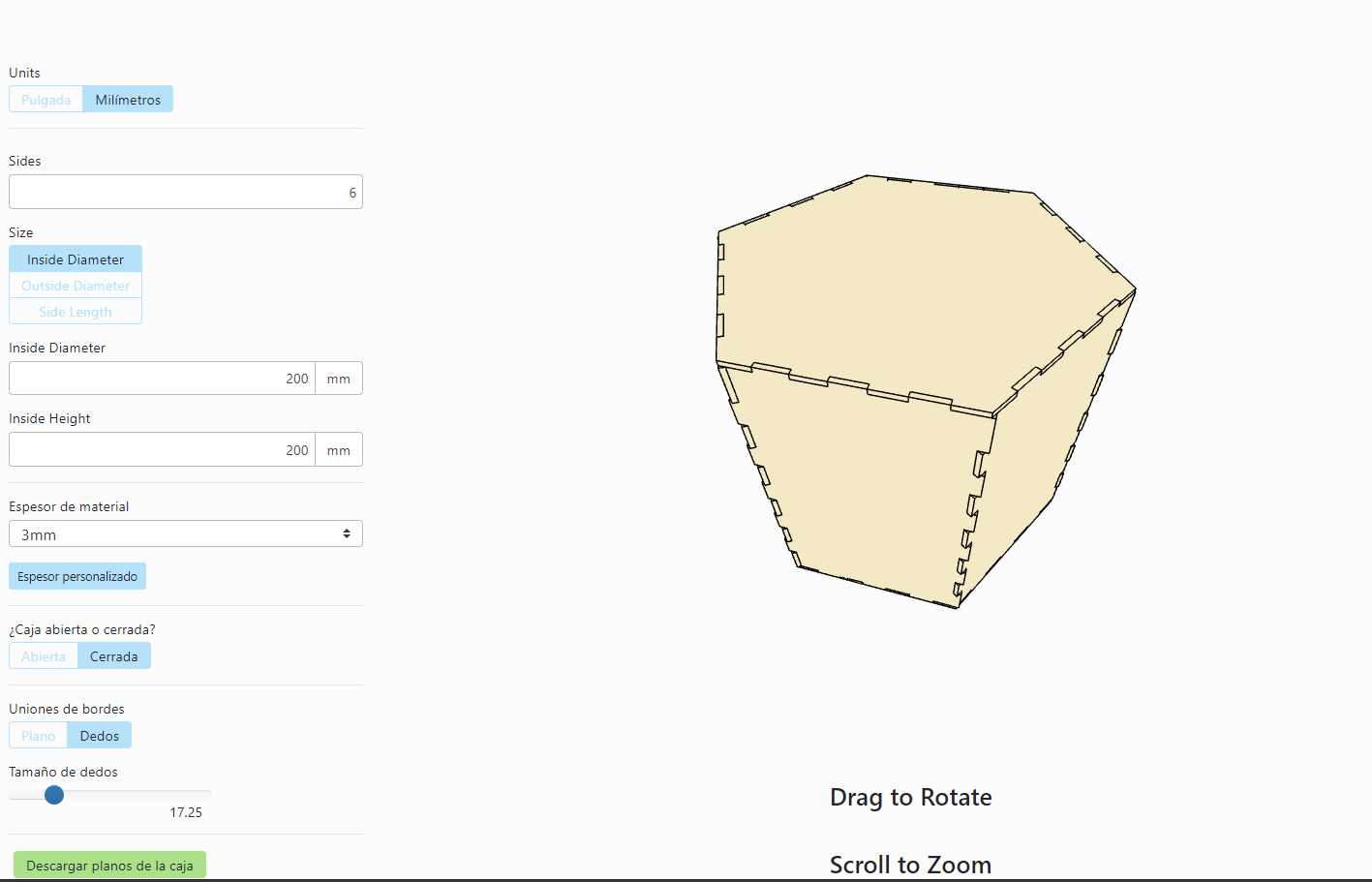
To create designs for cutting there is a website which allows you to
choose between basic box, polygon box, notched bent box.
To create designs for cutting there is a website https://www.makercase.com/#/, which allows
you to choose between basic box, polygon box, notched bent box. To test I used the polygon
box option giving the values of 200x200mm.
As the intention of this test is to do laser cutting and engraving, I am going to modify the
dxf file in aspire (using earlier this week), because I include a flower, a butterfly and
three leaves. To add the design for the engraving, select import from the file menu,
preferably a vectorized image.
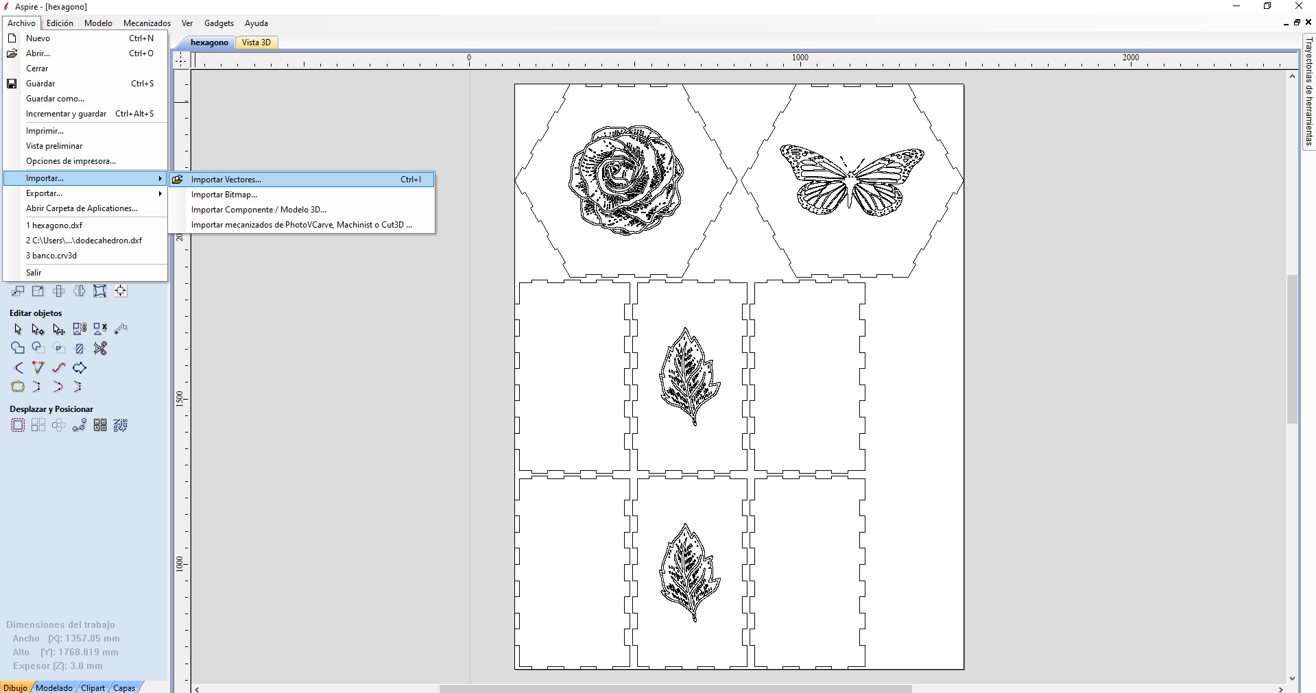
Now you have to export the file to dxf.
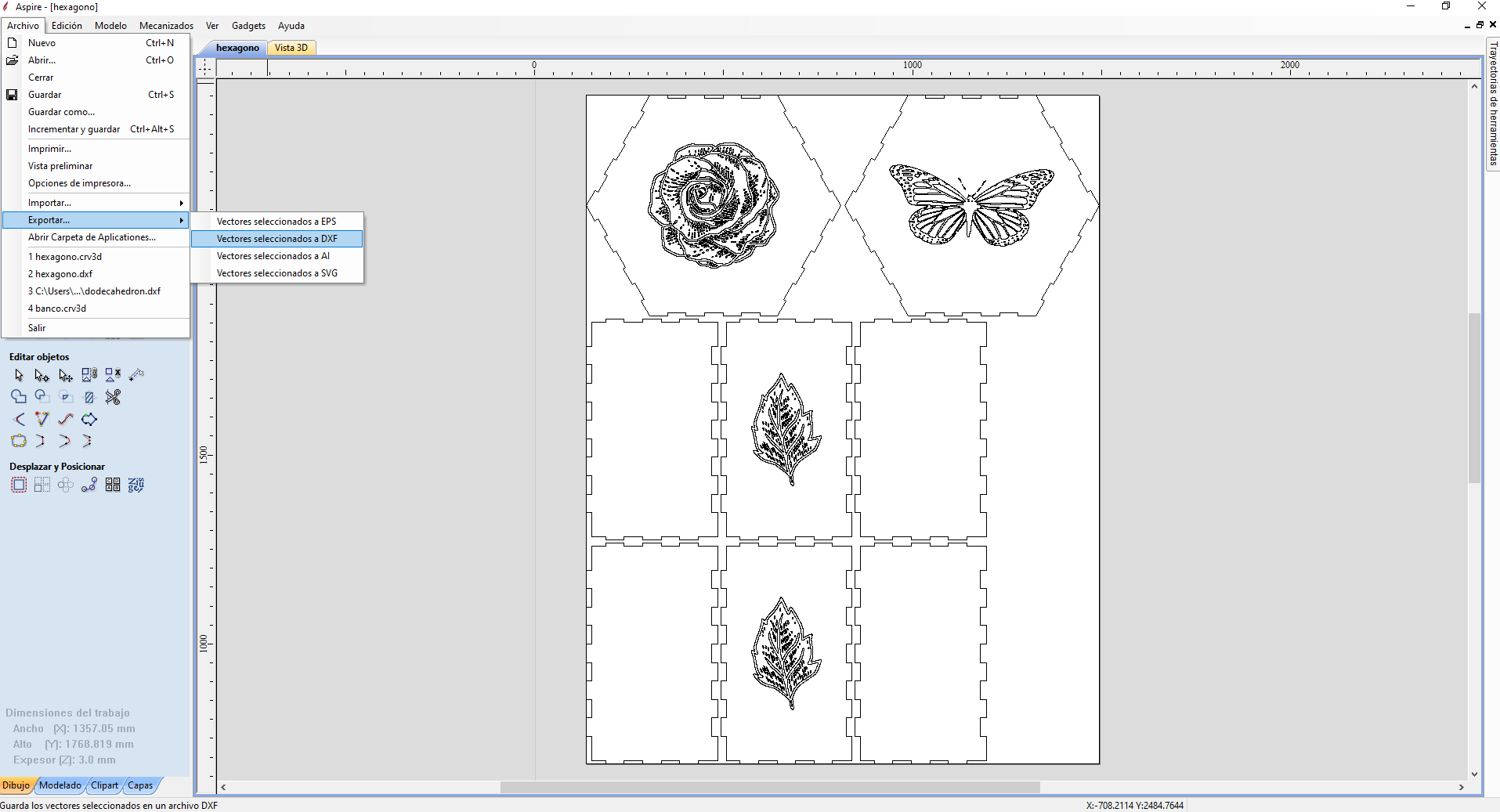
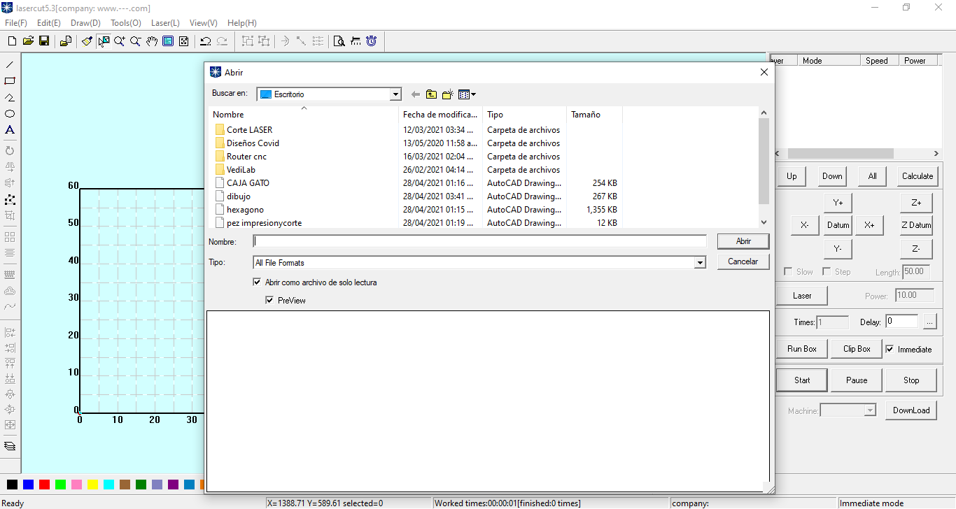
Preparing the file for cutting, import the file created in the previous step into the cutter
software (lasercut 5.3).
Due to the position of the image, it is rotated 90 degrees.
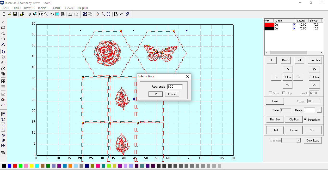
To avoid mistakes during the cutting and engraving process, the join lines tool is used.
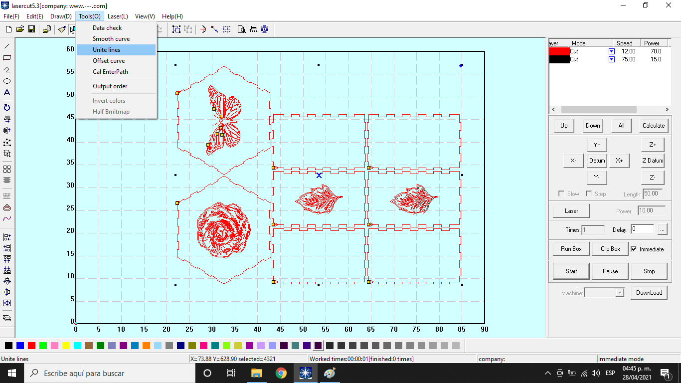
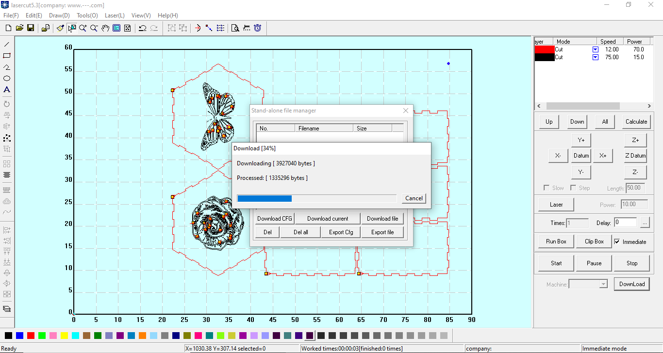
The download button is used to upload the design to the cutter.
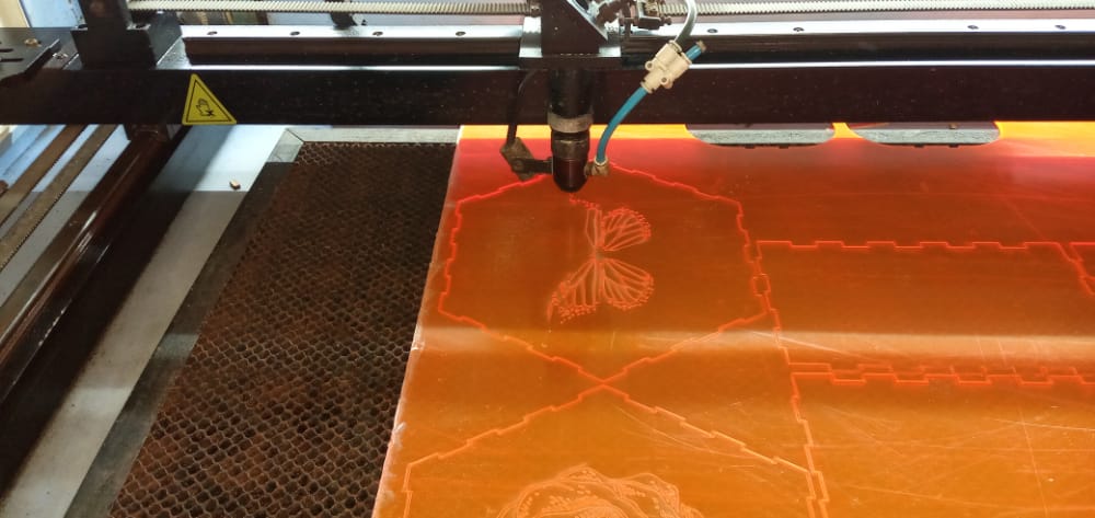
The laser cutter is now doing its job..
It is the long-awaited moment to assemble each of the parts of the object
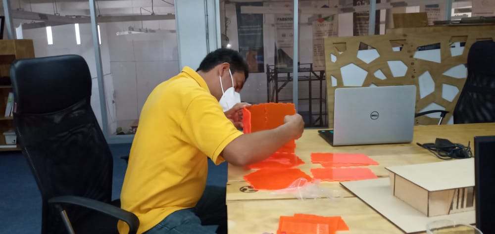
Finally each of the parts were integrated to form a body, the only detail is that each part
does not stop by itself, for this work plastic material was used.
Tolerance can also be set prior to cutting. In general, I like how the part was assembled, I
am excited because after many months of waiting I was able to do the practice.