Introduction.
I think this week's theme is the central point for all the work that will be done throughout
the course, computer-aided design opens up many possibilities to shape those ideas that
sometimes occur to us.
In week two, a review was made of a wide variety of software that exists for computer-aided
design, both for 2d and 3d image design. It is advisable to use as many programs as possible
and know the advantages and disadvantages.
2d design software.
The two-dimensional adjective is used to refer to images that have two dimensions (2D). It is an image that is projected long and wide.
GIMP
It is a multiplatform image editor available for GNU / Linux, OS X, Windows and other
operating systems. It is free software.
GIMP provides you with tools for designing and editing images, allowing customization
and third-party add-ons.
A first difference of GIMP with respect to others
photographic treatment and retouching software is presented to the
check the non-existence of a unified interface for the
Program. GIMP does not have a graphic background on which
they open files and menus and, on the contrary, different windows
floats unfold directly on the desktop. East
It is a fact that can be disorienting at the beginning of using the
program but that ends up being easily integrated into a
work flow. Among the various pop-ups that
are displayed, the first to analyze and comment on is the
tools that contains an important list of the
themselves.
From this basic window the rest of the areas that
will allow the work of open images. Actually
a variable number of others can be displayed on the screen
windows, the amount varies depending on the needs of
The edition. Dialog boxes include those for
layers, channels or roads, or others such as those of
selection of colors, brushes, patterns, gradients and
paddles.
The toolbox, which appears when you open GIMP, consists of a window
that contains three menus (File, Extensions and Help) and icons that give access to
functions and work procedures. The icons in the middle of the box manage aspects
related to color and painting.
An area with the active tool options is displayed at the bottom of the box
which is updated based on it. In the example the active tool is the selection
rectangular
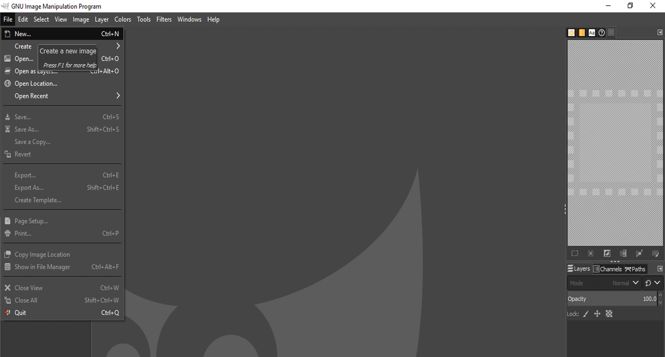
To learn the basics of how to draw lines, the first step is to open gimp, select the file
menu and choose new.
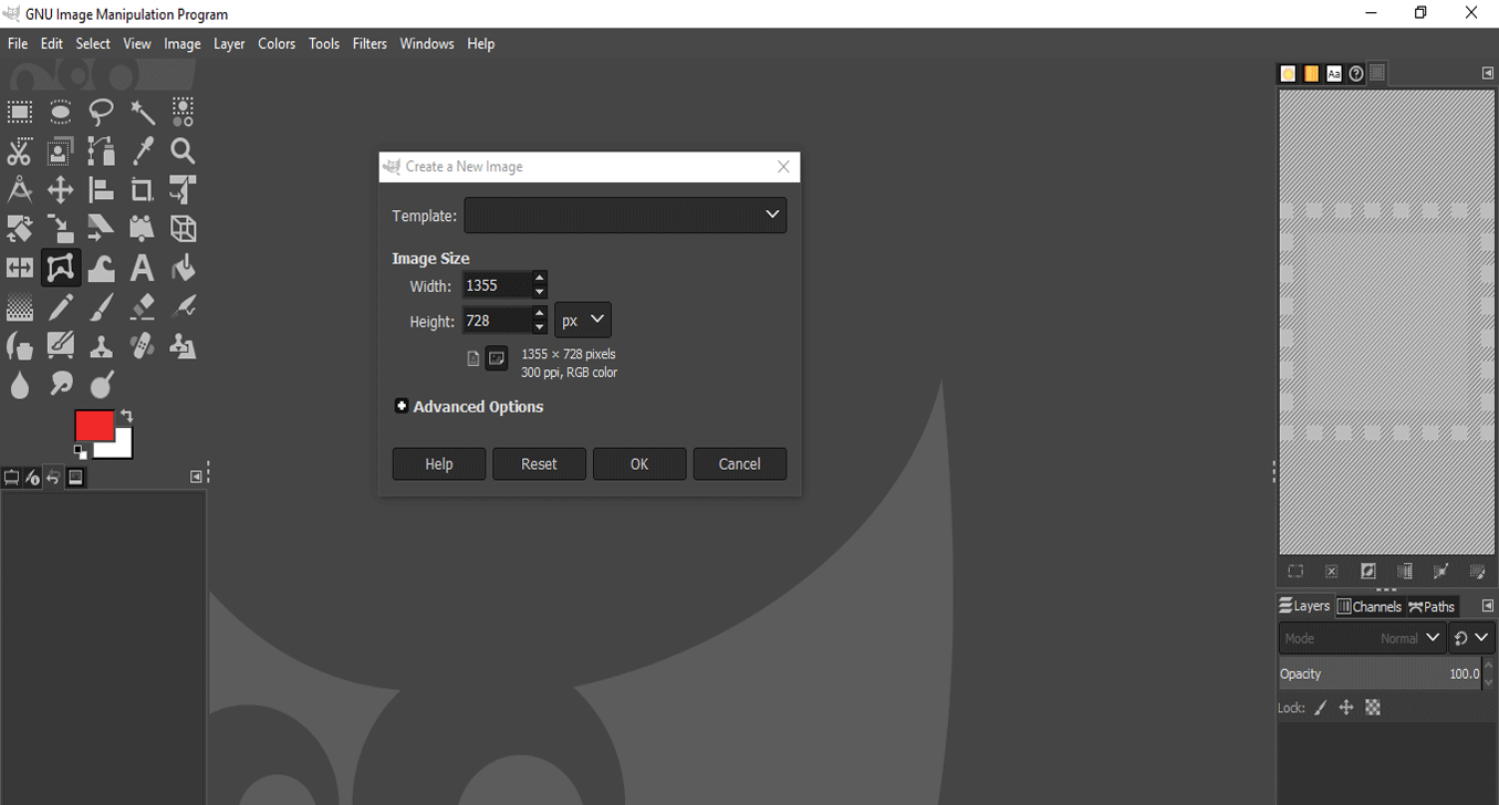
The next step is to define or set the size of the canvas, for this example it will be
1355x728 px, as you can see there is also the possibility of choosing a default size,
selecting it from the list (template).
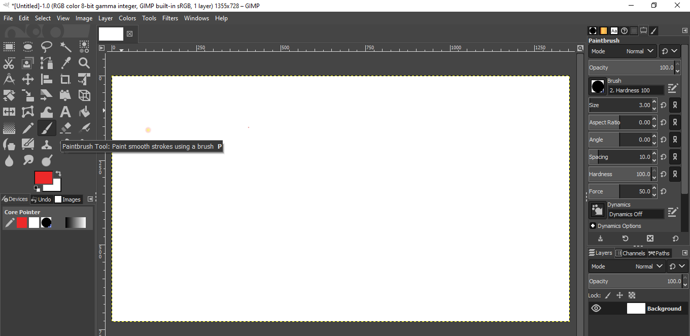
Click on the paintbrush in the toolbox. Click on the brush in the toolbox. To change the
size, double-click on it and the properties appear, we focus on changing the size, you just
have to write, increase or decrease the number, for this example, the size is 3.
Click in the image where you want a line to start or end. A single dot will appear on the
screen. The size of this dot represents the current brush size. Now, lets start drawing a
line. Hold down the Shift key, and keep it down.
After you have a starting point and while pressing the Shift key, you will see a
straight
line that follows the cursor. Press the first button on the mouse (the leftmost one usually)
and let it go. During that whole "clic" of the mouse button, you need to keep the Shift key
held down.
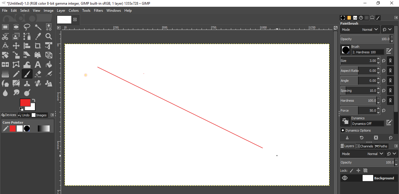
Now you have to draw another line, for this it is necessary to stand on one of the ends of
the previous line and click with the mouse, move the mouse without releasing the
Shift key,
once the second point is located, click and the line is trace between those points.
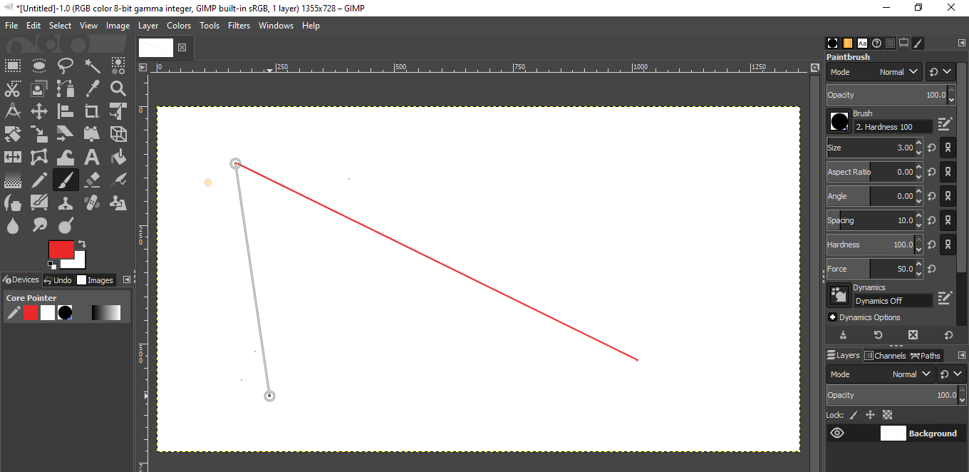
Finally another line is drawn to form a triangle.
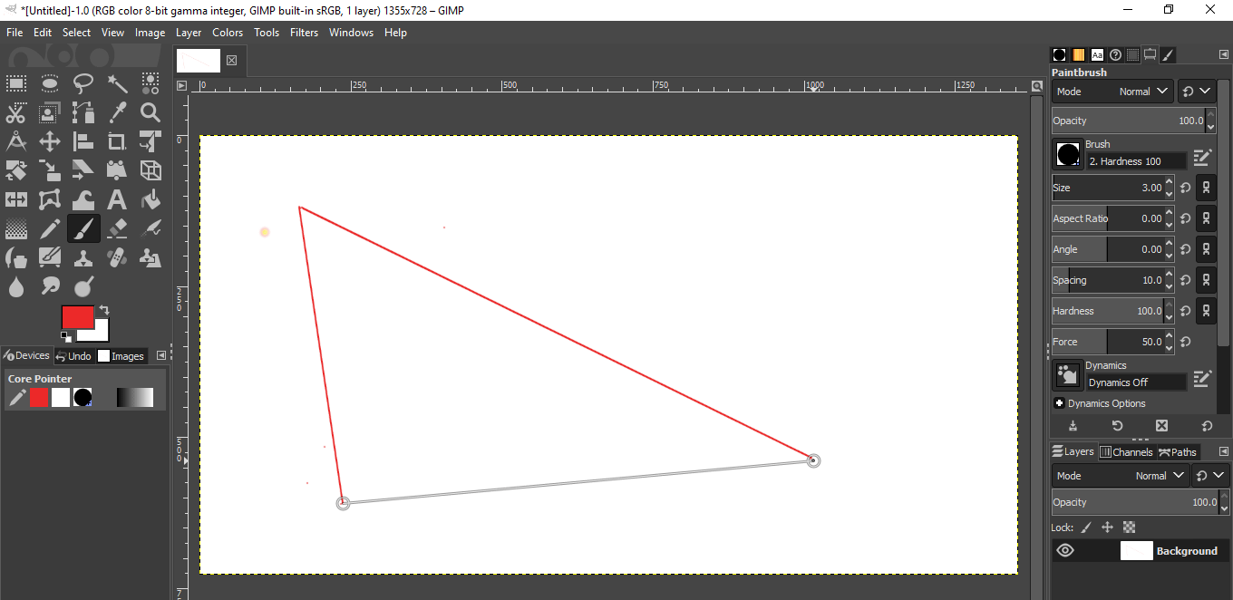
Now you have to save the file, to do this click on the File menu and select "Save".
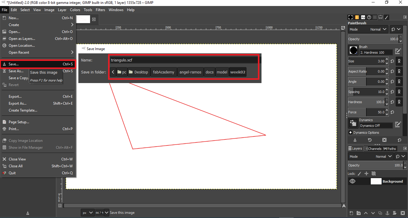
PHOTOSHOP
It is a raster graphics editor developed by Adobe Systems Incorporated. Mainly used for
retouching photographs and graphics. It has many tools that allow professional work.
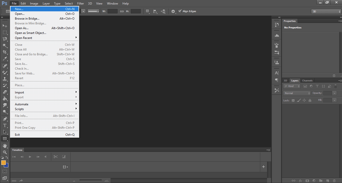
To create an image, the first step is to go to the file menu and select the new option.
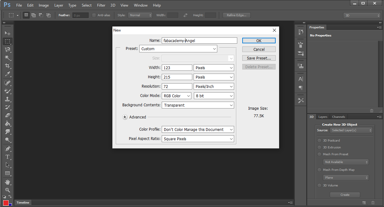
Then it shows a dialog box with the characteristics that the image will have, for this case,
I am going to create an image with transparency. The values shown can be modified according
to the required size of the image, for practical reasons I do not make any changes to the
dimensions.
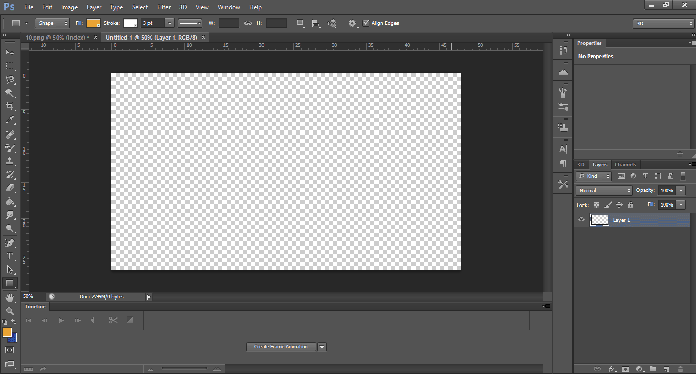
Clicking the ok button displays the canvas, to start creating the image.
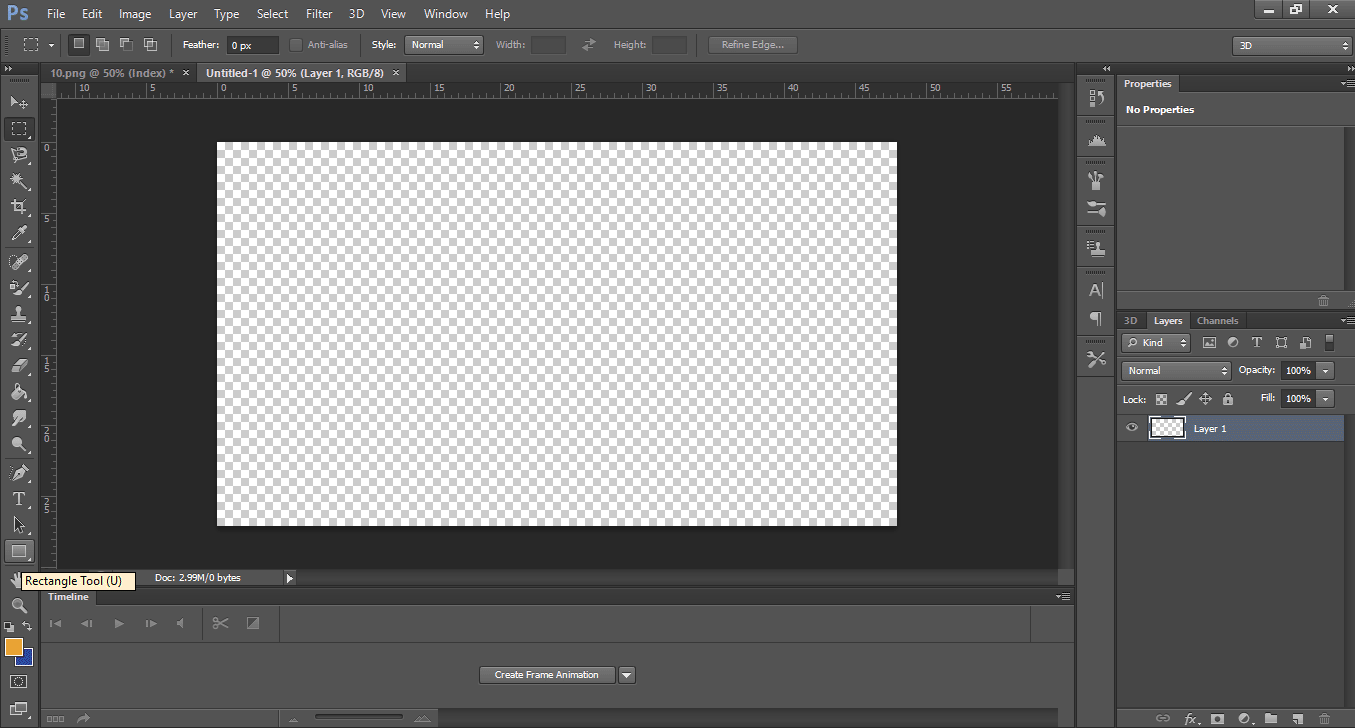
As an example, a rectangle is drawn, for which in the toolbox you have to click on the
rectangle icon, as shown in the image.
Now the mouse is positioned in the place that you want to start, for this you have to press
the left mouse button and release it once you have the required size.
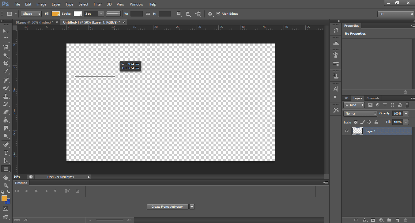
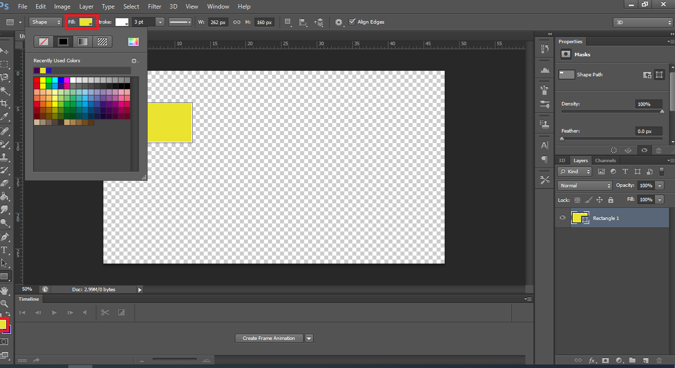
To change the fill color, just select the desired color.
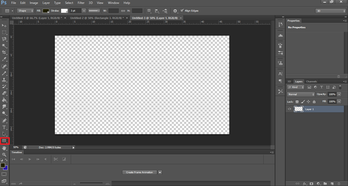
I am going to create a house, for this I use the rectangle tool. Remember to click on the file menu and then select new.
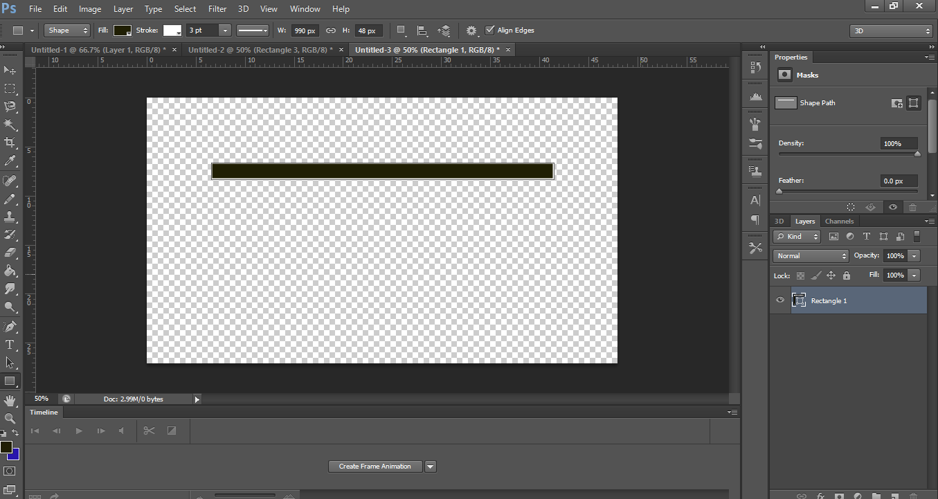
The first step will be to create a rectangle for the ceiling.
Again with the rectangle tool another image is created below the previous one (remember that you can change the color.
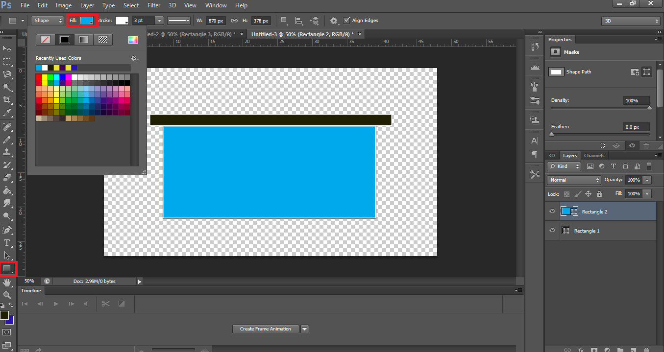
Now I draw the door using the rectangle tool again.
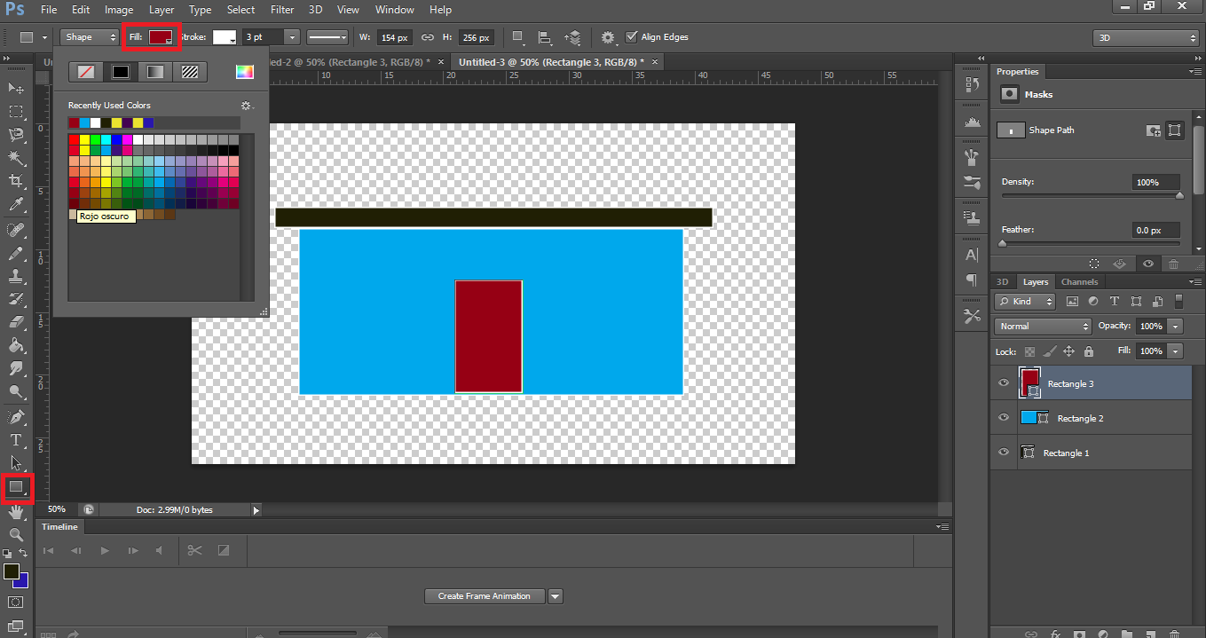
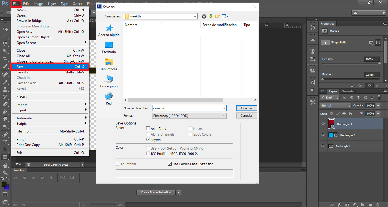
Once all the elements have been added to the design, it must be saved, to do this, click on the menu file and select Save.
3d design software
3D computer graphics, or three-dimensional computer graphics (in contrast to 2D computer graphics), are graphics that use a three-dimensional representation of geometric data (often Cartesian). In computer graphics software, 2D applications may use 3D techniques to achieve effects such as lighting, and, similarly, 3D may use some 2D rendering techniques.
- FreeCad
Is a software for open source parametric 3D modeling created primarily to design
any real-life objects of any size. The use of parametric modeling allows you to
easily modify your design.
-
I am going to create a design, for it in the menu file section new.

-
Now in the drop-down list select the option part design (workbench).

-
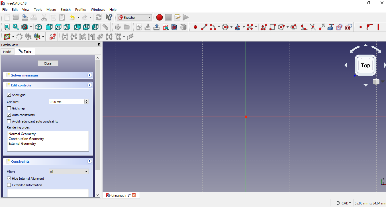
Then create a new sketch and select the xy plane.
-
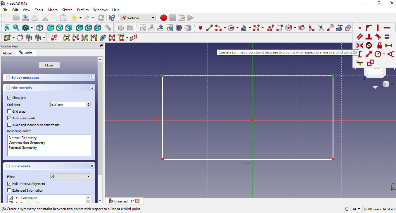
Create a rectangle in the sketch and apply symmetry, to do this select
with the mouse the start and end point of the horizontal line and then
select the vertical axis line and then select the create symmetry tool,
see the following image.
-
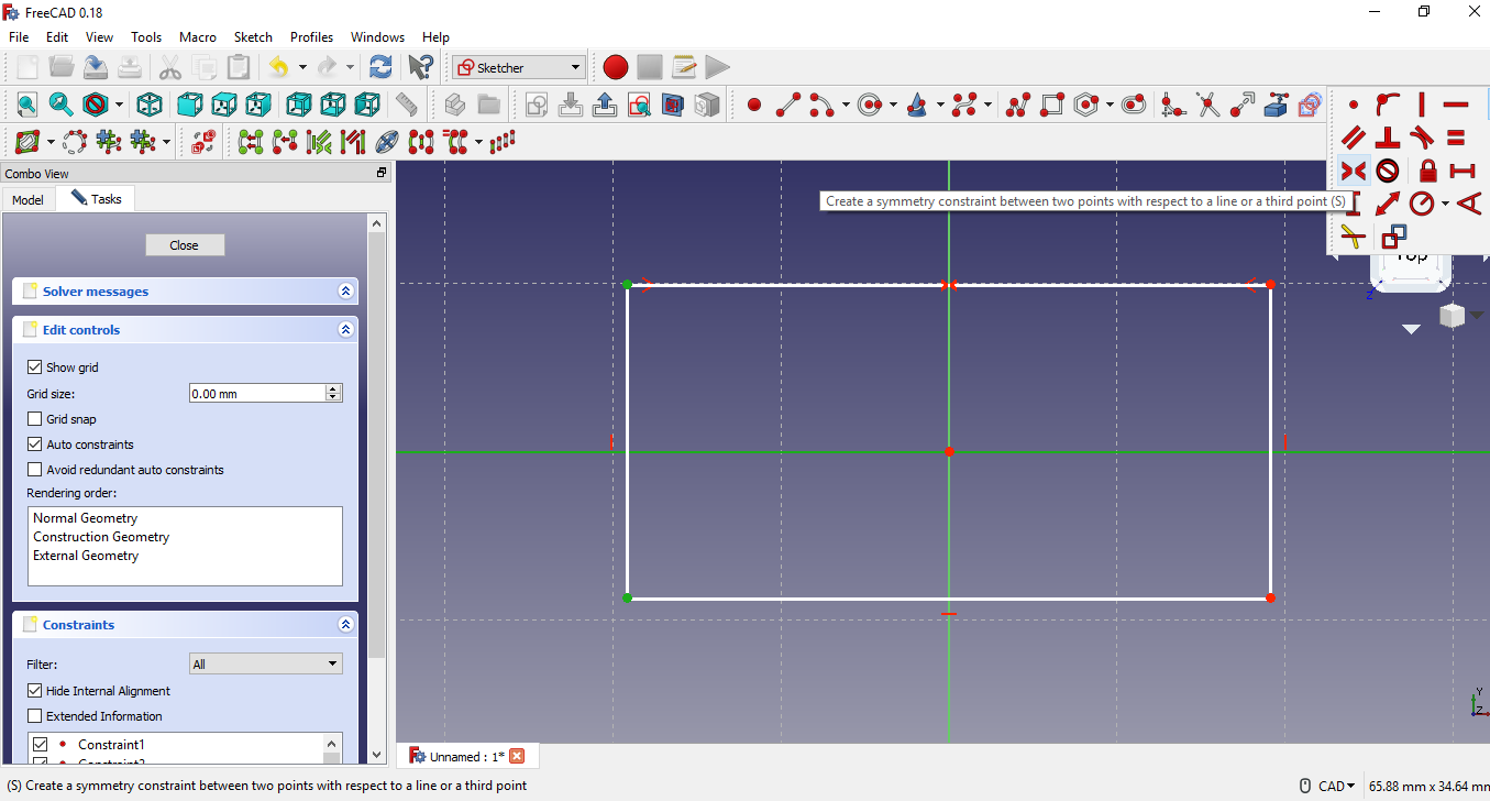
Now we repeat the process for the other axis, select the two points of
the vertical line and the x axis, click on create symmetry.
-
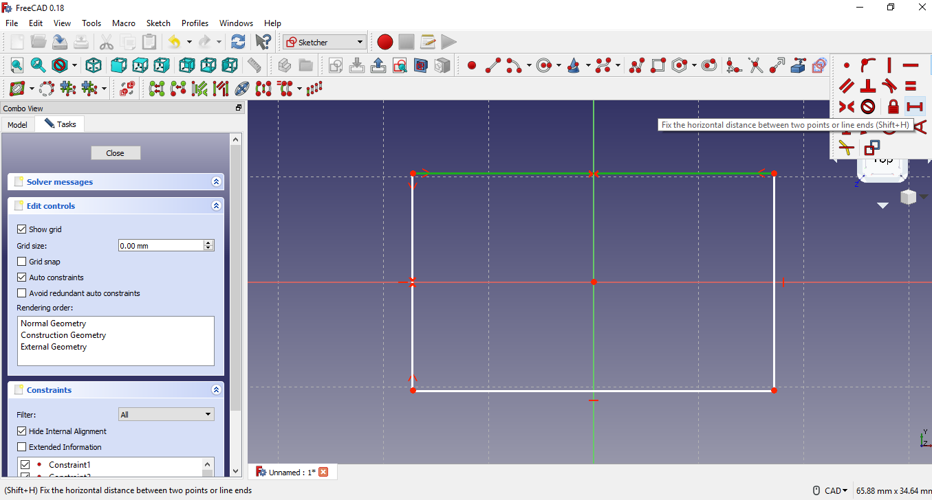
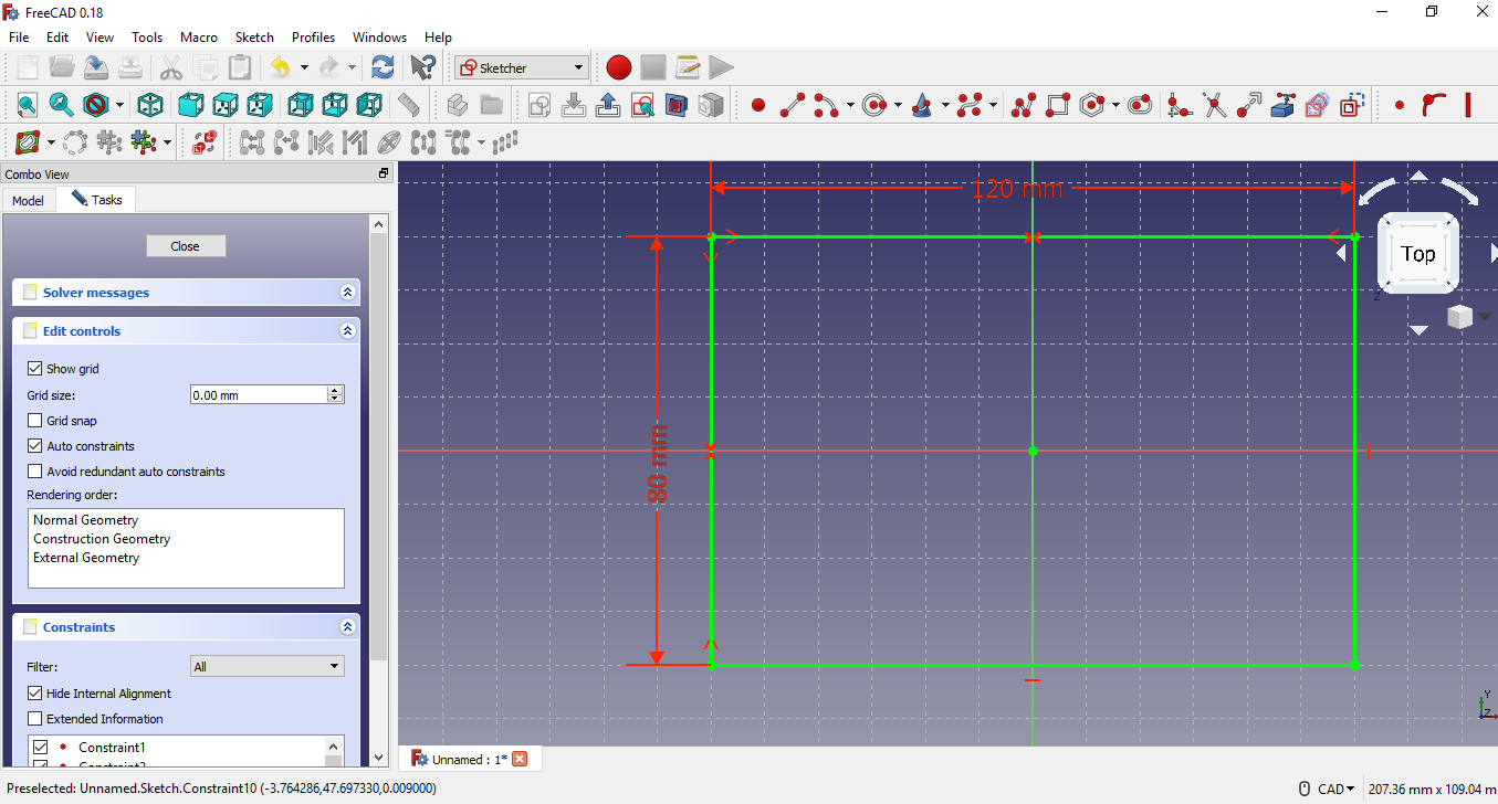
After establishing the measurements for the lines: horizontal 120 mm and
vertical 80 mm, for this I select the horizontal line and write 120 mm,
I do the same with the vertical line and write its value. In order to
measure the lines, there are two icons in the form of horizontal and
vertical rulers.
-
Result.
-
Then I draw a circle at each corner.

-
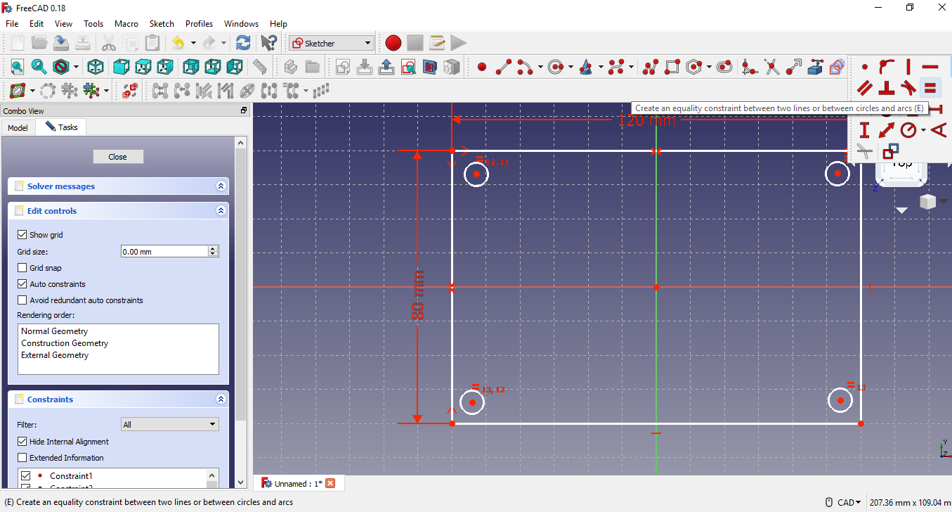
Now select all 4 circles to create an equality constraint, so that they
are all the same size.
-
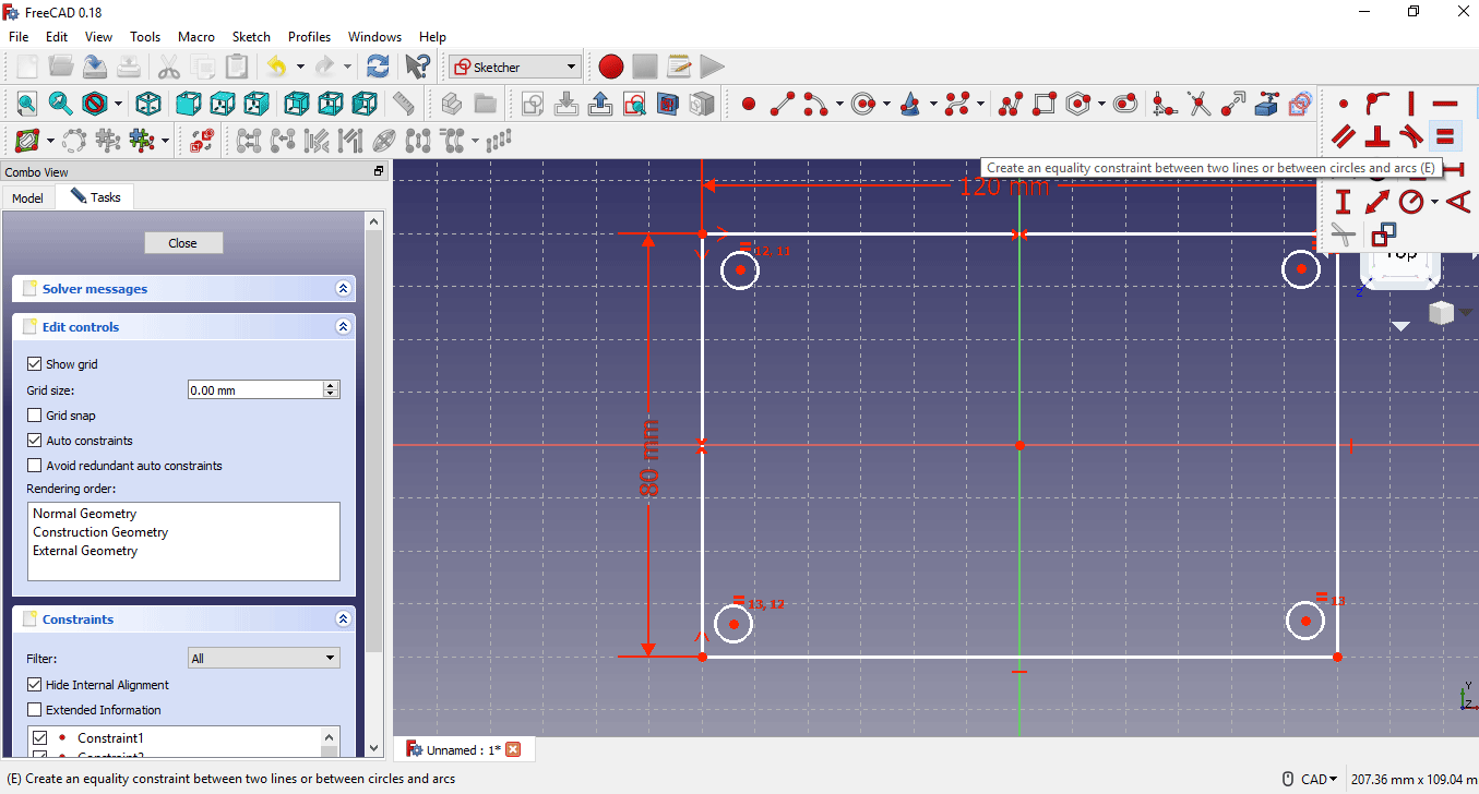
The next step is to give a value of 10 mm to the radius, since they have
equality constraint, it only has to be done in a circle.
-
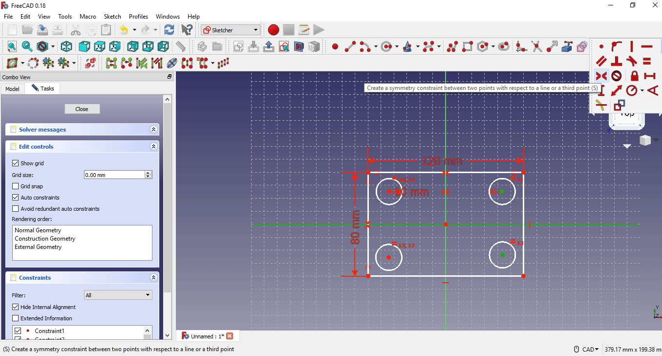
Then symmetry is applied to the center of each circle with respect to
the x axis and the y axis.
-
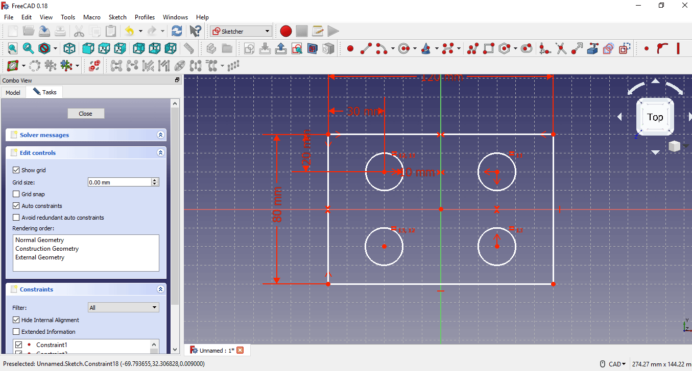
Now I'm going to set a dimension between the center of the upper left
circle and the corner of the 30mm rectangle, the selection is repeated
to set the height of 20mm.
-
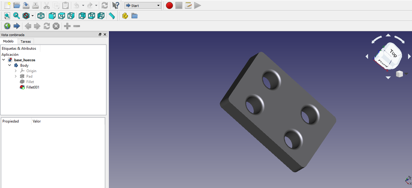
Finally the 2d image is extruded by writing 10 mm.

- 3d image
-
Tutorial
-
I am going to create a design, for it in the menu file section new.
- Rhino
Is a software tool for three-dimensional modeling based on NURBS. It is a computer-aided design software created by Robert McNeel & Associates, originally as an aggregate for Autodesk AutoCAD. The program is commonly used for industrial design, architecture, naval design, jewelry design, automotive design, CAD / CAM, rapid prototyping, reverse engineering, as well as in the graphic and multimedia design industry.
Rhino's interface is a plug-in data exchange processor based on Creo Granite. It can be used to import Rhinoceros * .3dm parts files as parts and assembly files. If there are geometry values on more than one layer in the * .3dm file, the exact geometry values for each Rhinoceros layer will be imported as separate parts with a flat structure set file. The following information is included in each piece through a single import function:
• Surfaces
• Reference curves
• Open fabrics
• Closed fabrics
In addition, each facet body of the Rhinoceros layers is included in the model tree as a separate facet function. Cannot import information into hidden layers. Import DataDoctor can be used to edit import functions. As much as possible, closed fabrics automatically become solid during import. For more information on the following functionality, see the corresponding help modules: • Working with facet geometry: facet modeling in surface design
• Photorealism: photorealistic representation
• Use of Import DataDoctor: Import DataDoctor for data exchange
-
Rhino Commands.
Rhino is a program that works through commands. In other words, all actions are
triggered by commands like Line, Box, or CurvatureAnalysis.
Tip: For more information about a command, use the Command Help panel. Or, run the command and press F1 to open the Help topic.
Commands can be accessed through menus, toolbars, or by typing the command name. In the following sections, we will test the different methods. You will surely find some method easier to use than another. The user has the option to choose the most suitable method and none has preference.
Tip: To cancel a command at any time, press the Esc key.
Toolbars provide a graphical interface for commands. -
Using templates.
A template is a file that serves as a starting point for a new Rhino model. When
starting a new model, Rhino provides default templates that configure the
appropriate units for the model size, some layers, and show a standard four-view
layout.
Custom templates can include any type of document information, such as units, view layouts, layers, and even geometry. If you often create similar models often, set up and save a model as a template (see the Save As Template command in Help). This way, you won't have to waste time setting up your models every time you create a new one. You can start a new model from your template and continue from there. -
For starters I am going to create the model of a bottle in Rhino:
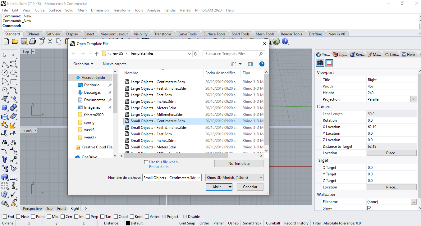
Start Rhino.
On the File menu, click New.
In the Open Template File dialog box, select Small Objects - Centimeters.3dm and click Open.
-
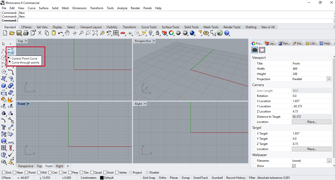
Click on the control point curve icon, this command allows you to create an
image with curved lines, which is required to shape the body of the bottle.
-
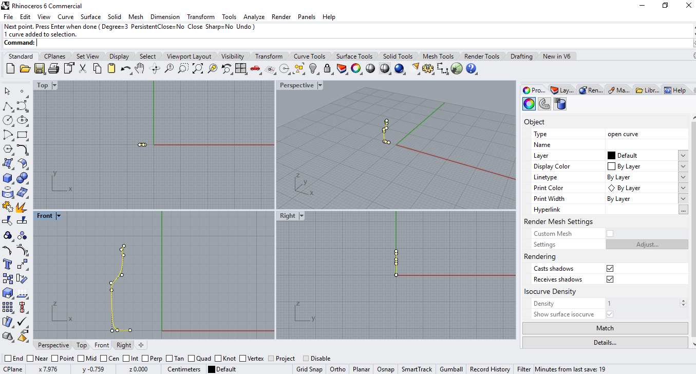
Now we position ourselves in the front view and begin to trace the shape of the
bottle, only half so that with the help of another command the entire shape of
the object is created.
-
Select the designed object, click on the surface shape tool 3 or 4 corner points
(lower right corner) and select revolve.
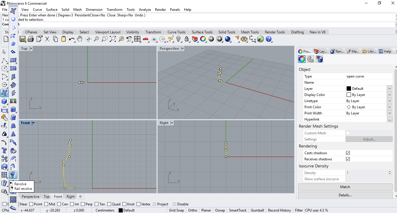
-
Now request that we indicate the beginning and the end, so we draw a vertical
line, at the top we click on the FullCircle.
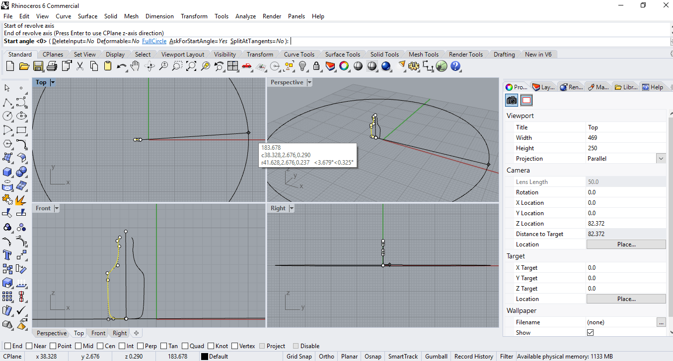
-
To the object is a surface so it is necessary, select the object in the top view
and in the command bar we write offset Srt and click solid.
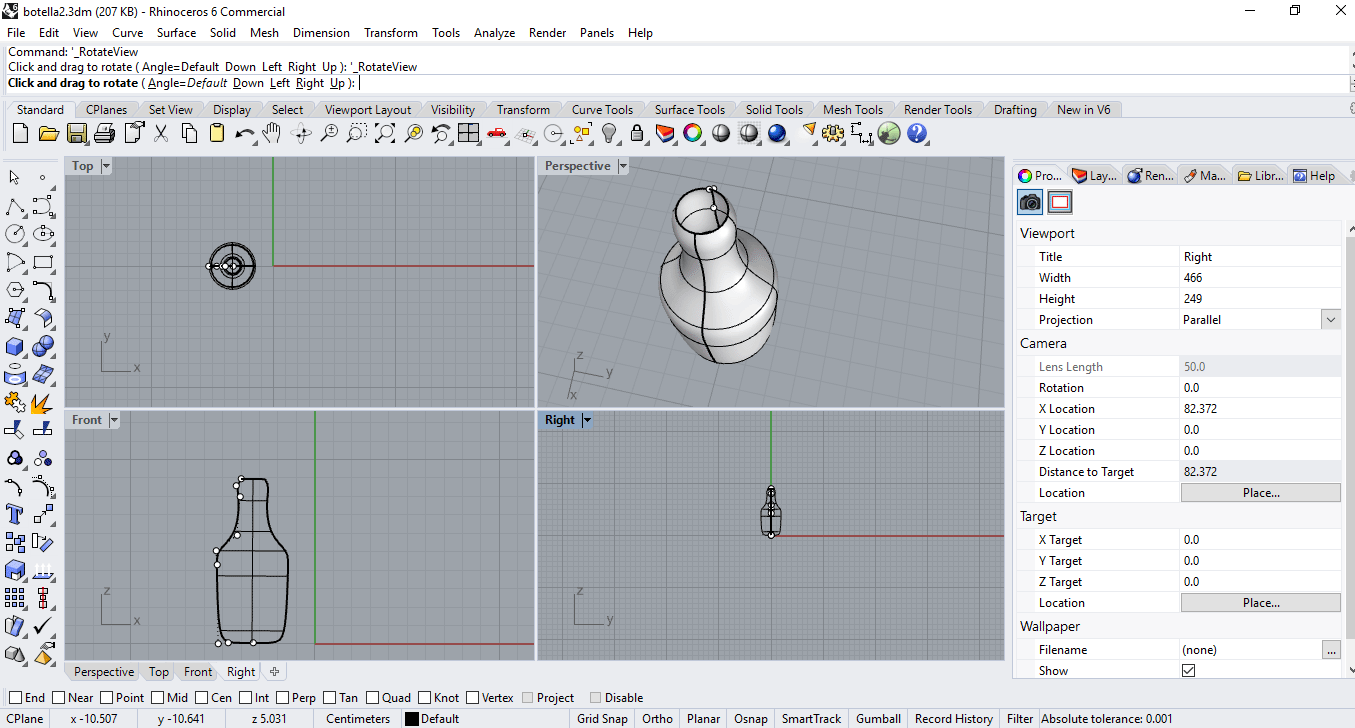
The following video shows some elements of the Rhino graphical interface.
-
Rhino Commands.
Rhino is a program that works through commands. In other words, all actions are
triggered by commands like Line, Box, or CurvatureAnalysis.
- Fusion 360. It is a free CAD / CAM 3D Fusion 360 design software for students and educators. Available for mac and windows operating systems. Tutorial
Possible final project model
I decided to use fusion 360 to do the design, because it is a friendly software and the student version is available. I don't know much about its interface, but I will see tutorials to make 2d and 3d designs.
-
To start with the design, the first step is to choose in the menu file, the option new design in the fusion 360 environment.
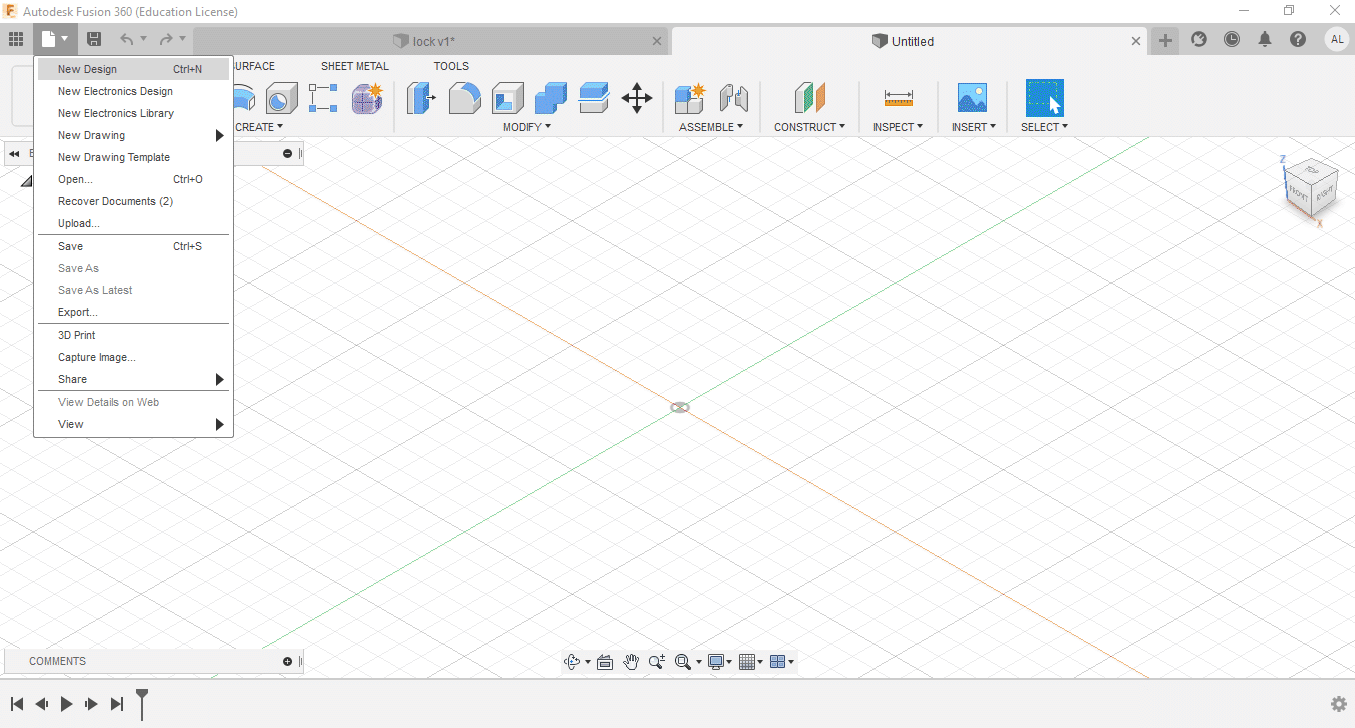
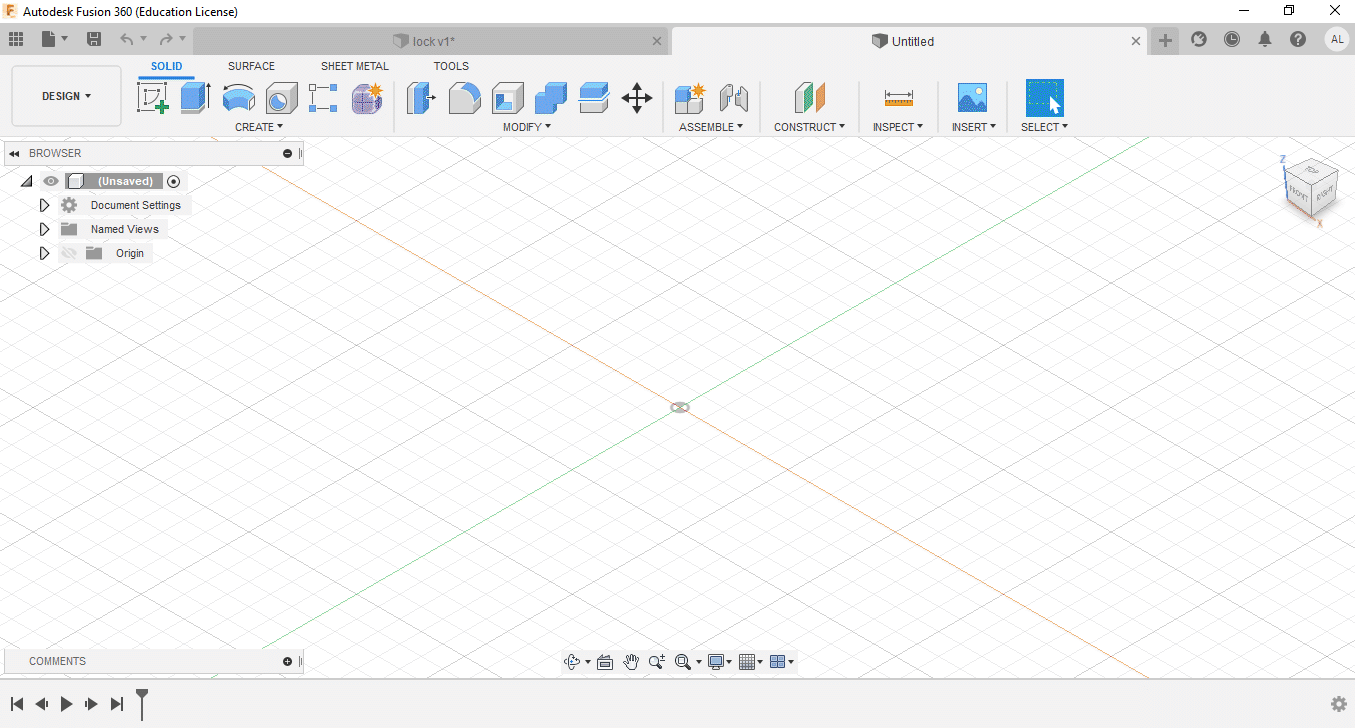
The next step is to create a sketch, for this you have to click on solid, which is at the top, in the image it appears underlined in blue.
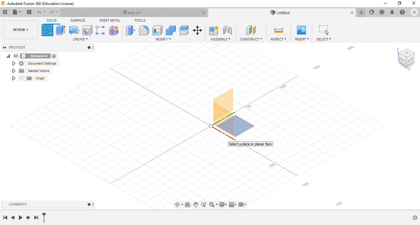
When creating the sketch, it shows the x, y, z plane, here you just have to click on the plane that you decide to use, it is suggested that it be in the x, y plane, each plane is identified by a color, as can be seen in the picture.
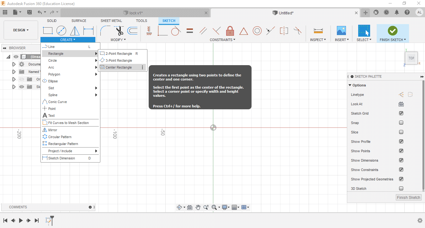
On the create option (available within the sketch) click and move the mouse to rectangle and select center rectangle. This allows you to create the rectangle centered at the origin.
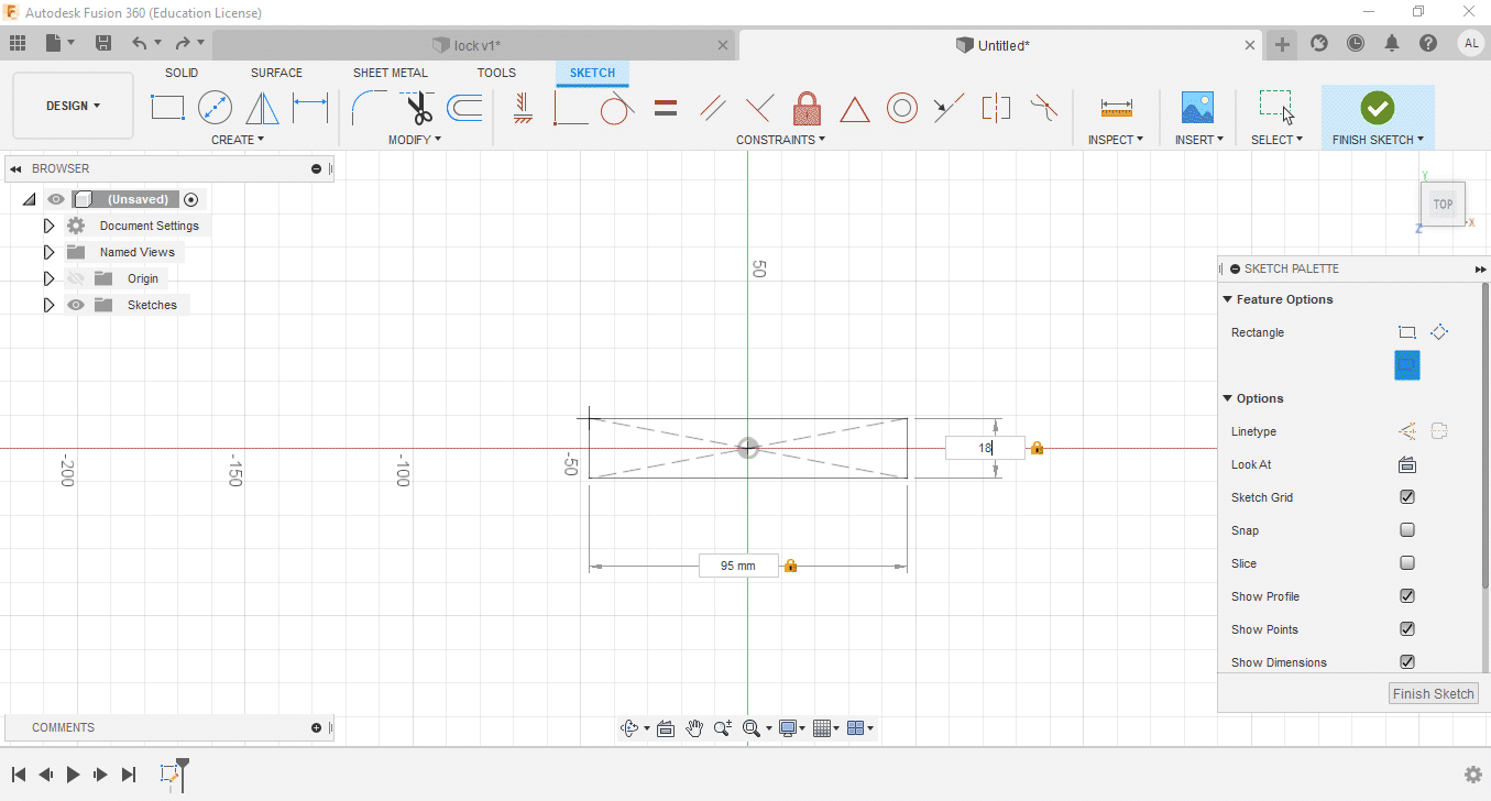
The next step is to click in the center of the plane and move the mouse, write the first value and with the tab key you change the position to modify the second value that is given to the rectangle (95x18mm). These dimensions are the actual sizes of the lock I am using.
The next step is to draw the second rectangle of 44x3mm, for this a rectangle is created using two points, after choosing this tool, click on the lower point of the right loop of the first rectangle and move the mouse and follow the same procedure to assign the values to each side.
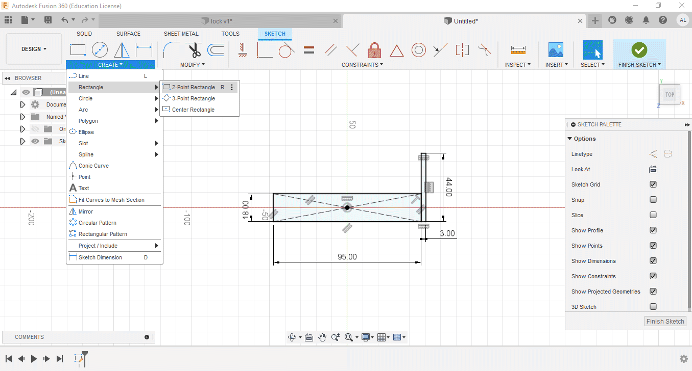
After taking some measurements of a real padlock, I made the basic shape of a padlock, creating a sketch with 2 rectangles
-
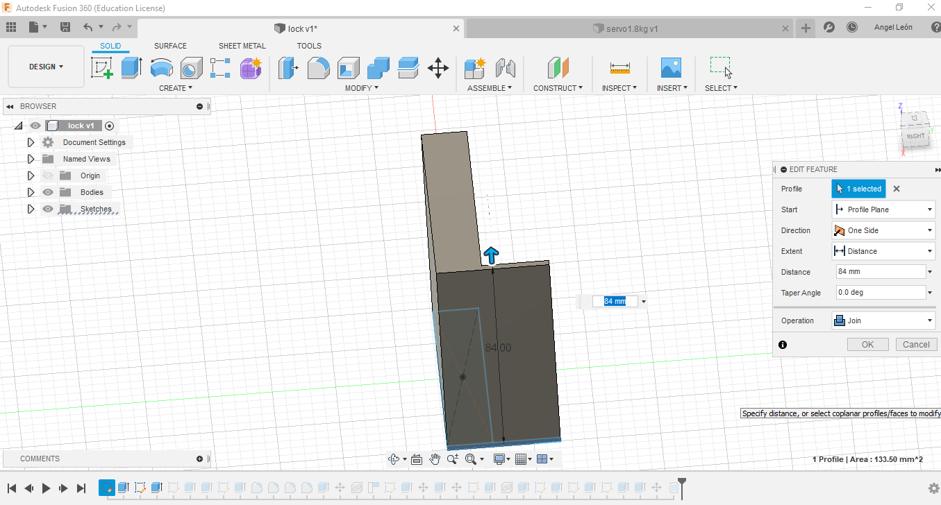
To extrude I select the rectangles and press the letter e and assign a value of 84
mm.
-
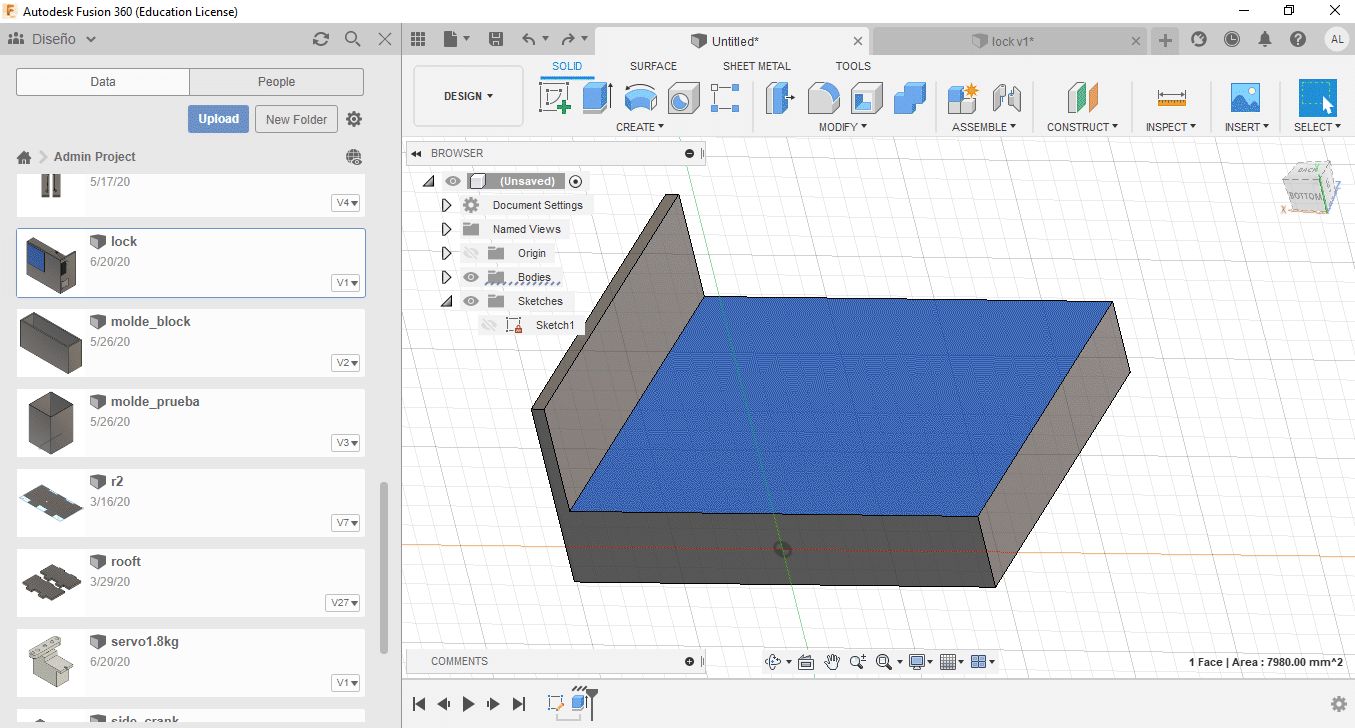
To give depth to the first rectangle created, you must select the top part and create a
sketch on it.
-
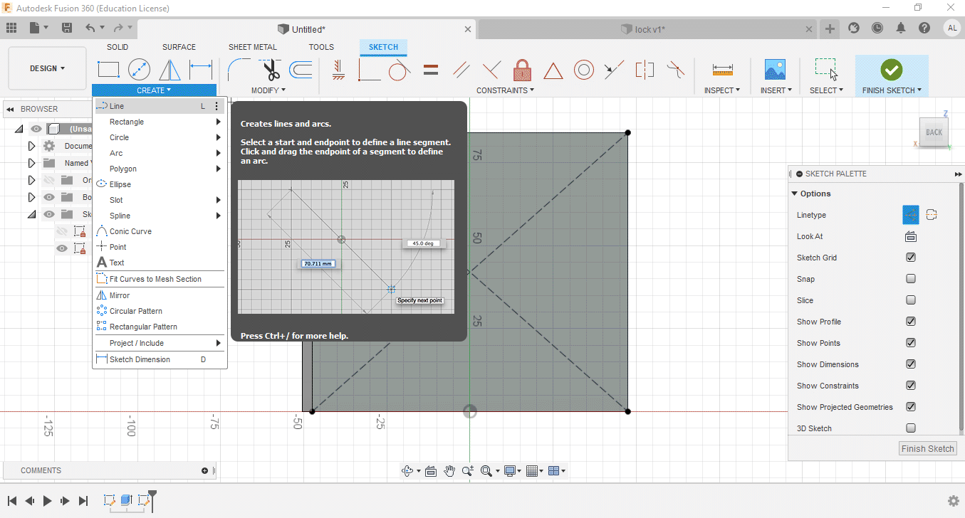
To locate the center we are going to draw two diagonal construction lines (in line type
select construction).
-
Now you have to draw a central rectangle. Remember to click on the line type so that it
is not a construction line. You must finish the sketch.
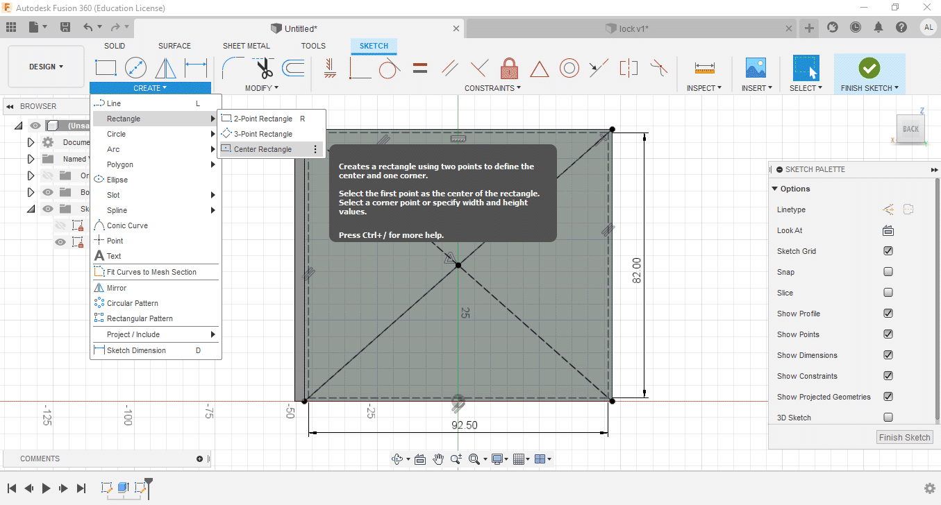
-
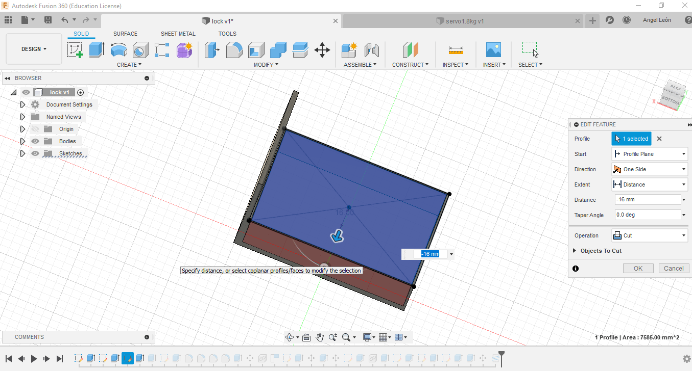
Then, to remove the interior, the next step is to extrude the created rectangle -16 mm,
for this you have to select it with the mouse and press the e key.
-
Now you have to draw construction lines, which serve as a reference to create the shape
of the holes that the front view will have.
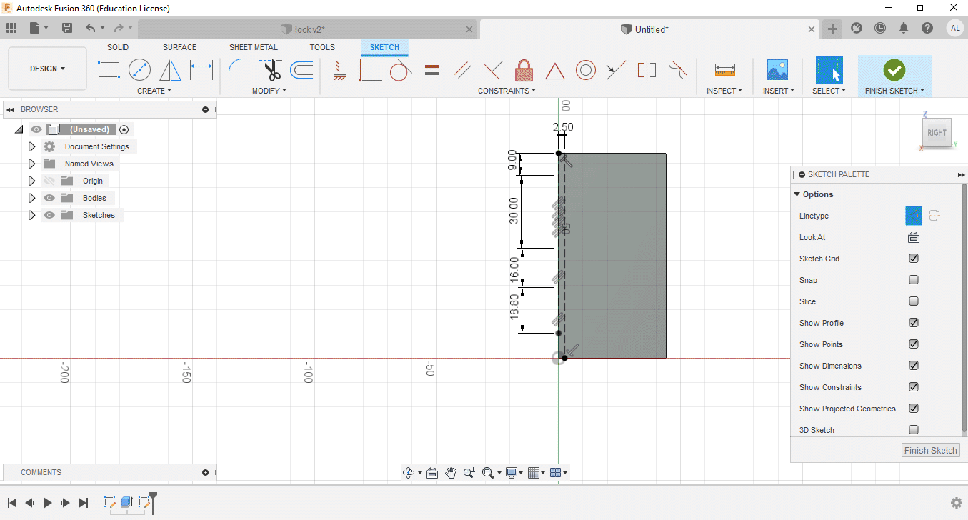
-
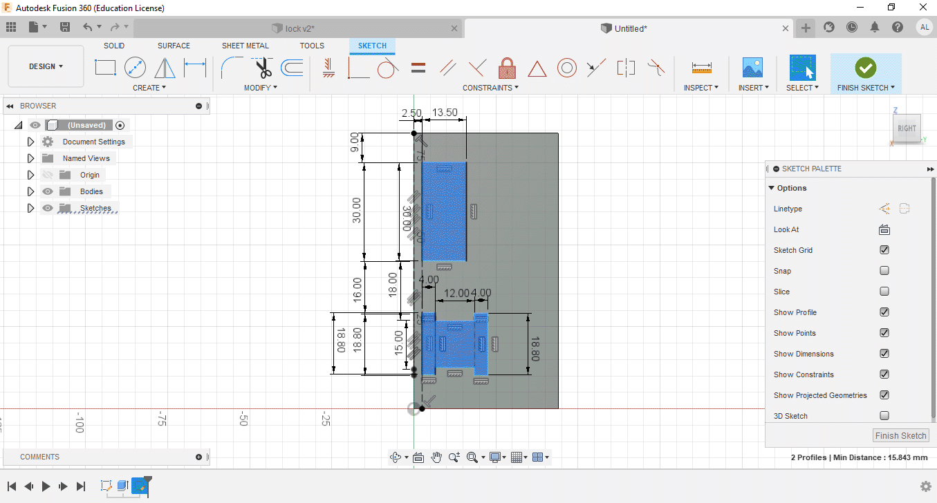
Once all the construction lines have been defined, a rectangle with 2 points of
30x13.50mm must be created (remember to remove the line type selection, otherwise the
shape will not be created). For the other shape it is created with lines, joining the
external points and thus creating that shape.
-
To make some holes, design on the side with the largest dimension, this taking the real
lock as a reference, using the line tracing tool. Although the lock is not going to be
manufactured, my idea is to learn to use the tools.
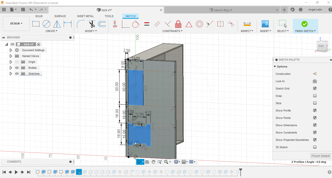
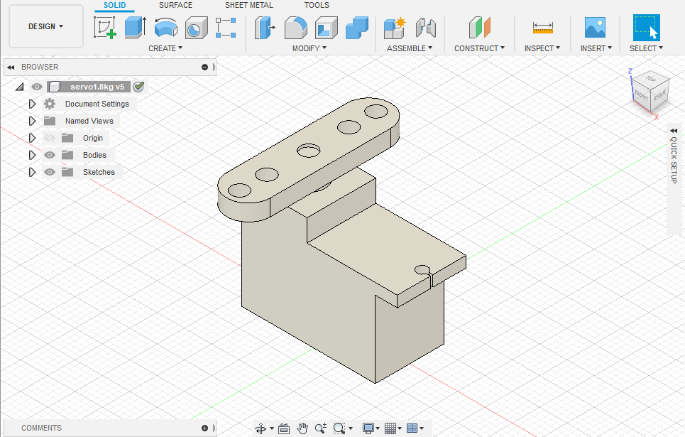
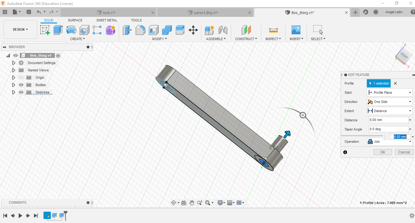
- Then, I did another two components in different files, by drawing simple shapes,
like rectangles, circles, and extruding them.
One component is to represent a servo, the other is an object that will connect
the servo with the metal part of the lock that locks the door
-
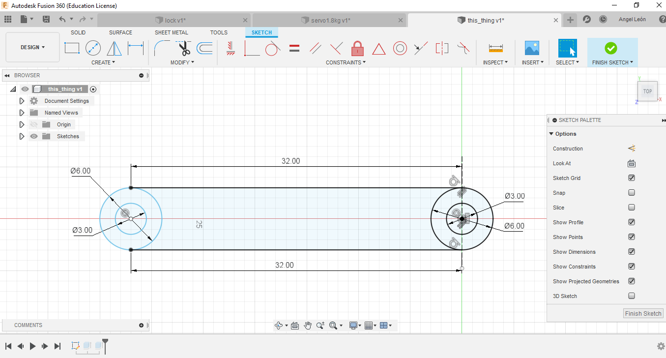
This piece is to unite the servo with the component of the lock, which will allow to
open or close, for the design use lines and circles of 2 points.
-
I select the design and extrude it 4 mm.
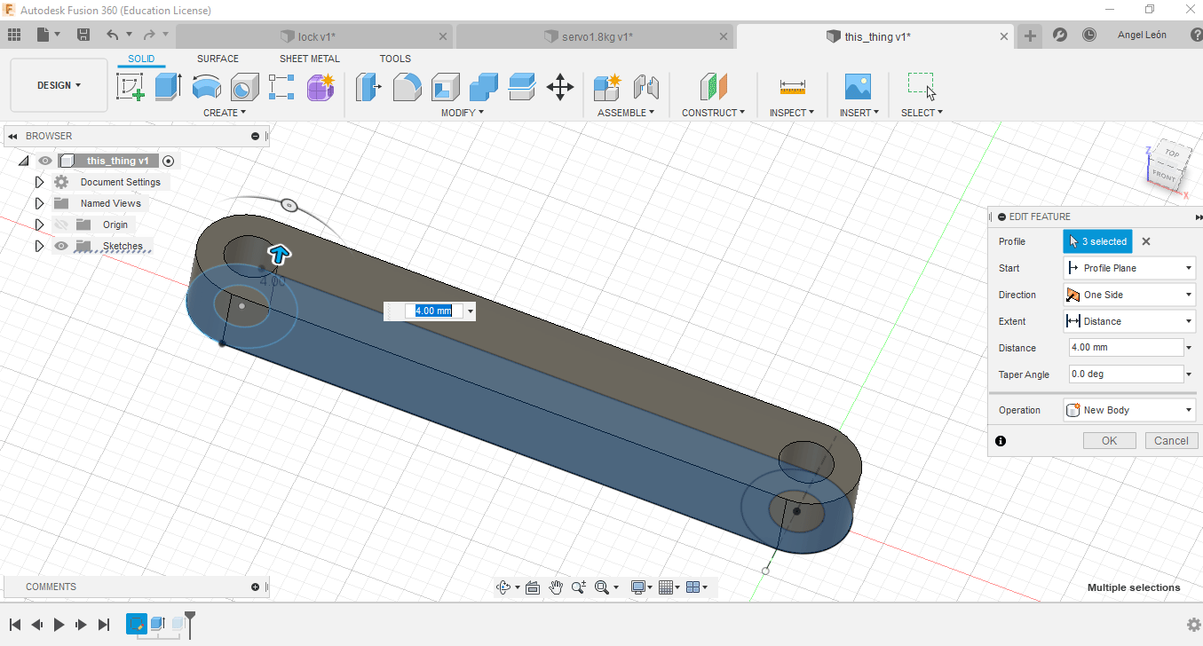
-
I select the inner circle and extrude it 8 mm.
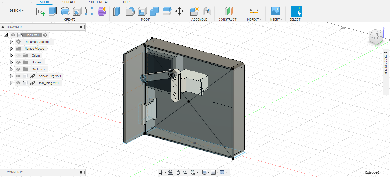
- Finally, I added the 2 components into the main file, and after adding another few simple pieces like a rectangle to represent the metal thing that locks the door, the model is done.
