12. Output devices
- Individual assignment:
Add an output device to a microcontroller board you’ve designed, and program it to do something.
- Group assignment:
Measure the power consumption of an output device.
12.1. Individual assignment
This week I have to program a board with output devices. In my final project I need to control a mini water pumps and RGB LEDs in synchronization with the music that the microphone picks up. I already did the board design in INPUTS week.
You can download Eagles files here.
The OUTPUTs components are:
My board must control the speed of the pump. Initially I thought about using a DC motor driver. The drivers I have are A4953ELJTR-T, DRV8838DSGR, A5940GLKTR-T and A4982SLPTR-T. After seeing their datasheet I check that for a 5v DC brush motor I can only use the DRV8838DSGR, but it is too small to mill the tracks with the tools I have (0.25mm space between tracks). I have tested the pumps with more voltage and they work, so I decide to use the A4953 driver.
On the other hand, the WS2812B LEDs are addressable, they are connected in a chain requiring 3 pins (GND, VCC, DATA). They can be powered at 3.3v-5V. I’m going to feed them at 3.3v. To control them I use the library for Arduino IDE “Adafruit_NeoPixel.h” . There is also another library “Fastled.h” very similar.
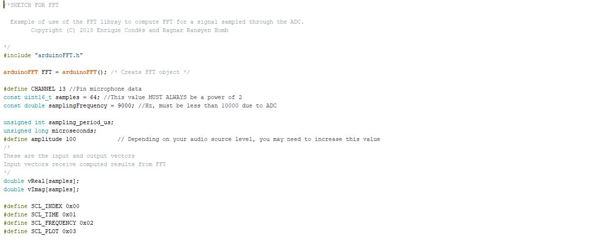
This is the script:
First I declare the variables and libraries that I am going to use.
I start with the library “arduinoFFT.h” . This library analyzes the incoming sound from the microphone by measuring the intensity of each frequency band that makes up the sound.
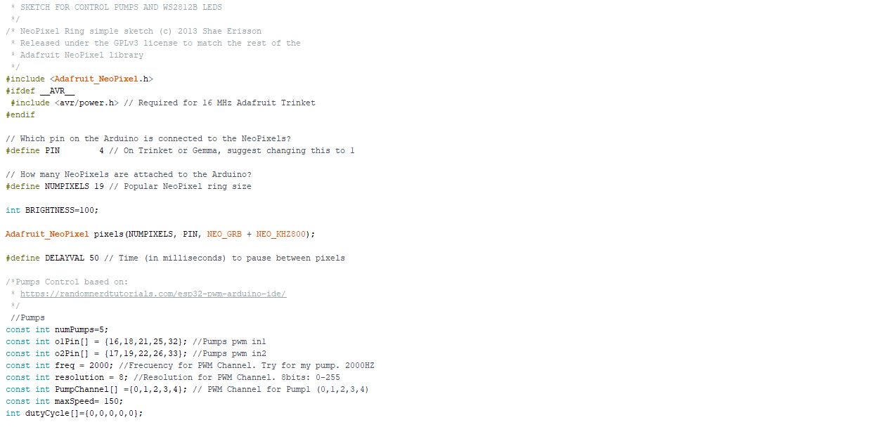
Next I include the library “Adafruit_NeoPixel.h” and declare its variables.
-
NUMPIXELS indicates the number of LEDs that make up the string. For the first tests I put 1, but finally I put 19 leds.
-
BRIGHTNESS It is the brightness of the LEDs. From 0 to 255. I choose 100 because it shines enough and consumes less intensity.
I also declare the variables to control the speed of the pumps. Using ESP32 to generate PWM signals is different from other microcontrollers. It is necessary to clear a channel for each different signal.
- maxSpeed limits the maximum for the PWM signal. I use it so that the jets of water do not come out of the source.
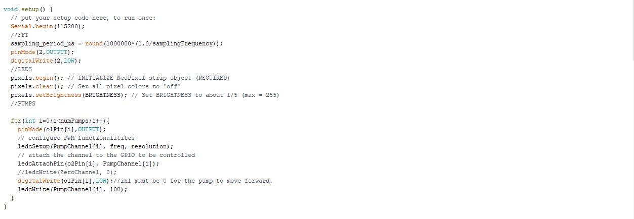
In the function setup () I initialize variables. Note that to configure the PWM signals of the pumps in the ESP32, you have to use specific functions (ledcSetup, ledcAttachPin and ledcWrite).
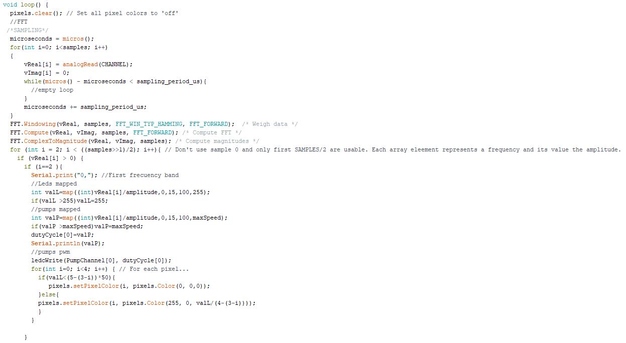
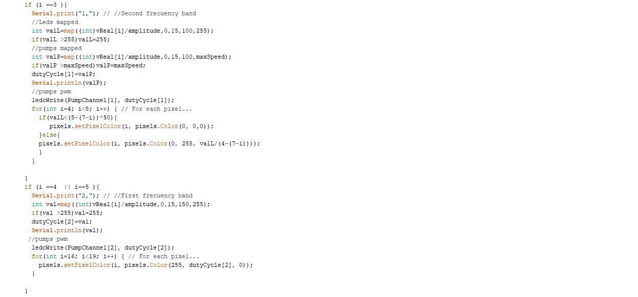
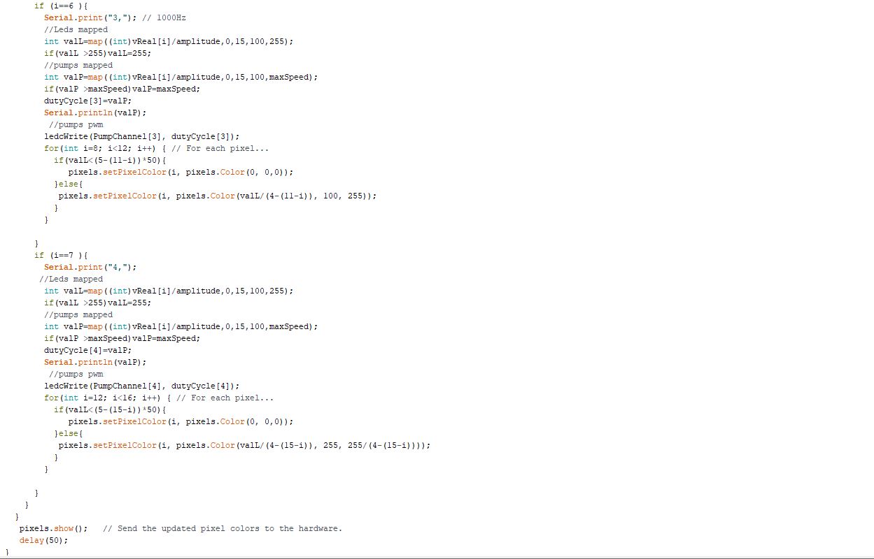
In the loop () function I analyze the sound and relate the value of each frequency band to the speed of a pump and its LEDs.
- Test 1. 1xpump and 1xled
- Test 2. 5xpumps and 1xled
- Test 3. 19xleds
You can download scripts here.
12.2. Group assignment
The Group Assignment page is at the following link.
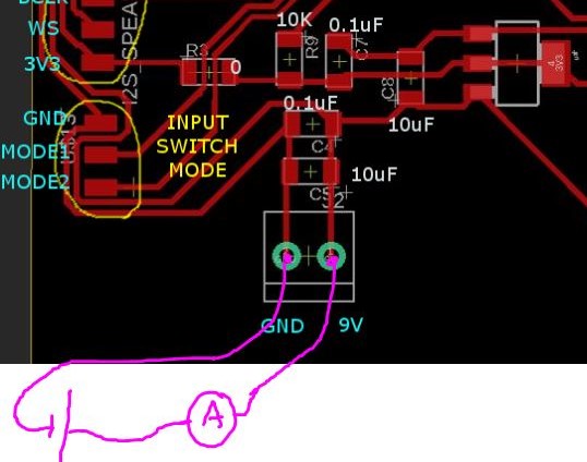
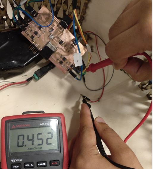
I’m going to measure the consumption of my source.
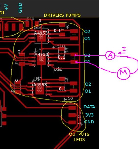
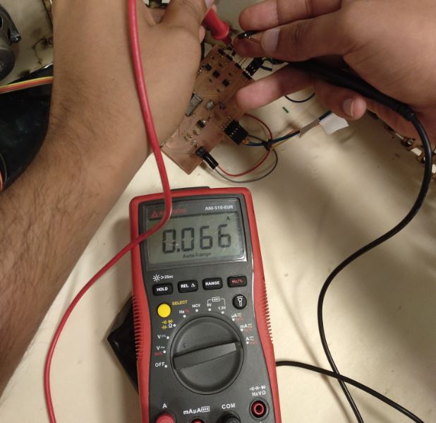
First I measure the consumption of a pump. Ip = 0.066A
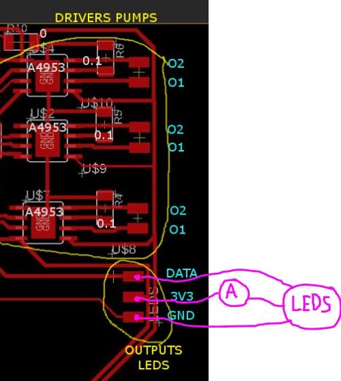
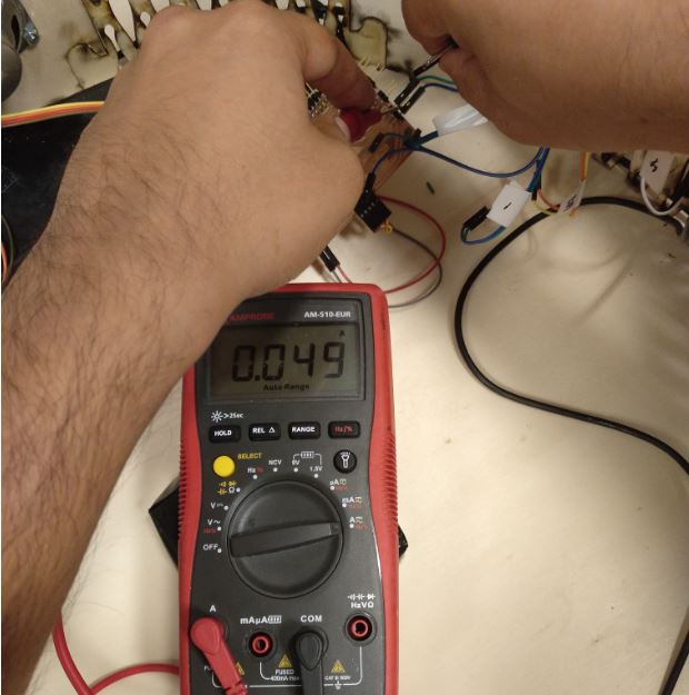
Then I measure the consumption of the 19 LEDs. Il = 0.05A
Finally the consumption of my board with the microphone, 5 pumps and 19 leds. It = 0.452A.