8. Computer controlled machining
-
Group assignment
- Test runout, alignment, speeds, feeds, and toolpaths for your machine.
-
Individual assignment
- Make (design+mill+assemble) something big.
8.1. Group Assingment
The Group Assignment page is at the following link.
Our milling machine is the SW1325 de CNC Barcenas.
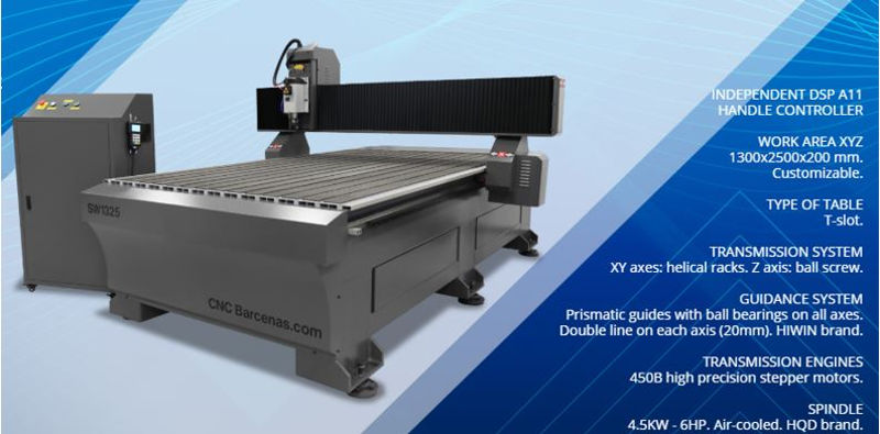
Other features:
-
Maximum speed:
-In air: 20 meters / min.
-At work: 15 meters / min.
-
Resolution +/- 0.05 mm.
-
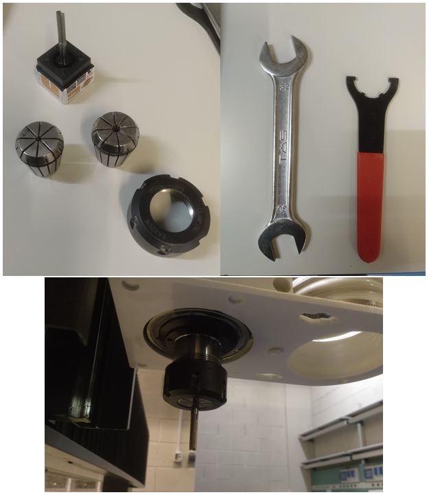
Electromandrino
Brushless high frequency motor with air-cooled ceramic bearings. Power 4.5 KW. - 6 CV. · ER32 milling cutters from 1 to 20 mm. From 4,500 to 18,000 rpm. with adjustable speed from the machine. Capable of reaching 18,000 rpm. and perform great works of cutting, carving, 3D reliefs on wood, plastics, resins, foams and a multitude of materials.
8.1.1. Aspire software
To generate the G-Code we use Aspire software. We design a part for the feed rate test. These steps will be general for all milling we do.
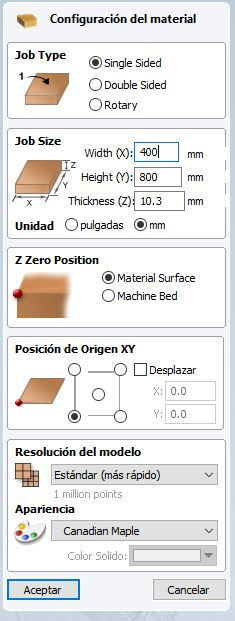
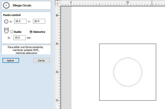
- We set the dimensions of the work material and the reference point for the Z Zero.
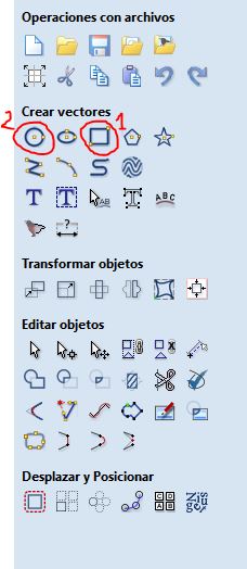
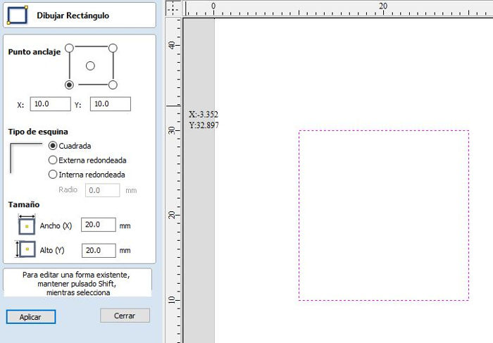
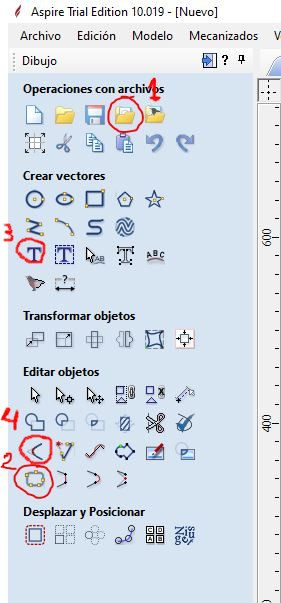
- We use the tools to create vectors to draw the piece (1)(2). We will draw a square, whose perimeter we will mill with a depth equal to the thickness, with a circle inside whose surface we will mill 1.5mm deep.
-
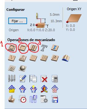
Selecting each vector (rectangle and circle) we configure the type of operation we want to perform. Basically, we will use 3 types of operation:
-
1 Profiling operation. We use this operation to mill the vectors perimeter. Useful for cutting outlines.
-
2 Pocketing operation. We use this operation to mill the inner surface of a closed vector. Useful for engravings y joints.
-
3 Drill operation.
-
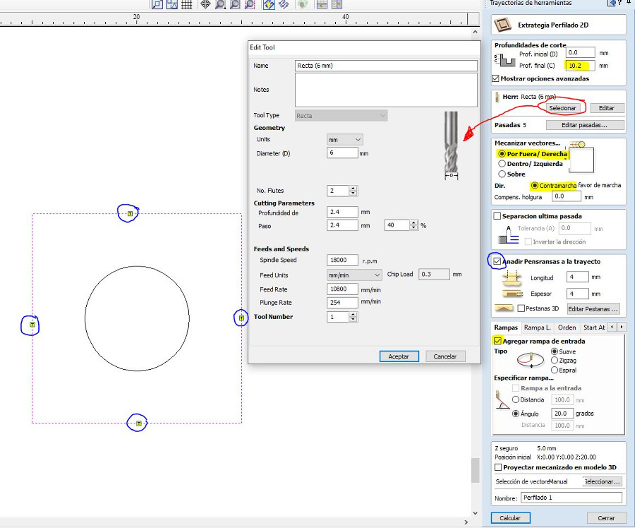
- For the rectangle we use a profiling operation. We set the cutting depth equal to the thickness of the material (or slightly higher to make sure we cut the bottom surface). We select the tool. We select the type of machining of the vectors “Outside / Right” and “Countermarch”. Add Penransas so that the piece is fixed throughout the milling.
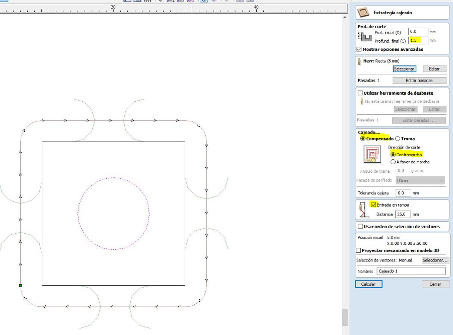
- For the circle we use a pocketing operation . We set the depth of cut equal to the thickness 1.5mm We select the tool .
- We can see a simulation of milling operations to check that everything is correct.
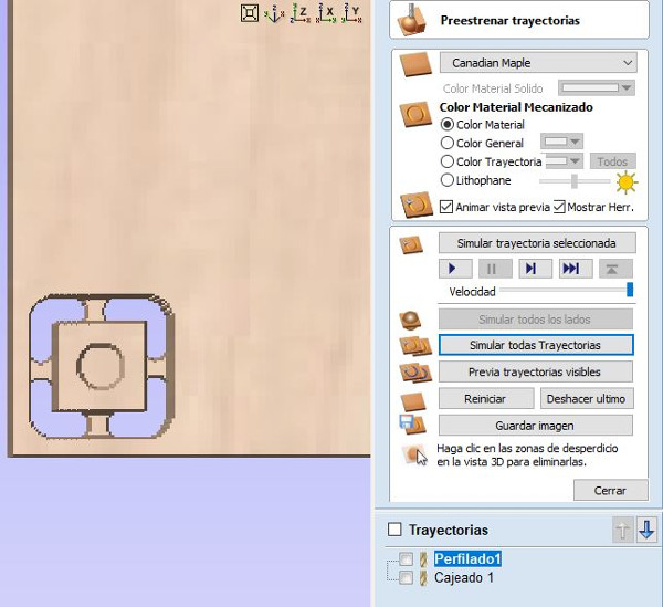
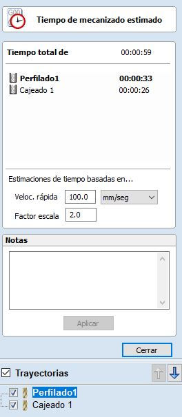
-Next we can see an estimate of the time that each operation will spend.
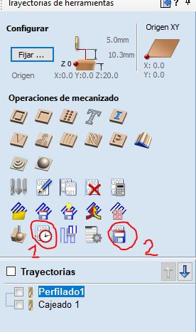
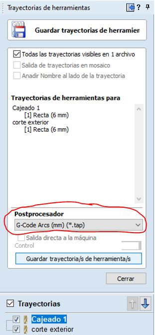
- Finally we save the G-Code file on the pendrive. For our machine we have to select the Postprocessor “G-Code Arc (mm) (* .tap)”
8.1.2. Operating the milling machine
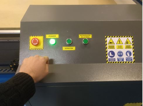
1.- Turn on the router.
2.- Insert the pendrive in the DSP with the files in Postprocessor format “G-Code Arcs (mm) ( .tap)” or “ISO plain G-codes-mm ( .iso) for the 4th axis”.
3.- Do HOME. The DSP will display: HomeTypeAtStart.
3.1.- Press axis home and OK key. The machine will be positioned at its starting point. The X axis to the left, the Y axis to the top of the table and the Z axis above. 3.2 The machine is now ready to work. This step is essential for the proper functioning of the machine. ALWAYS have to do HOME.

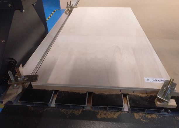
4.- We place the workpiece and hold with grips.
5.- We position the machine in the XY0 point previously marked in the software, generally the lower left point is used.
5.1.- Once the milling cutter is in the desired position, we will mark XY0 by pressing the ON / OFF + XY0 key. Once pressed, the DSP will indicate the X and Y axes at 0.
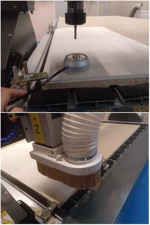
6.- Position the Z0 of the machine: We will put the milling cutter of the machine in a position of the material that is flat:
6.1.- WITH SENSOR: We will place the height sensor under the milling cutter (without touching it) and on top of the material. We press ON / OFF + MENU. First we will press the MENU key and without releasing we will press ON / OFF, we will now release both keys at the same time. The motor will slowly lower and the cutter will touch the height sensor, when it touches the Z axis will go up and the height taking will be finished.
6.2.- WITHOUT SENSOR: We locate the position we want and press ON / OFF + ZC0 and then mark CLEAR Z.
7.- Once we have the XY0 and the Z0 we can press ORIGIN / OK (in case we have moved the axes) so that they return to 0. It is not a necessary step since the DSP has already saved the XY0
8.- Set the axis of rotation to 0: Press ON / OFF + ZC0 and then mark CLEAR A.
9.- Load the machining files.
9.1.- We press RUN / PAUSE DELETE and the DSP will show us two options. Here we must choose where we have saved the machining file. The 1st option (U Disk file list) is the one we will use since we will always use the pendrive. We therefore press ORIGIN. 9.2.- The DSP will show us a list of the files that are on the pendrive. We will move to the file we want and accept it with the ORIGIN / OK key.
9.3.- Next we must adjust the machining settings, which is as follows:
-
WorkSpd: Work speed when the cutter touches the material. Engraving and cutting speeds can range from 2000 to 6000. For more delicate operations we can reach 1000-200. The operator’s experience will tell these values.
-
FastSpd: Working speed when the cutter moves in the air. Maximum movement speed of the milling machine.
-
SpdScale: 0.500. Percent of WorkSpd speed at which the mill will begin work.
-
FallDown: 0.5. Do not modify this value.
10.- Press ORIGIN / OK and the job will start. And turn on the aspiration.
11.- While the work is being carried out we can make the following changes:
- Change the speed to the motor: Z + or Z-. From 1 to 8 speeds.
- Change the working speed: Y + or Y-. From 0.1 to 1.00 (it would be from 10% to 100%).
8.1.3. Runout
Runout is the tendency to rotate the tool around a center point that is not the center of the tool. Causes the tool to wobble rather than rotate cleanly and increases chip loads. It is very bad for the useful life of the tool, so it is good to know more about it.
It must be taken into account if it is observed that the milling machine changes its behavior. In principle our milling machine should not give problems because it is new.
8.1.4. Alignment
To ensure that the milling work does not come out of the work material, it is important to ensure that the edges of the material are aligned with the axes of the machine, especially for large milling.
To achieve this we follow these steps:
-
Align the work material with the edges of the hammer material, which should be aligned with respect to the machine since it touches an edge of the work table.
-
Check the alignment by moving the spindle along the x and y axes and measuring the distance to the edge.
8.1.5. Feed Rate
We have found information on how to calculate it on this website.
The feed rate used depends upon a variety of factors, including power and rigidity of the machine, rigidity of part hold-down, spindle horsepower, depth and width of cut, sharpness of cutting tool, design and type of cutter, and the material being cut.
One thing to remember is to make chips not dust. Chips will help by removing the heat produced in the cutting process thus increasing tool life and improving edge quality.
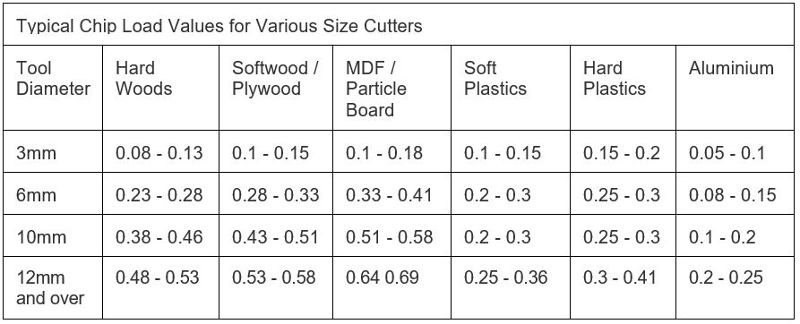
Feed rate is calculated using the following equation:
Feed = N x cpt x RPM
N - number of cutting edges (flutes)
cpt - chip load (chip per tooth) is the amount of material, which should be removed by each tooth of the cutter as it rotates and advances into the work. (mm per tooth)
RPM - the speed at which the cutter revolves in the spindle. (Revolutions per minute)
Feed Rate calculation
-
Material: Plywood wood, width = 10.2 mmm approx.
-
Milling tool: Straight flute type, d = 6mm, N = 2 edges.
-
Chip Load: According to Chip Load table, ctp = (0.28-0.33)
-
Calculation:
Feed = N x cpt x RPM
Feed = 2 x 0.3 x RPM
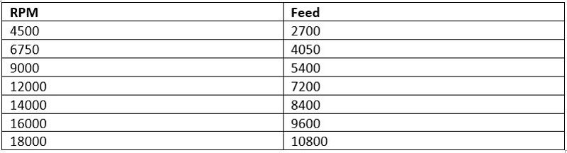
We will test milling at different speeds taking the calculated speeds as a reference.
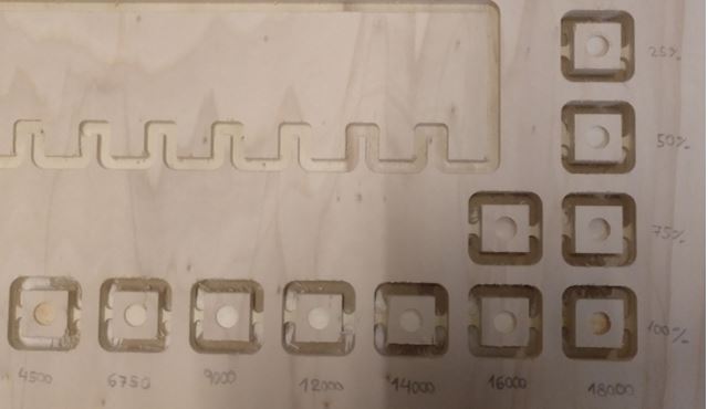
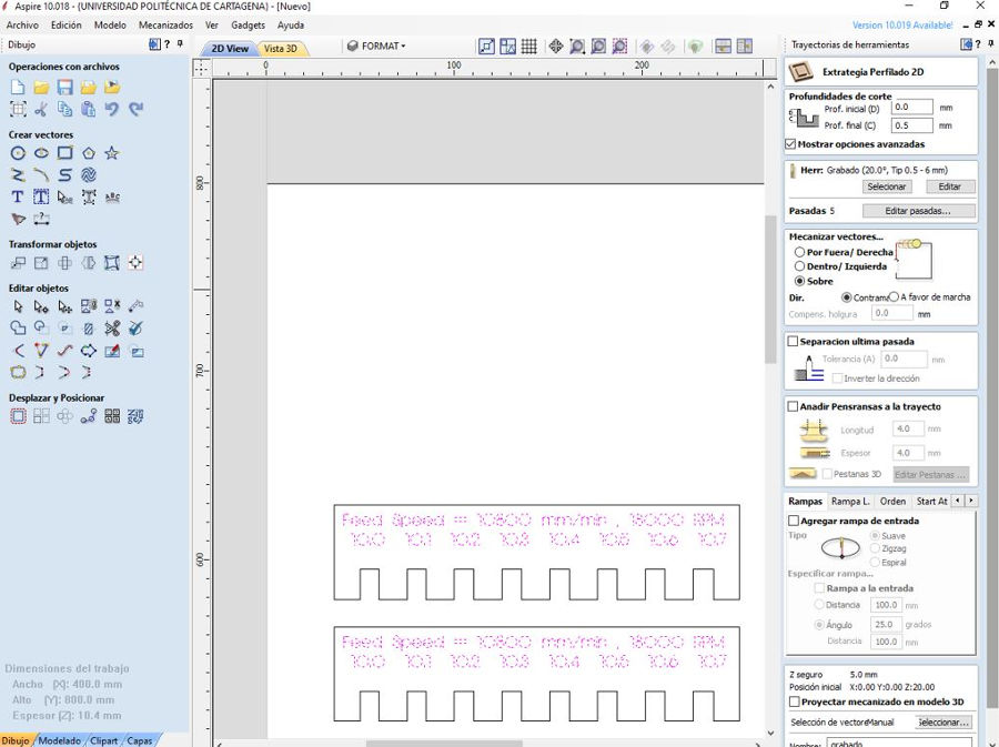
We have made the cut at different speeds of Spindle (the speeds that the machine allows) and rate speeds (starting from the speed that we previously calculated). There is no great difference in the surface finish. It seems that at 18,000 RPM and at 10,800 mm / min the result is somewhat better.I also haven’t seen smoke come out at low rate speeds
8.1.6. Pressfit test
To check the pressfit we have designed a piece with different lace measurements. We have cut it with the following parameters: 10800 mm / min and 18000 RPM with the milling tool (Straight flute type, d = 6mm, N = 2 edges). In addition, we engraved a text at a depth of 0.5 mm with a V Carving type mill 20º x 0.2 x 3 mm.
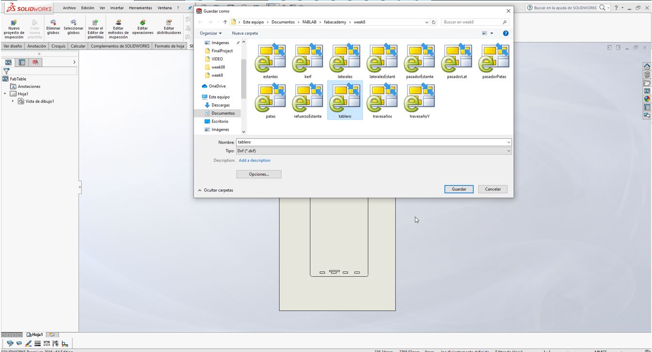
El diseño lo he hecho utilizando Solidworks. Creo un dibujo a partir de la pieza y exporto la imagen como dxf.
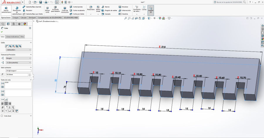
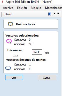
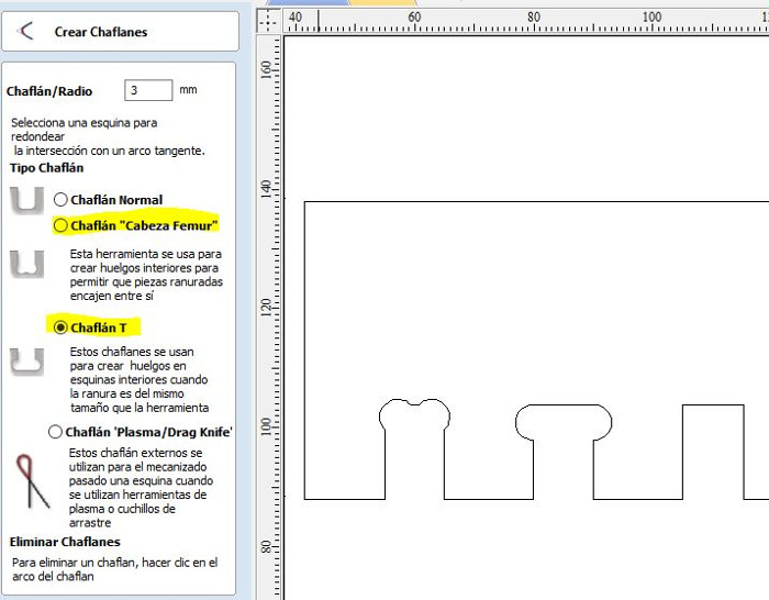
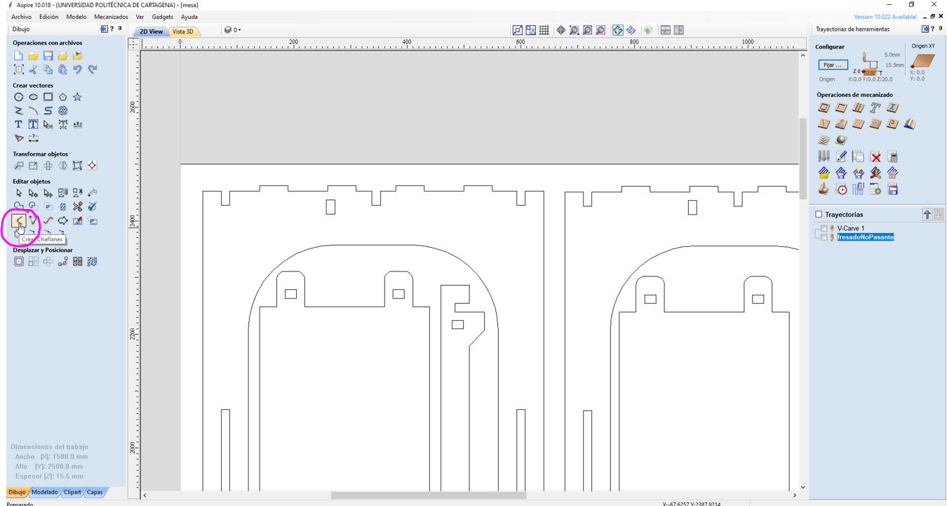
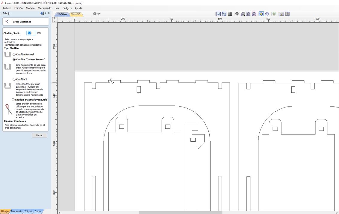
To import vectorized images as dxf in the Aspire software we have to click on “Import vectors from a file” (1). And then make sure that the contour is closed by clicking “join open vectors” (2). Also we have added a text to record the measurements of the different pressfits using the “Draw text” tool (3). Finally, we have used the “Create chamfers” tool (4) to round the inner corners that the cutter could not enter. We use the T-Bone y Dog-Bone types.
Results:
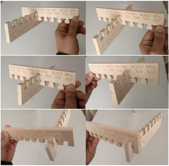
The greatest tightening I get with 10.02 mm although it costs a little to fit the pieces, therefore when designing joints we will take the same thickness of the material as a measure.
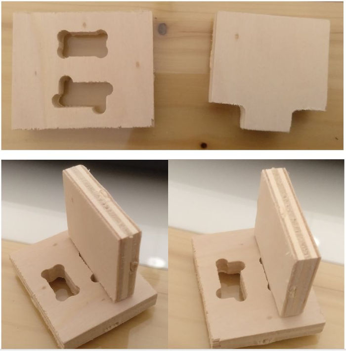
We have also tried other joints.
8.2. Individual Assingment
I have to design and build something big. I thought about making a piece of furniture for my FabLab. We need a table with shelves to optimize space in a cubicle. This is my design.
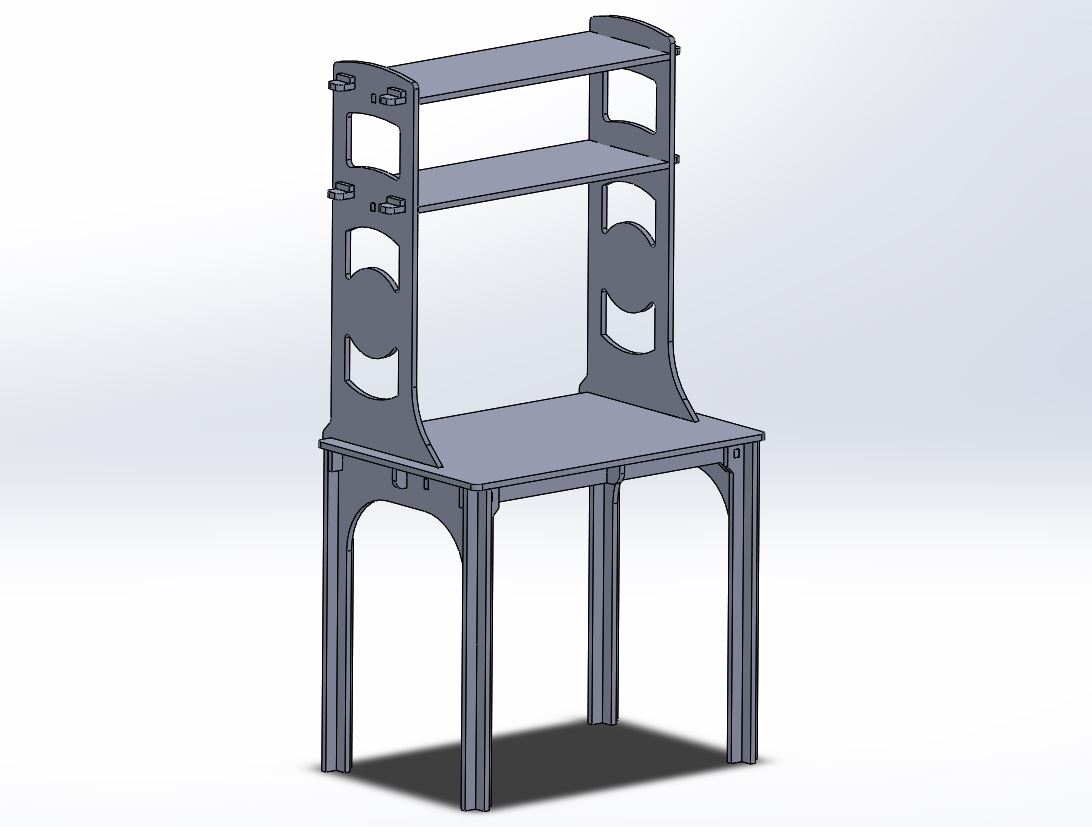
It is a large piece of furniture, so I will have to reinforce the structure quite a bit.
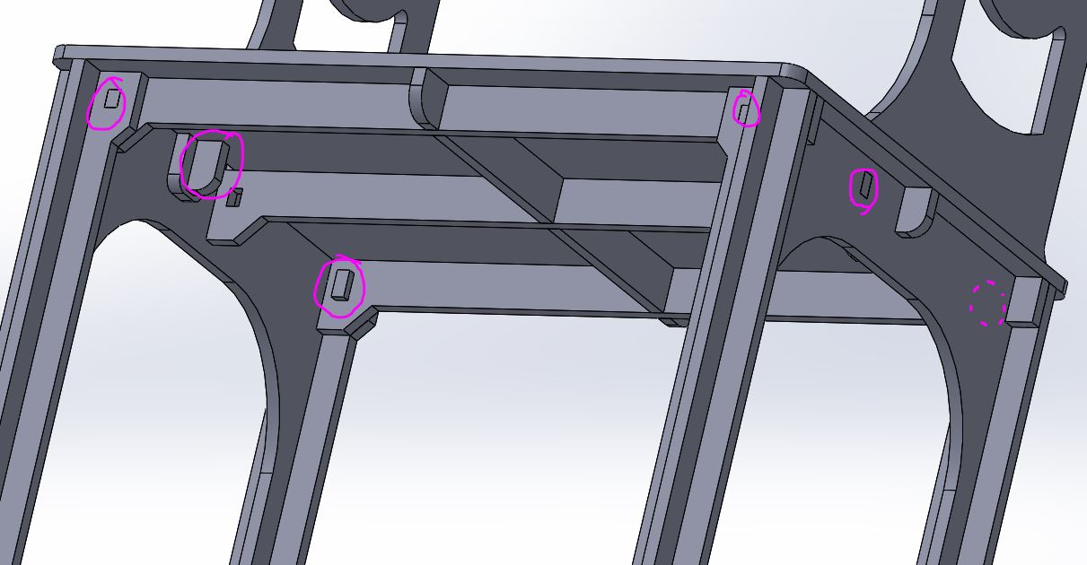
I’m going to use Solidworks to do the design. The wood I am going to use is 1.5 cm plywood. I have used a pressfit = 0 so that the pieces come together tightly together.Also, I have designed pins to fix the different parts.
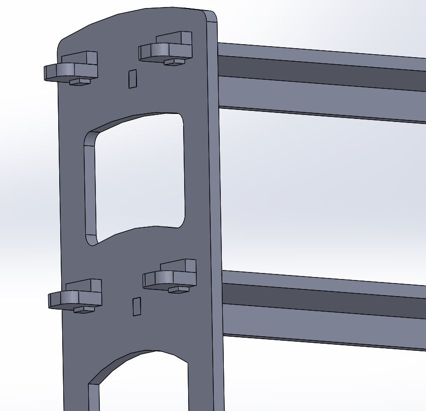
This is the exploded view.

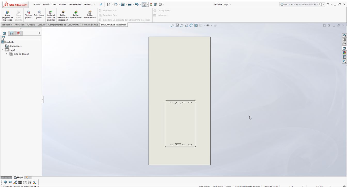
I create a drawing of each piece and save it as a vector file (dxf)
I use Aspire software to generate the gcode. First I import the vector files of the pieces and distribute them in the space of the board. The boards measure 1220x2500x15 mm. I am going to need to use 2 boards. This is the first board.
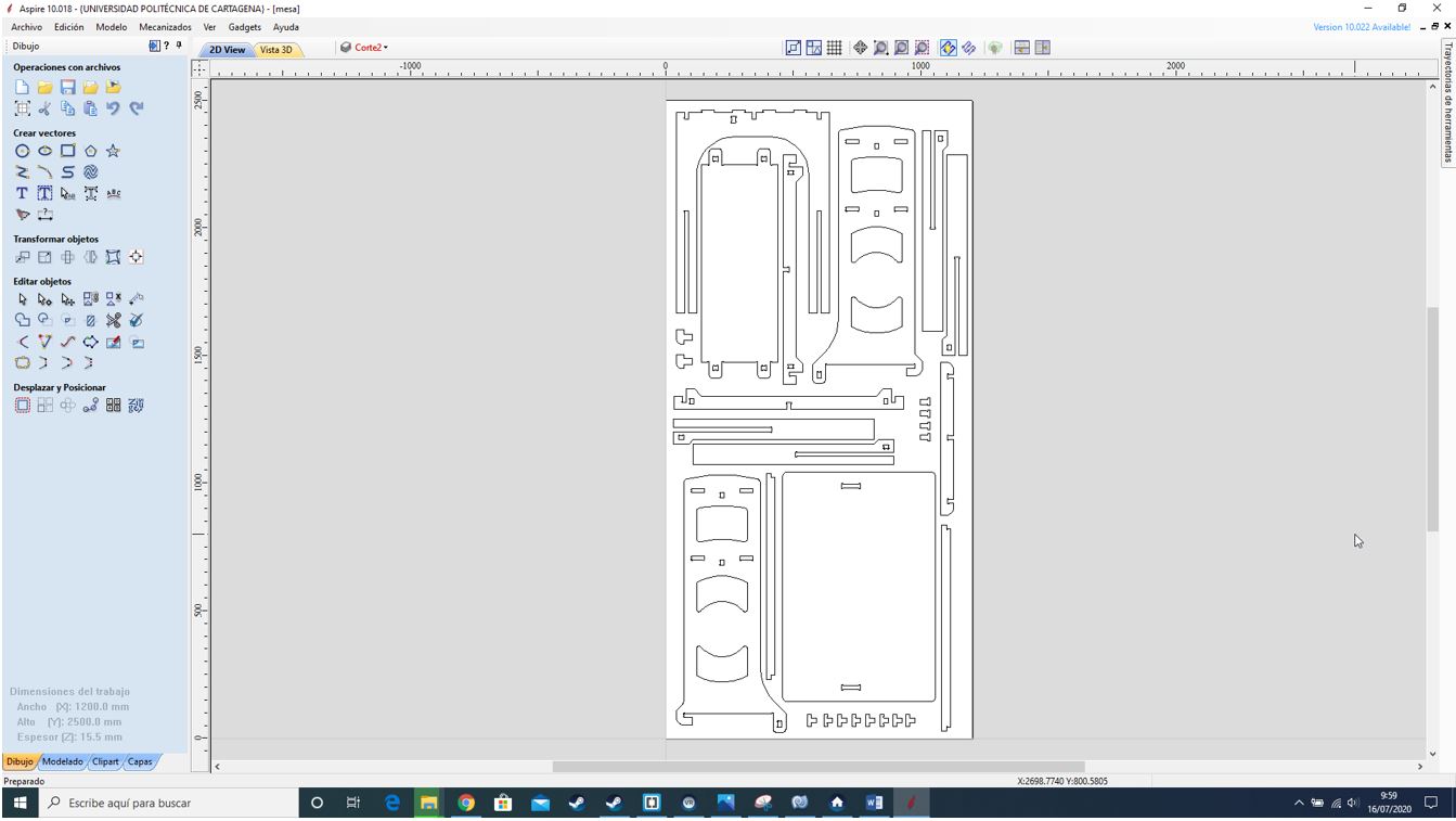
This is the second board.

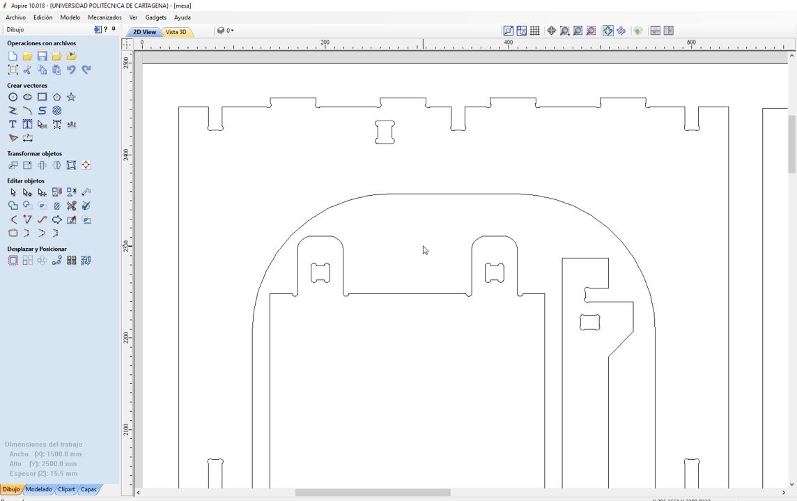
Next I generate chamfers (T or dog-bones) in the corners where the mill must enter.
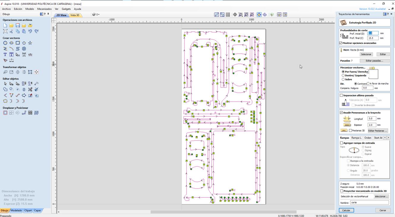
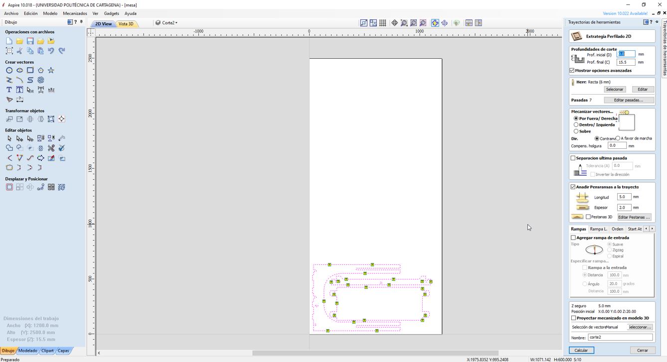
Now I generate the cut operation for both boards.
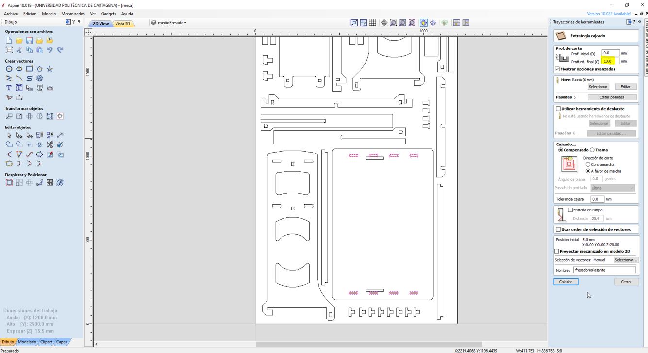
I also generate the operation for the non-through slots of the table.
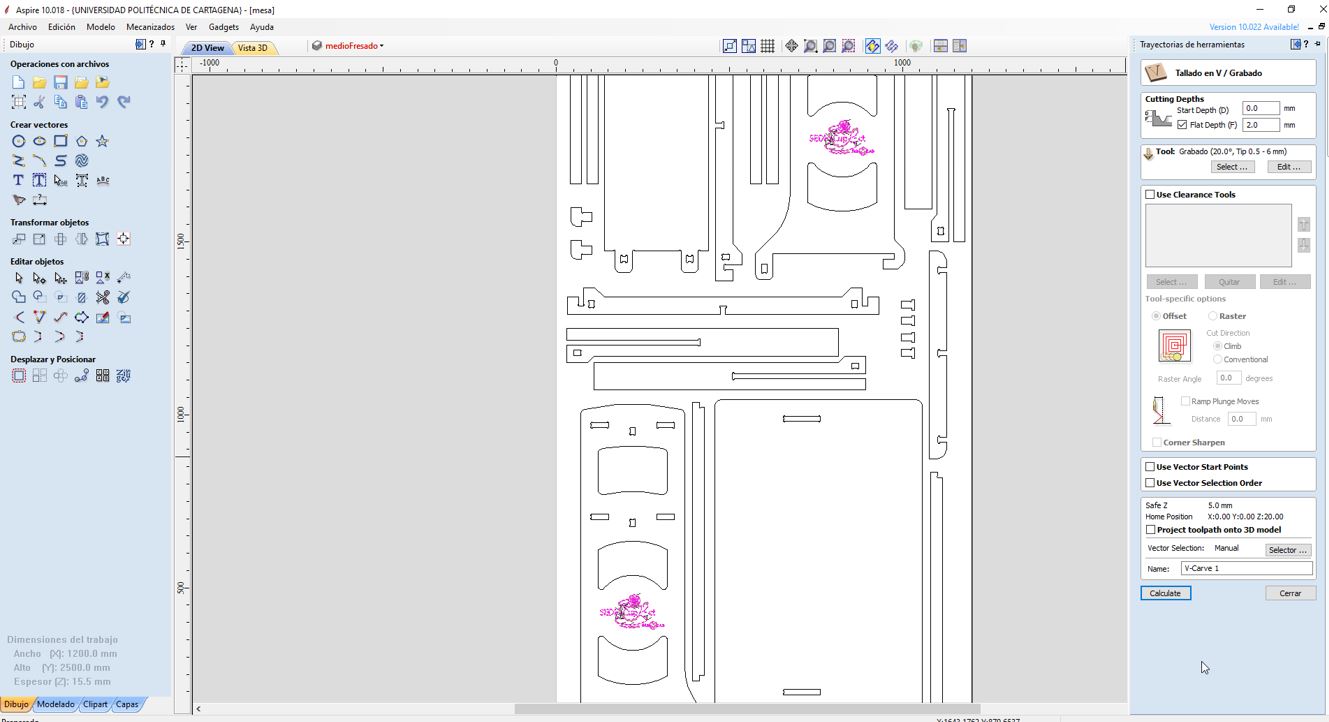
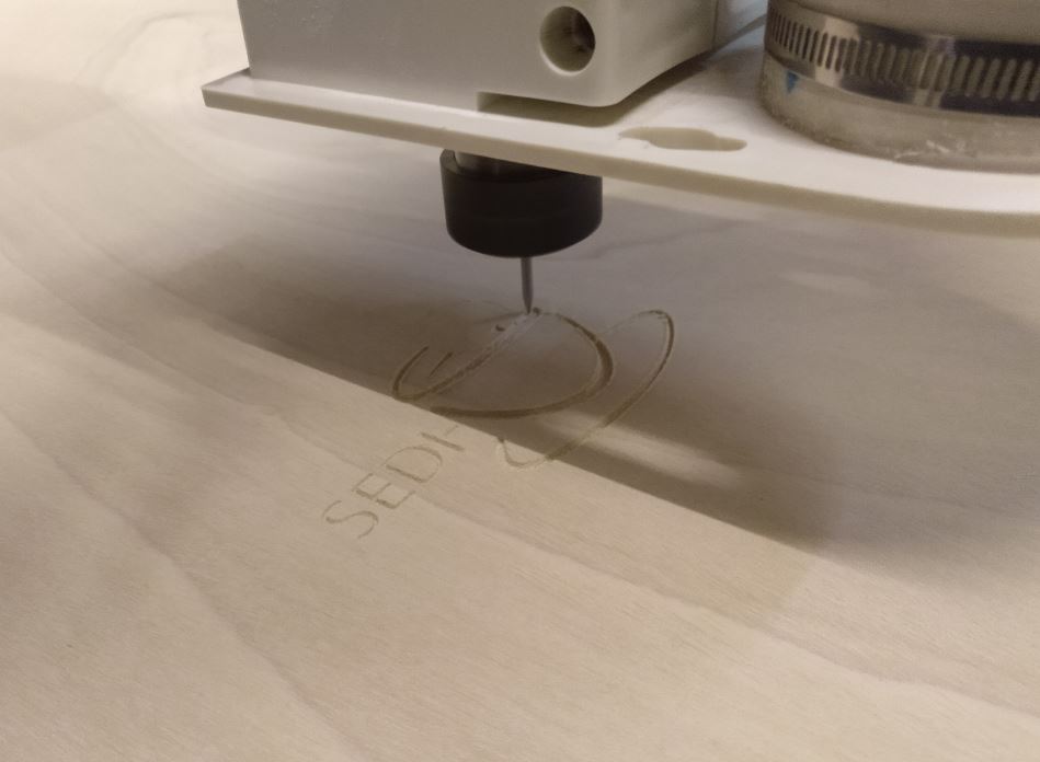
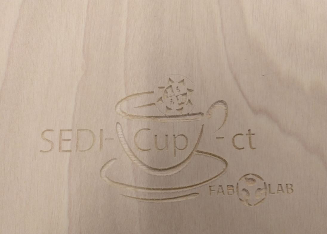
And finally, I generate the engraving operation.
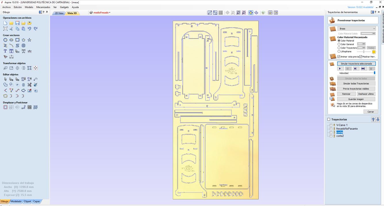
Below you can see the simulation of all operations.
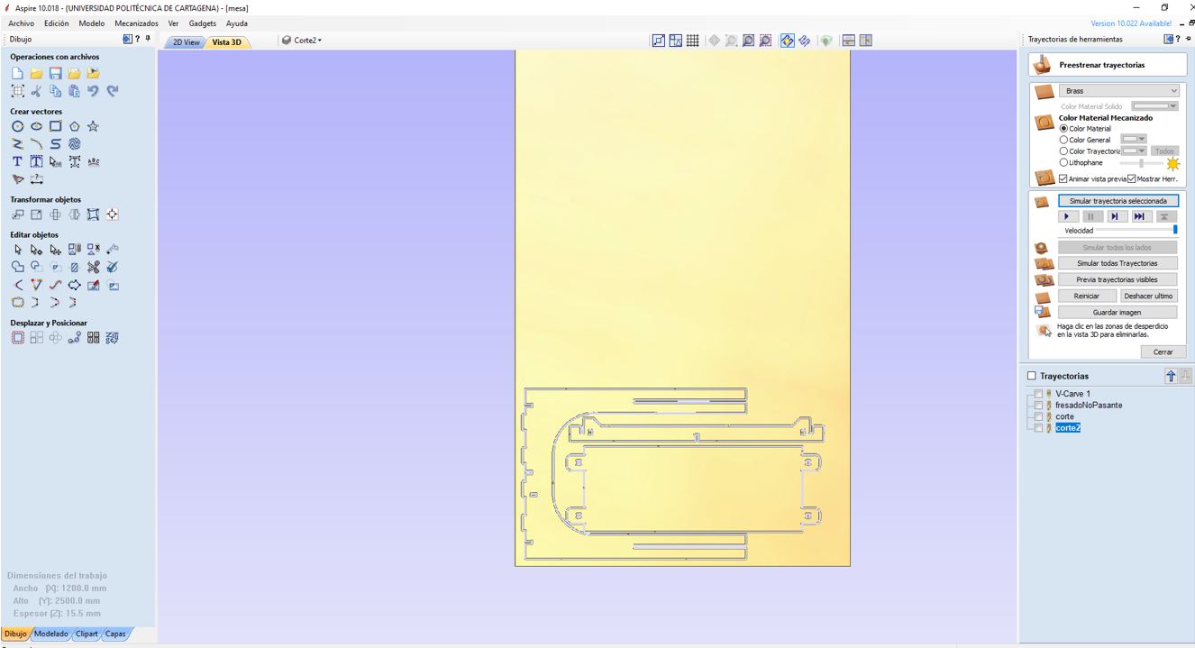
I insert the operations gcodes in the CNC Barcenas milling machine SW1325 and start the engraving operation.
And continued with the cutting operation. I forgot to configure the zero of the z axis and although I stopped it when I realized I had already milled some part. But since the defect only affects aesthetics, I continued with the same board.
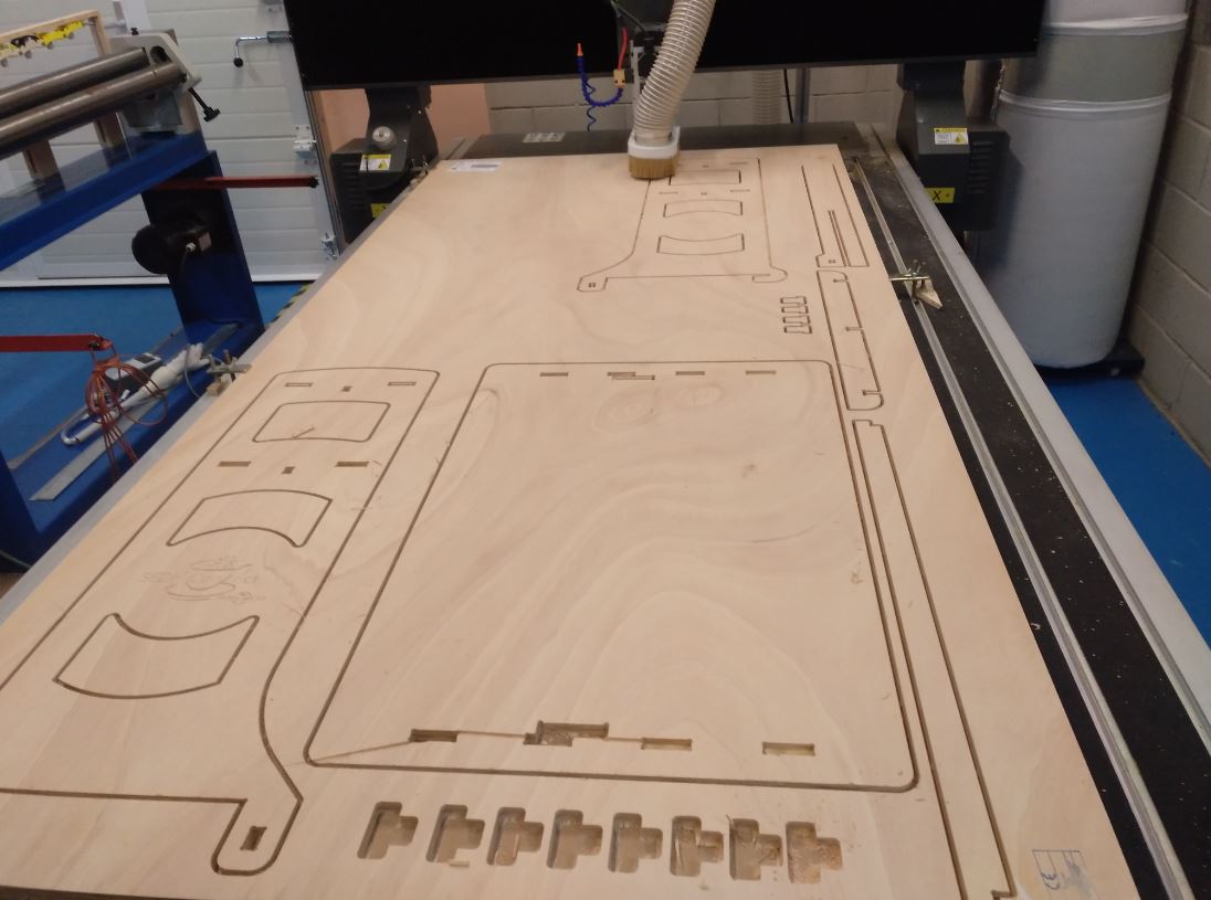
Once all the parts have been cut, I sand the edges to remove chips and start to assemble the table with the help of a hammer.
This is the result.
