7. Electronics design
-
Group assignmet:
- Use the test equipment in your lab to observe the operation of a microcontroller circuit board.
-
Individual assigments:
-
Redraw an echo hello-world board, add (at least) a button and LED (with current-limiting resistor).
-
Check the design rules, make it, and test it.
-
Extra credit: simulate its operation.
-
7.1. Group assignment
The Group Assignment page is at the following link.
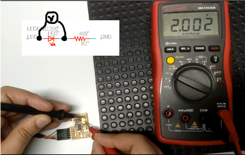
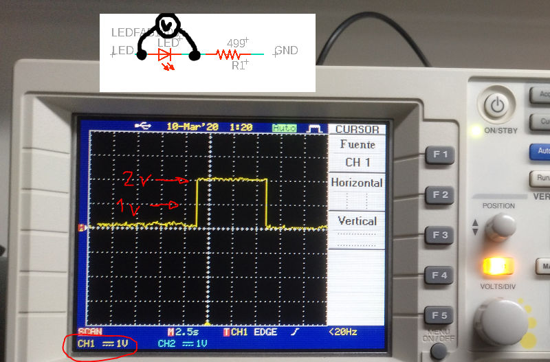
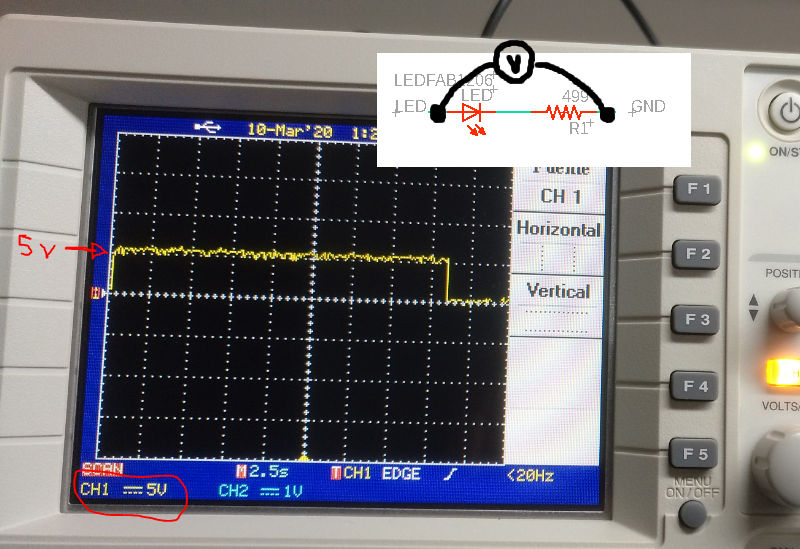
We have used a multimeter and an oscilloscope to measure the voltage in the elements of a hello board. Previously we have loaded the blink program which makes the board led flash. To measure the voltage drop of a component, the tool with which we are going to measure it must be placed parallel to it.
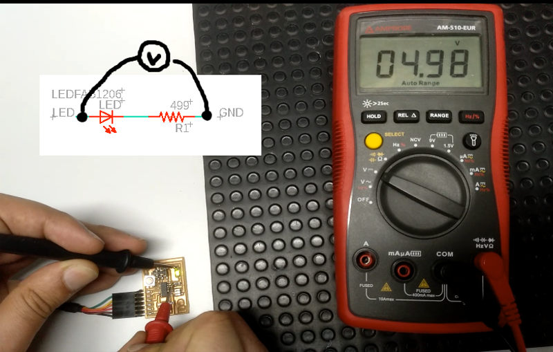
We select the option to measure DC voltage. And we measure the voltage drop in the LED and also in the resistance that is connected in series with the LED. The sum of both must be equal to 5v (voltage of the output pins of the microcontroller).
- Multimeter
- Oscilloscope
-
Results
V (led) = 2v
V (led + R) = 5v
V(R) = 3v
7.2. Individual assignments
I used the Eagle software to draw my echo hello-world board. Follow the tutorial for Eagle.
The steps have been:
-
Download the component library and the design rules of FabLab. LINK
-
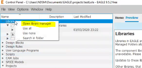
Load them into Eagle and activate the library. Right-clicking on “Libraries” and “Open library manager”.
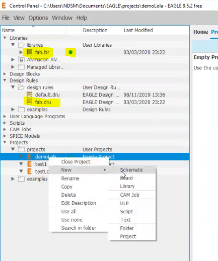
NOTE: If after importing the lbr file it does not appear, it happened to me, try to directly paste the file into the directory where Eagle saves the libraries. In my case in “…\ Documents \ EAGLE \ libraries” and the design rules file in “…\ Documents \ EAGLE \ design rules”.
- Create a new project and within this we create a new Schematic file.
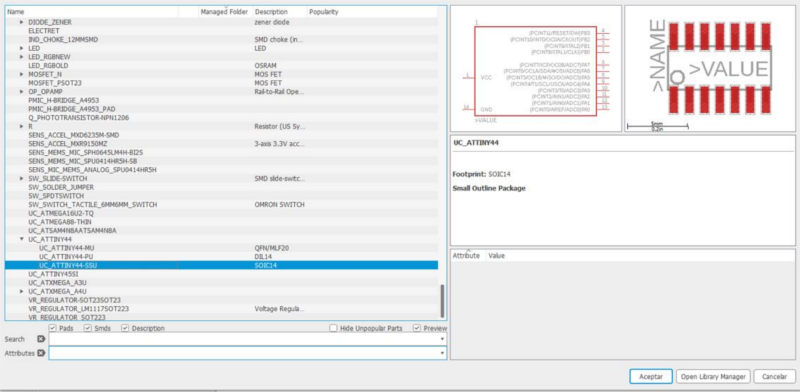
- Insert the circuit components found in the Fab library and connect them with cables or labels.
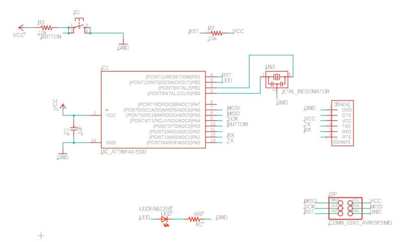
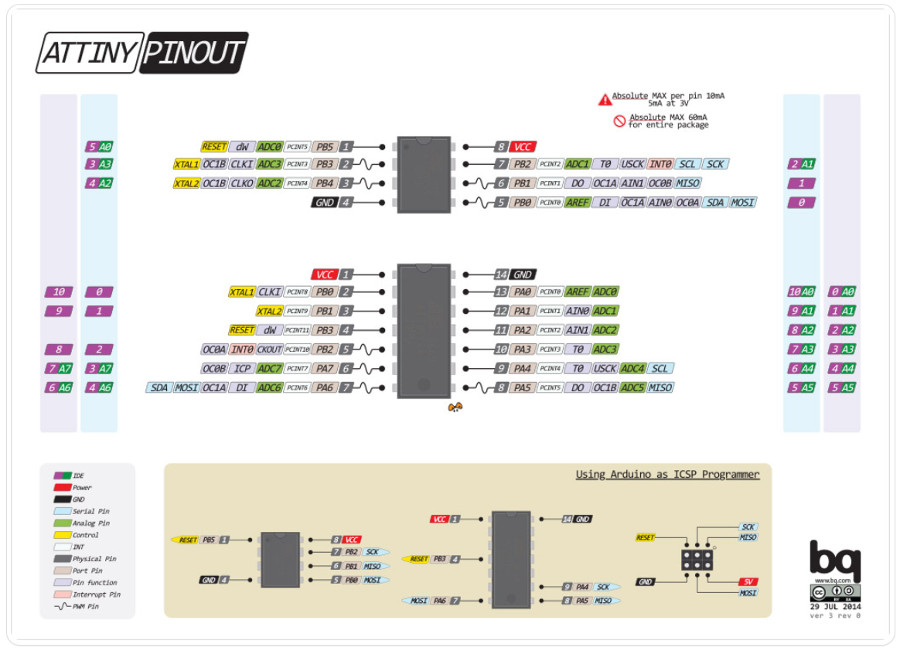
Look at the text next to each pin of the microcontroller to know where to connect the special components:
- Resonator to the XTAL pins

- ISP connector to the MOSI, MISO, SCK and RST pins

- FTDI connector to TX and RX pins
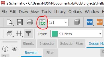
- Once the scheme is finished, go to board mode by pressing the “SCH / BRD” button and place the components on the board and draw the clues.
NOTE: Before drawing the tracks, load the design rules so that the tracks are created with the appropriate configuration. I didn’t do it until I had drawn everything and I had to edit the thickness of the tracks one by one.
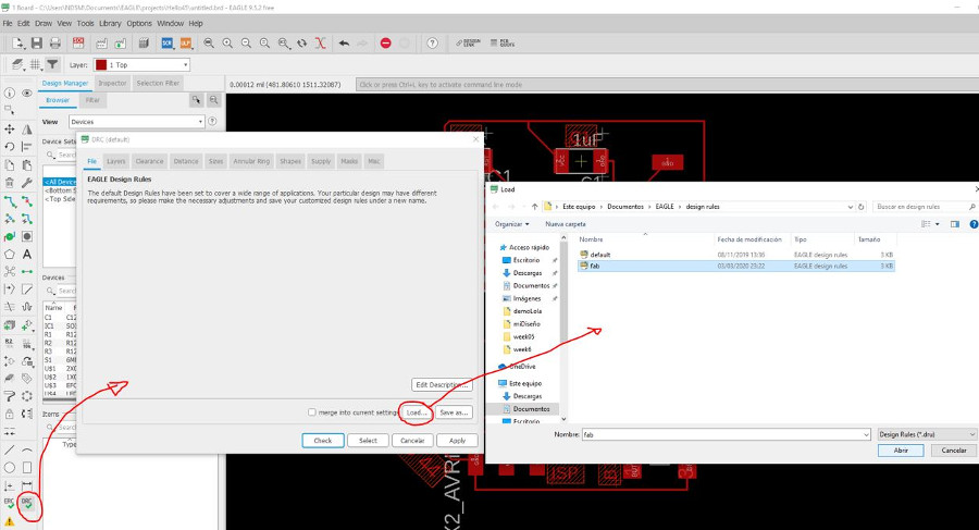
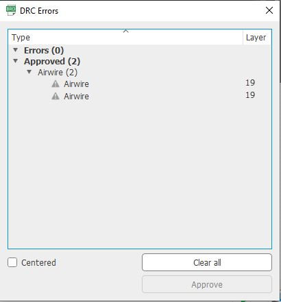
- After designing our board we need to check that the endmill we are using (1/64 usually) is able to go between all the traces so the machine is able to cut successfully the board. For that we are going to use Design Rules Check (script) that will check that there is enought space everywhere.
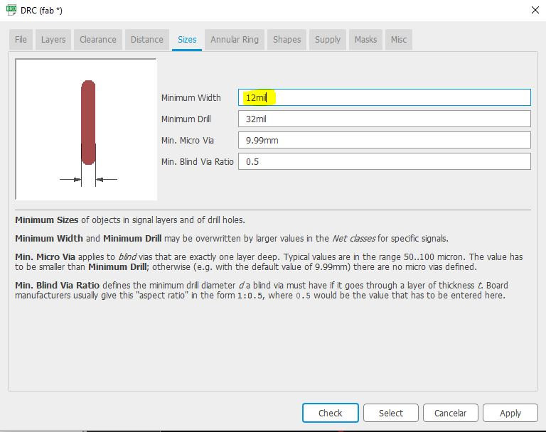
NOTE: In the design rules I loaded the minimum track width was 10mil. I changed it to 12mil based on the characterization of my milling machine to avoid any track breaking when milling. Although seeing the result, it should have gone up to 16 thousand.
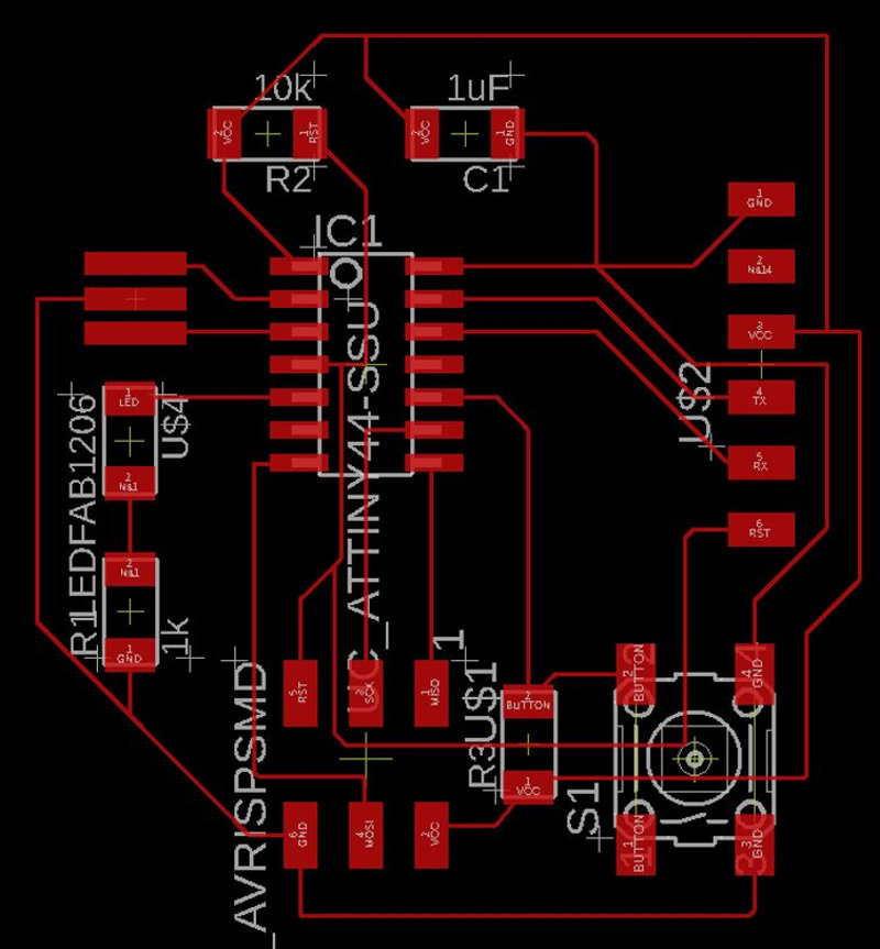
The 2 errors that appear are due to the fact that I have not drawn the clues that connect the button terminals, but I approve them since they are connected internally.
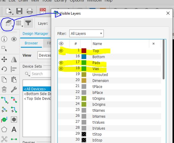
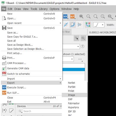
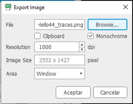
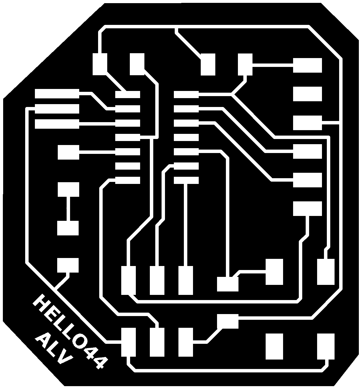
- Finally export the image to mill the board. First leave only the layers of the tracks active.
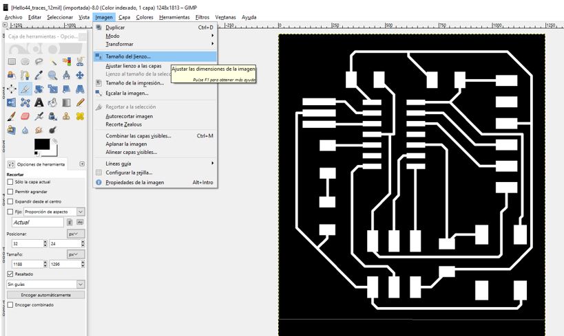
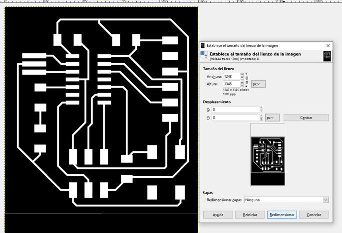
- Open the image in GIMP to edit it and adjust the size and shape of the plate.
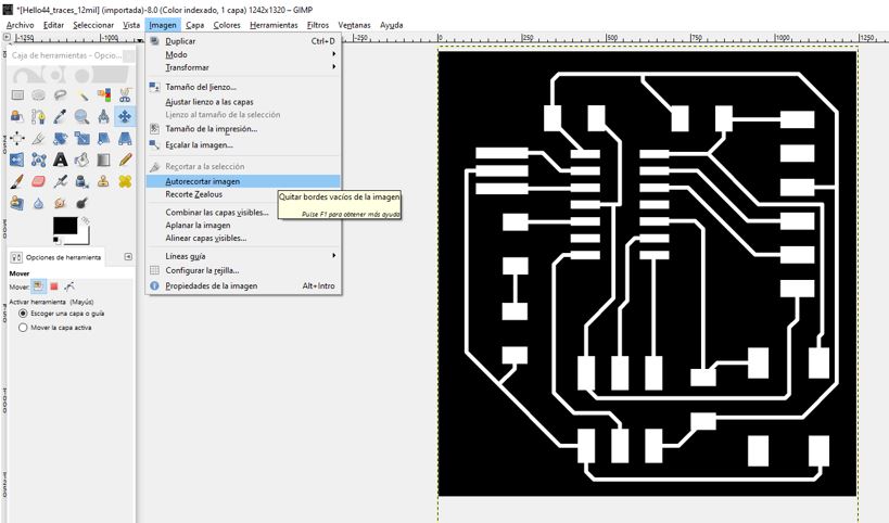
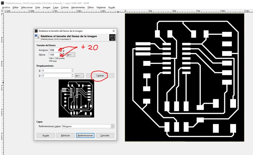
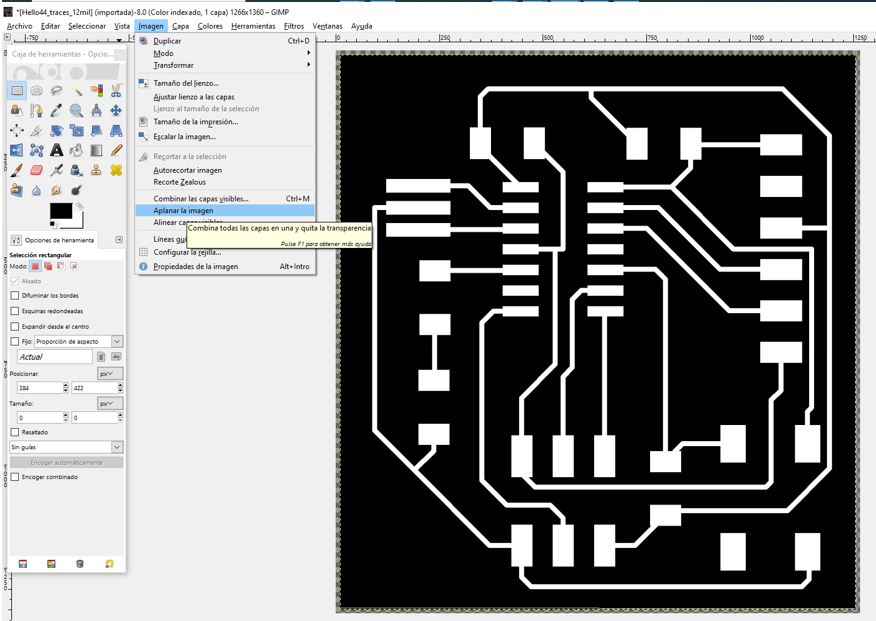
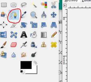
So, I draw the outer shape using the “trace routes” tool

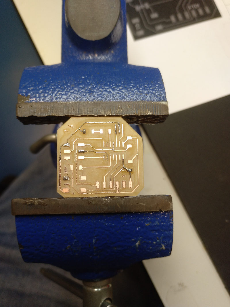
- Milling the board. I have used the CUT2D software with my Stepcraft 420 milling machine.
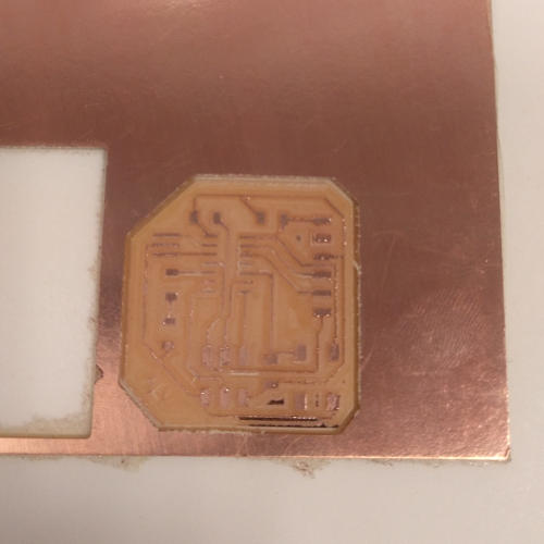
NOTE: I had to reinforce some tracks with tin and repair a broken track with the help of a wire rope. He should have increased the thickness of the tracks to 16mil.
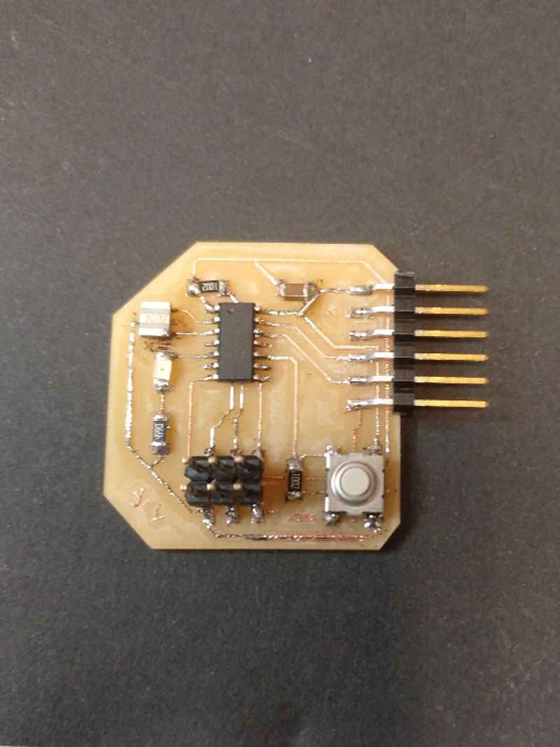
- Weld all components with the help of a little Flux.
-Program the board. Program the board using the programmer that we did in another week and the Arduino IDE software.
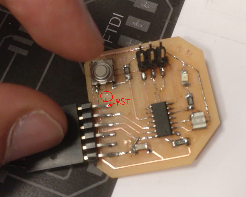
NOTE: It gives me an error when trying to upload the code. And after checking the connections I realize my mistake. It turns out that when I drew the circuit in EAGLE I also attached the RST pin of the FTDI connector to the RST pin of the microcontroller. That FTDI pin gives a 5V signal continuously, proving that the microcontroller was always resetting. I cut that track and solve it.
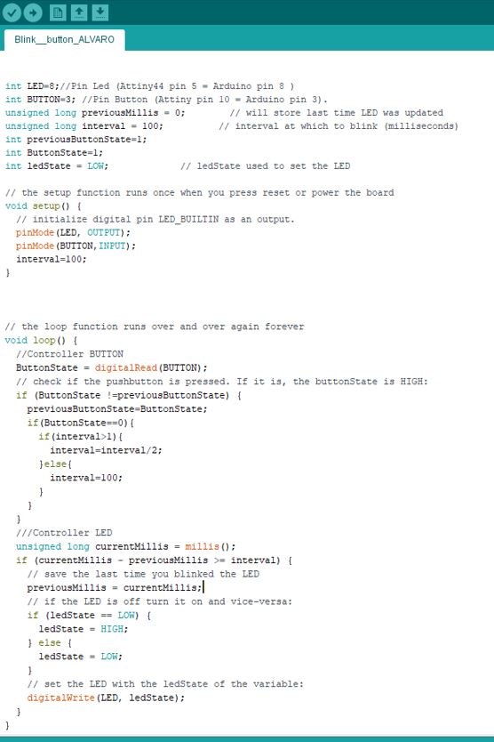
I have made a code in which I use the button and the LED. To know what pins I used in the code I use this scheme:
The LED starts blinking at a slow pace, and each time you press the button the rate changes to twice as fast. And if I continue pressing it returns to the initial rhythm.
7.3. My files
- EAGLE file:
- Board PNG files:
- Arduino Code: