5. Electronics production
Due 2024/02/20
Conceive
- This week we focus on how to build electronic circuits.
- Machining circuits in printed-circuit board material is the opposite of creating a street-racing circuit since one removes material from the terrain (substrate) instead adding to it.

How to use this document
Please refer to instructions in the week02 weblog entry
- Create this box using the Admonition extension
Assignments
Learning outcomes
| To do | Done |
|---|---|
| Describe the process of tool-path generation, milling, stuffing, de-bugging and programming. | No |
| Demonstrate correct workflows and identify areas for improvement if required. | No |
Checklist questions
| Have you? | Done |
|---|---|
| Linked to the group assignment page? | Yes |
| Documented how you made (mill, stuff, solder) the board? | No |
| Documented that your board is functional? | No |
| Explained any problems and how you fixed them? | No |
| Included your source code files? | No |
| Included hero shots of your board? | No |
Context
- Syllabus FAW05
- Assessment FAW05
- Tutorial FAW05
- Video FAW05
- Review FAW05
- FabAcademy 2021 Documents
- FabAcademy Mattermost Chat Page
- FabAcademy Evaluation Page This site requires a fablab.io account to login
- FabAcademy Home Page
- FabLabs Home Page
Comprehend
- PCB machining happens when end mills remove copper chips from PCB boards unlike the low to no kerf-cutting done by lasers and vinyl cutters.
- We will be making embedded systems using microcontrollers and surface-mounted devices, SMD.
- Initially, we will use AVR-compatible microcontrollers.
- AVR controllers are compatible with the Arduino development environment.
Wednesday
- Get familiar with the tools for this week.
- Understand endmills.
- Familiarize myself with the Roland DG SRM-20.
- Complete group assignment.
- Learn how to locate electronic components in the lab.
- Access Mods for tool-path creation.
- Locate or install KiCAD and Fusion 360 software for EDA work.
Understand end mills
- Select the correct end mill.
- Companies such as Harvey Tool Company offer a mind-numbing selection of end-mill options.
- Firstly, they offer five tip options: square, ball, corner radius, corner chamfer, tapered. Each tip offers unique advantages.
- Square offers a clean, level cut across the contact surface
- Ball tips create better layer transitions for mold-making.
- Corner radii make mills more durable
- Corner chamfer reduces tool wear and distributes heat more evenly across tool face.
- Taper tips allow deep-cavity machining
- Secondly, many tips come in different lengths
- Stub
- Standard
- Long reach
- Additionally, Harvey offers two notable tip coatings
- Aluminum-titanium nitride which improves hardness and temperature resistance. It is good for ferrous materials
- Amorphous diamand significantly improves tip hardness relative to uncoated mills. It is not temperature resistant. It can be used to mill non-ferrous materials such as carbon fiber, plastics, and brass.
- Firstly, they offer five tip options: square, ball, corner radius, corner chamfer, tapered. Each tip offers unique advantages.
- Other micro end mill characteristics
- Flute count
- Fewer flutes means larger flute valleys and better material removal
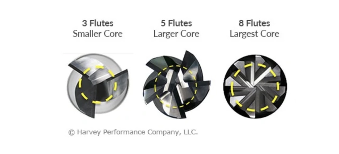
- More flutes means larger tool core, smaller valleys, and better tool strength.

- Rule of thumb is use two-flute tools for machining non-ferrous materials and machining that requires significant material removal.
- Use four-flute tools machining ferrous material and longer tool life.
- Fewer flutes means larger flute valleys and better material removal
- Tool diameter requirements
- Resolution required by the design
- Speed of the cut
- Quality of the cut
- Conical or V-bit tip
- Used for engraving.
- Used by some to machine printed circuit boards
- By milling at different depths, one bit can machine traces and interiors.
- Flute count
- Companies such as Harvey Tool Company offer a mind-numbing selection of end-mill options.
Get familiar with SRM 20
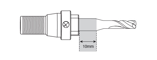
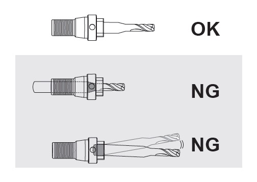
- Secure end mill to the machine.
- Insert the end mill into the collet leaving approximately 10mm or 0.5in of the shank exposed.

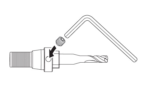
- (SRM-20) Tighten the set screw of the collet to secure the end mill.
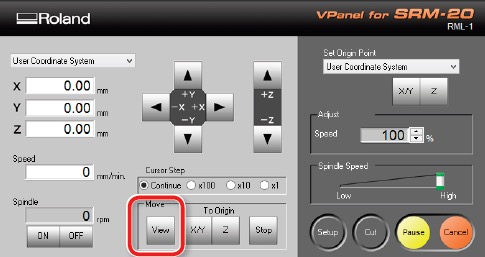
- (SRM-20) In VPanel, click view to bring the spindle forward send the milling table to the back of the machine.
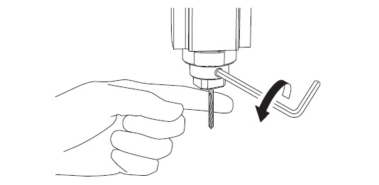
- (SRM-20) Thread the collet into the spindle by hand.
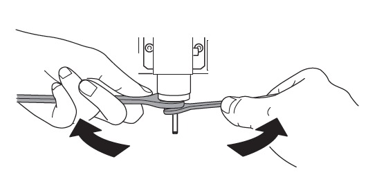
- Use spanners to fully secure the collet to the machine.
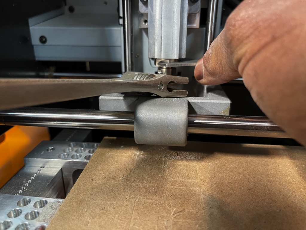
- Insert the end mill into the collet leaving approximately 10mm or 0.5in of the shank exposed.
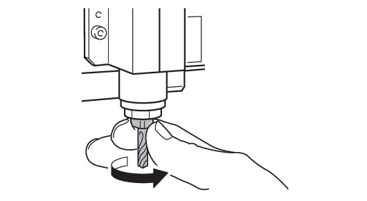
- Zero the z height of the end mill
- Once the tool is in the machine, jog the milling table somewhere below the end mill.
- Move the heighth of the spindle approximately 5mm above the milling surface.
- While holding the end mill in place with a finger, loosen the set screww of the collet.
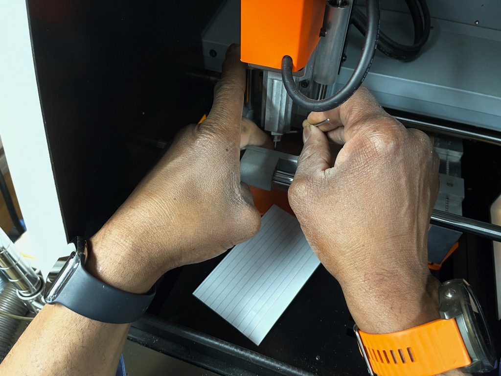
- Allow the end mill to tap the surface and come to rest.
- Tighten the set screw.
- The tool should now be close to zero in the z axis. To be sure jog the spindle 0.1mm lower.
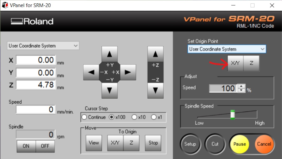
- Set the origin of the z axis of the User Coordinate System.
- Homing
- (SRM-20) Use the jog controls to locate the milling table in desired location.
- Zero the x and y axes of the User Coordinate System.
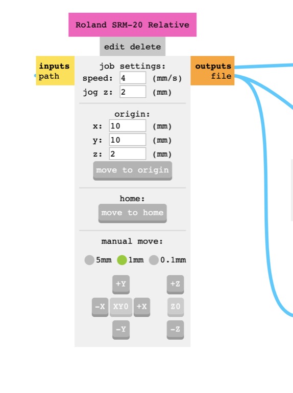
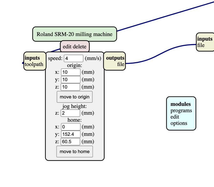
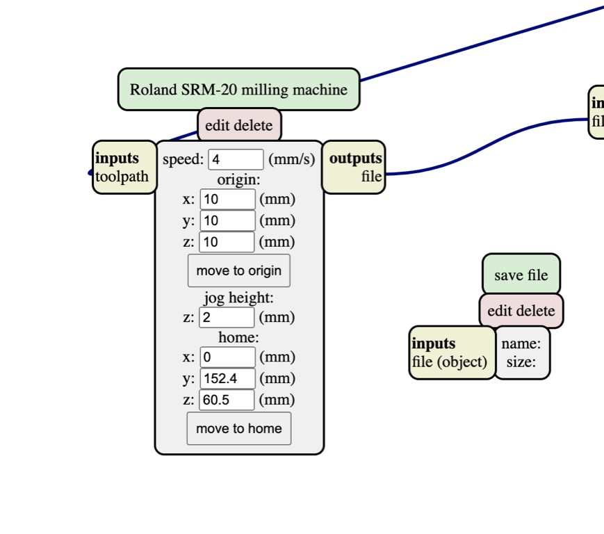
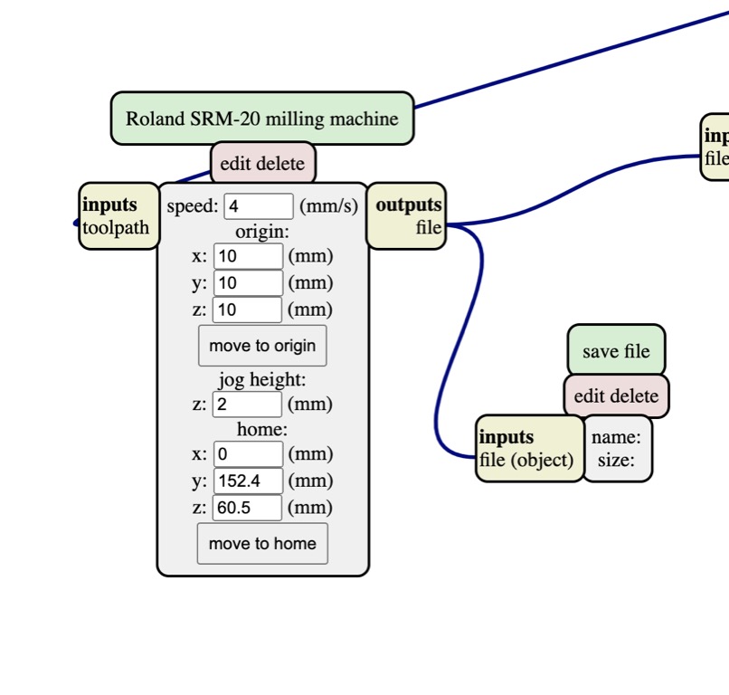
- For SRM-20, I can use Mods Project or Neil’s Mods from the CBA to set feeds, speeds, plunge rate, and depth-of-cut. Both versions use a separate module to save machine code in an RML file.
- For this assignment, I characterized speeds by cutting the line test pattern at 2, 4, and 6mm/s using a 1/64in square and stub end mill with two flutes to determine the maximum speed at which the machine could maintain 0.001in resolution.
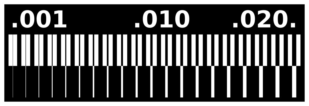
- 2mm/s
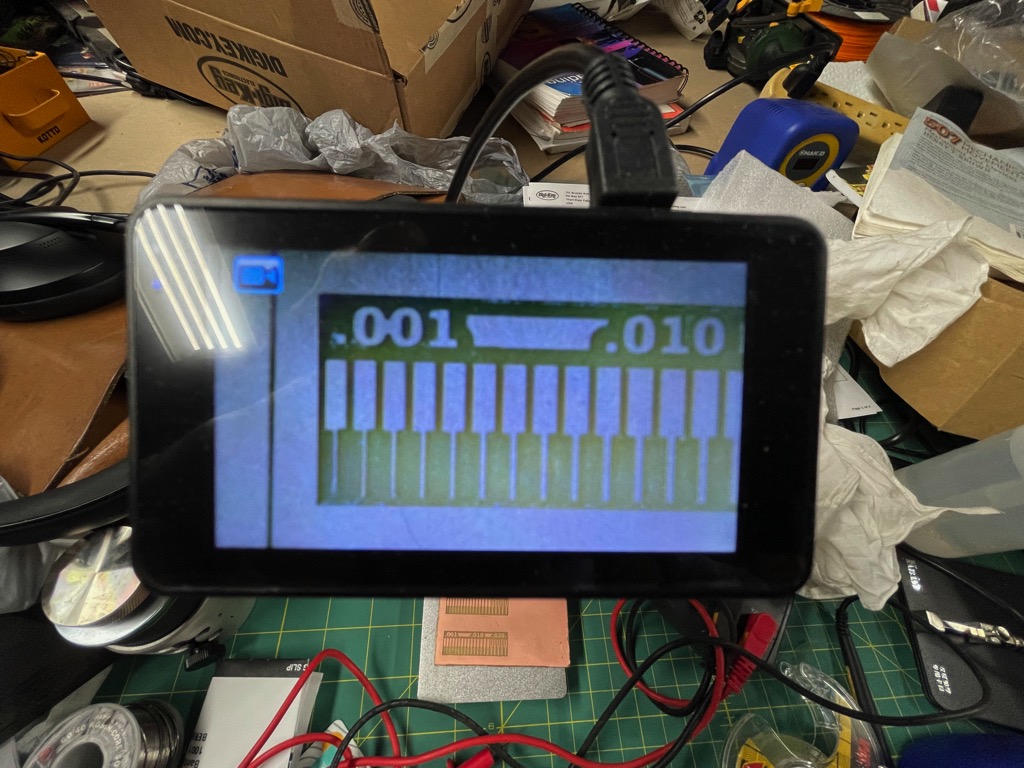
- 4mm/s
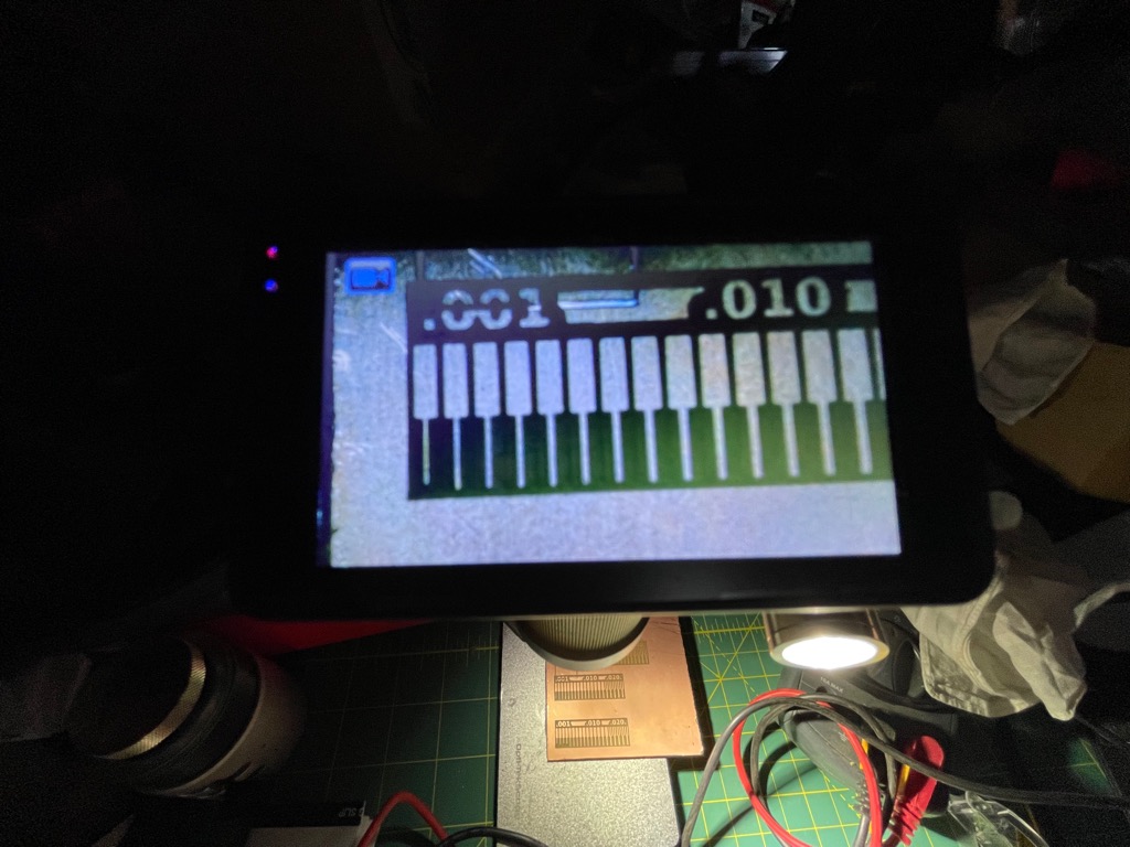
- 6mm/s
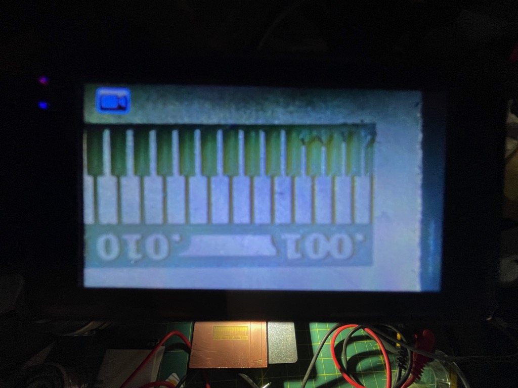
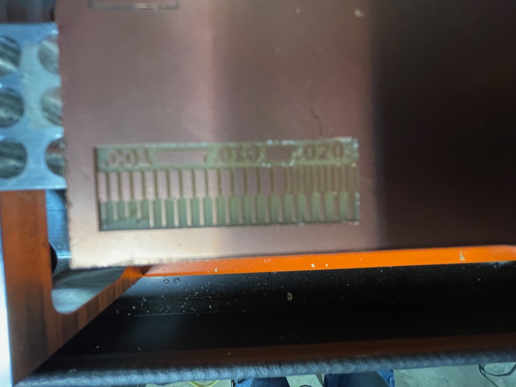
- 6mm/s experienced tearing at 0.004in and below; neither 4mm/s nor 2mm/s experienced tearing.
- 6mm/s machines about three times as fast as 2mm/s. I can probably run the machine at 5mm/s and maintain resolution down to 1/1000 in for traces.
- For this assignment, I characterized speeds by cutting the line test pattern at 2, 4, and 6mm/s using a 1/64in square and stub end mill with two flutes to determine the maximum speed at which the machine could maintain 0.001in resolution.
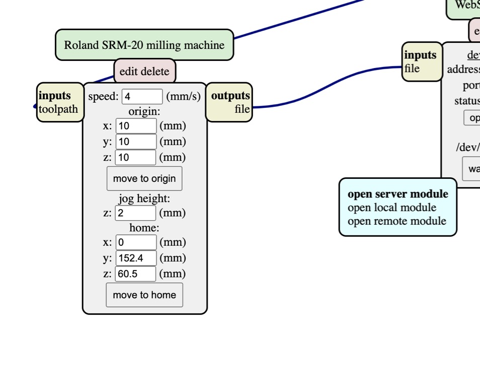
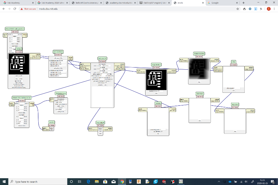
Access Mods
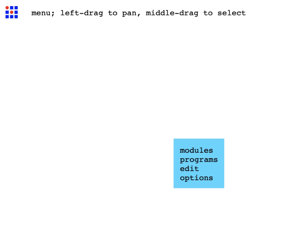
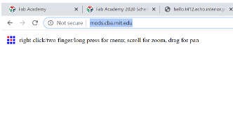
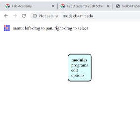
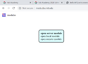
- Initially, I used the Mods Project Mods to generate the RML files. From the modsproject.org landing page, “right clck” anywhere on the page to launch the Mods menu.
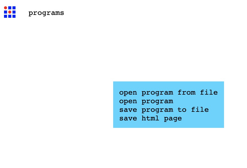
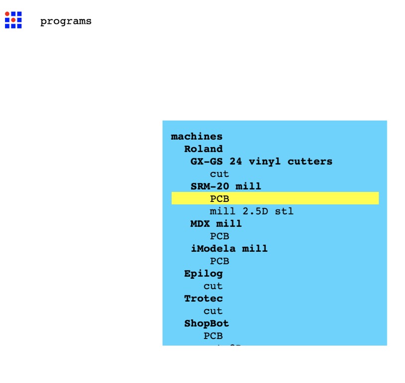
- “Left click” programs to select the programs sub-menu.
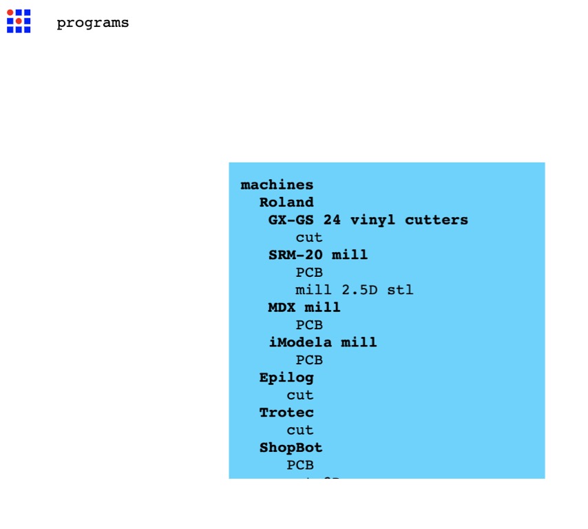
- Scroll down the sub-menu to reveal the SRM-20 mill in the list.
- Select PCB to launch the milling machine program.
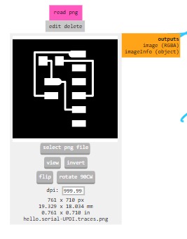
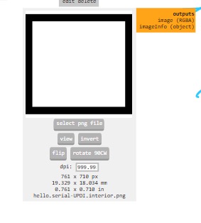
- The program accepts either SVG or PNG formats as input files.
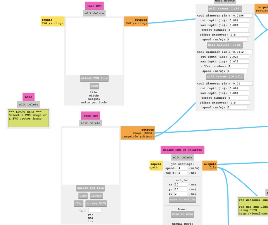
-
Warning
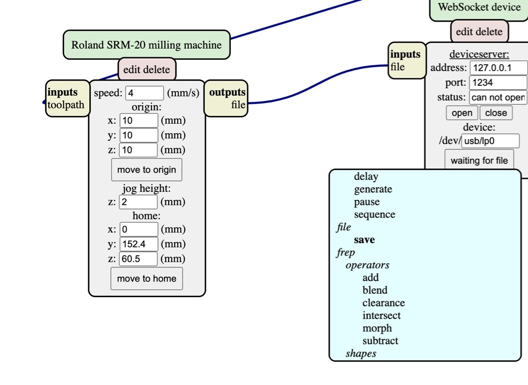
Please remember to attach the input of the save file module to the output of the SRM-20 module in order to save the RML file on your computer.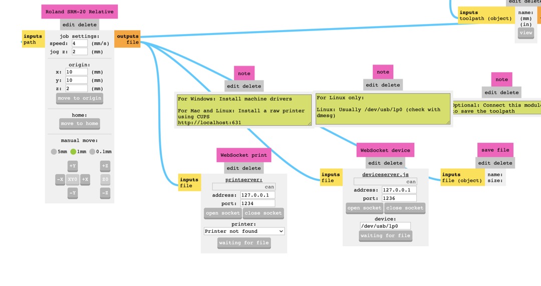
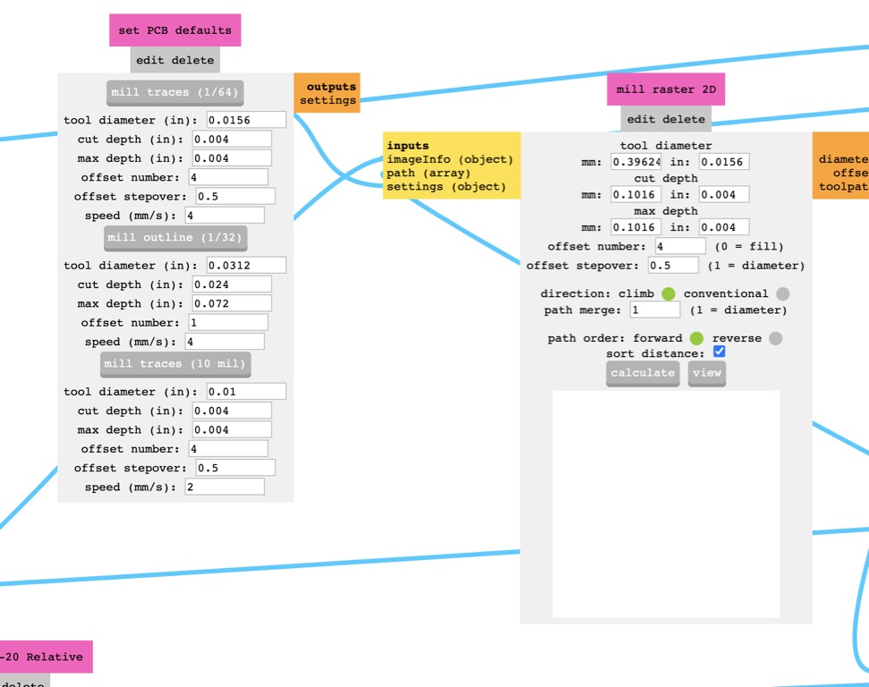
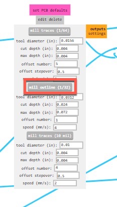
- Use the set PCB defaults module to select the correct machining process of either mill traces or mill outline by clicking the appropriate button.
- In the SRM-20 module, I set the origin to x: 5, y: 5, z: 0. This reduces PCB waste.
- Scroll down the sub-menu to reveal the SRM-20 mill in the list.
- “Left click” programs to select the programs sub-menu.
Thursday
- Choose an in-circuit programmer to make
- Identify and pick components for programmer
- Design dev. board using EDA
- Identify and pick components for dev. board.
In-circuit Programmer
-
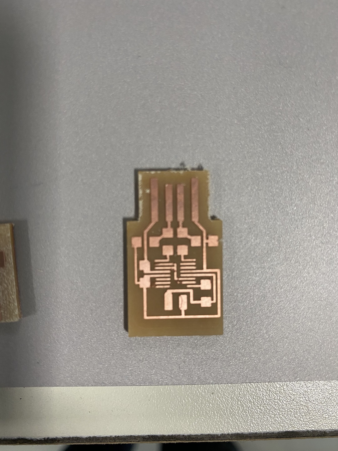
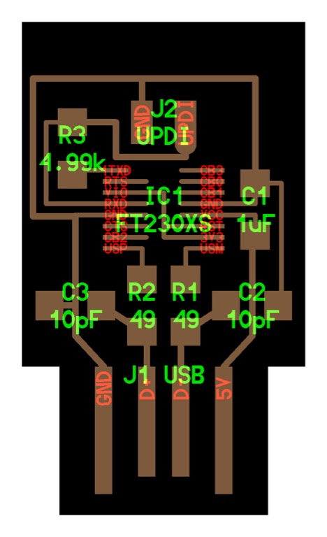
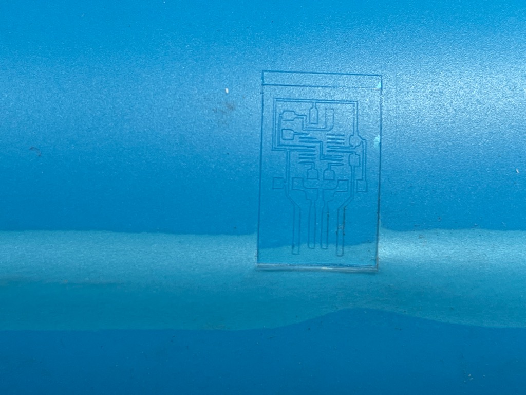
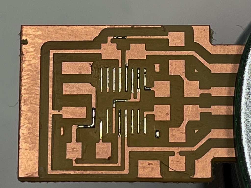
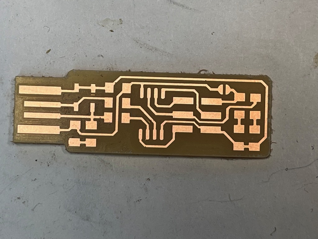
I took the following steps to prepare traces and interior RML files for the hello serial updi circuit: 1. Upload the traces PNG file.
 2. Connect the save file module to the SRM-20 module.
3. Set the origin to x: 5, y: 5, z: 0.
4. Set mill cutting mode to mill traces in the set PCB default module.
2. Connect the save file module to the SRM-20 module.
3. Set the origin to x: 5, y: 5, z: 0.
4. Set mill cutting mode to mill traces in the set PCB default module.
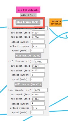 5. Per the line tests done in the calibration section, changed the feed speed from 4 to 5 for the mill traces.
6. Confirm tool diameter in mill raster 2D module
7. Click calculate to create tool paths and RML file.
5. Per the line tests done in the calibration section, changed the feed speed from 4 to 5 for the mill traces.
6. Confirm tool diameter in mill raster 2D module
7. Click calculate to create tool paths and RML file.
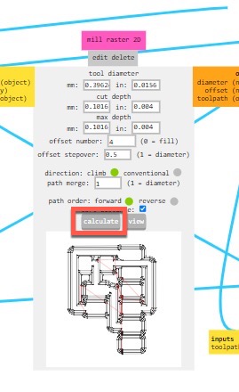 8. Perform similar steps for interior file.
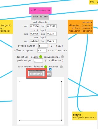 1. The site produced acceptable paths when using 4 as the offset number in the “Mill Raster 2D” module.
 2. !!! failure Mill Raster 2D
The RML file from Mods Project produced unacceptable results when using 0 as the offset number. The depth-of-cut was much deeper than expected each pass.
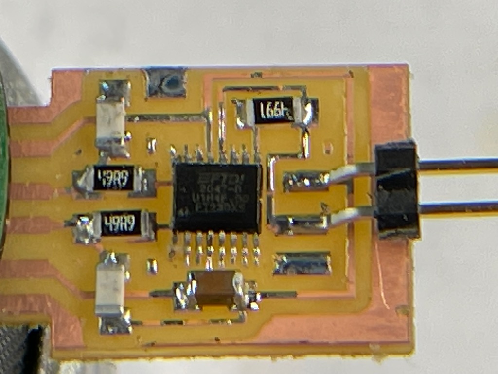
1. I used Neil’s version of Mods instead of Mods Project to create the tool paths with 0 offset number and RML files for FT230 and FTDI boards.
2. The setup is very similar to that of Mods Project
2. !!! failure Mill Raster 2D
The RML file from Mods Project produced unacceptable results when using 0 as the offset number. The depth-of-cut was much deeper than expected each pass.
1. I used Neil’s version of Mods instead of Mods Project to create the tool paths with 0 offset number and RML files for FT230 and FTDI boards.
2. The setup is very similar to that of Mods Project
 3. !!! warning
Please remember to add a “save file” module to the “server” module in Neil’s version of Mods. Click input on the save-file module then click on the output of the SRM-20 module in order create a connection between them. This will enable the RML file to be saved on your computer.
3. !!! warning
Please remember to add a “save file” module to the “server” module in Neil’s version of Mods. Click input on the save-file module then click on the output of the SRM-20 module in order create a connection between them. This will enable the RML file to be saved on your computer.
- Controller-machine interface
-
Warning
While the controller-machine interface step logically follows the computer-controller interface, a user should perfom the machine-material interface step first because the VPanel runs the machine code immediately after a user clicks the output button. This means that material to be milled should already be fixtured to the machine. - Roland software VPanel uses the RML file to run the SRM-20.
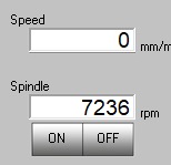
- Left-click the cut button to upload the RML or GCODE file to VPanel.
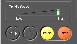
- Select an output file to control the machine from the dialog window that appears.
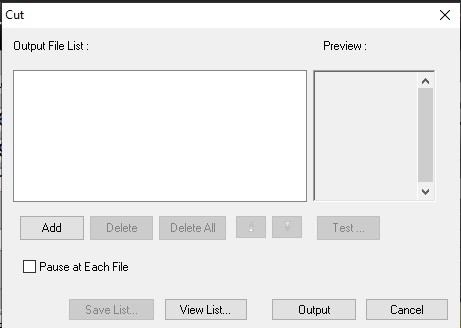
- Click the output button to machine the PCB.
-
Note
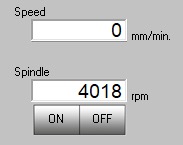
All of the spindles on our desktop mills–SRM-20, MDX-40A, and Bantam Tools PCB mill–run better if the operator slowly increases the speed of the spindle before machining anything. - For the SRM-20, a user must warm the manually. Use the spindle speed slider to reduce the initial speed to low.
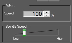
- Click the spindle on button.
-
Warning
The spindle will make noise, spin more slowly, and with greater variation in speed before it is warm. Wait for at least one minute or until the “chatter” stops before increasing the speed of the spindle. -
Note
I believe that this does not adversely affect machining quality. I believe that it reduces machine wear.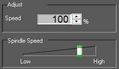
-
- Machine-material interface
- Materials
- Printed circuit board (PCB), type FR1.
- copper outer layer on one side with paper substrate.
- Will mill with out damage to the tool.
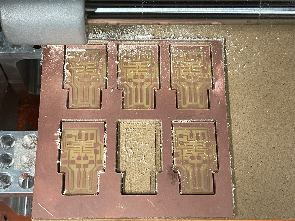
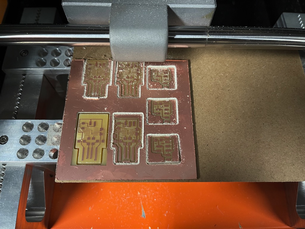
- Sometimes, I quarter a standard board for machining. It can produce six to nine small circuits.
- Fixtures
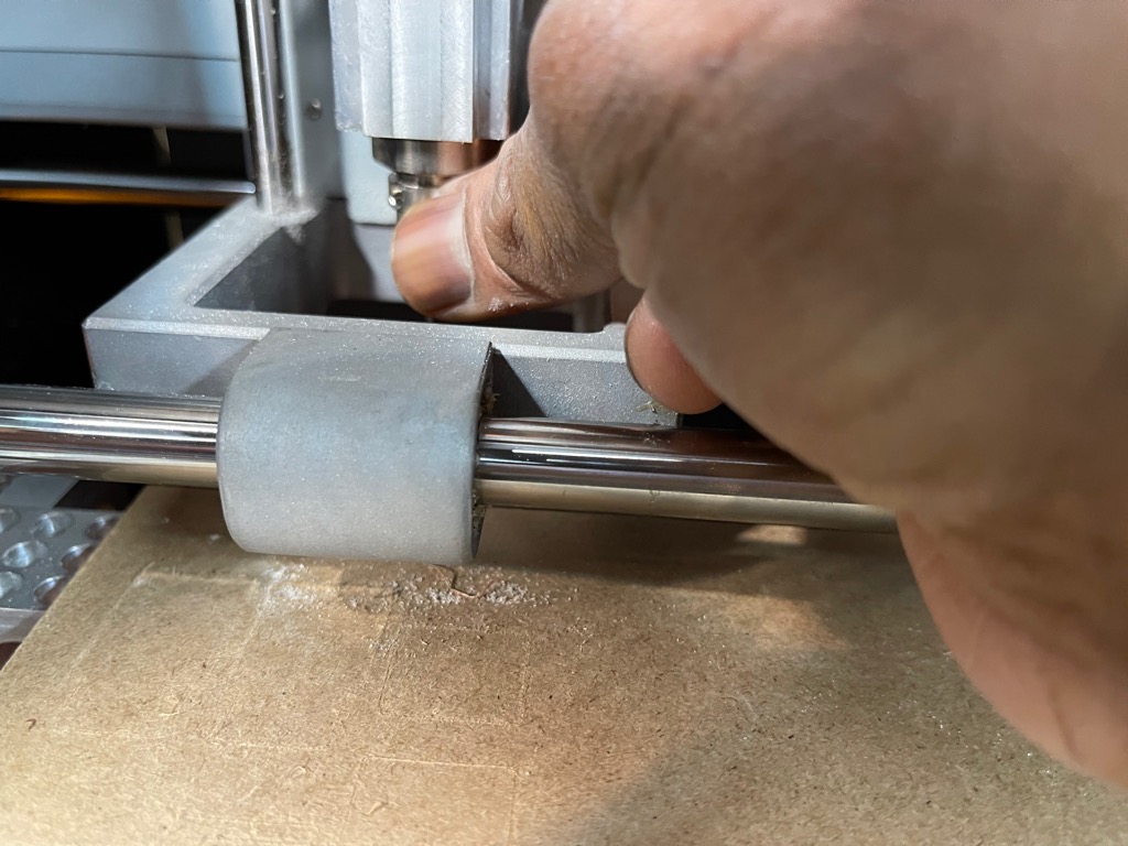
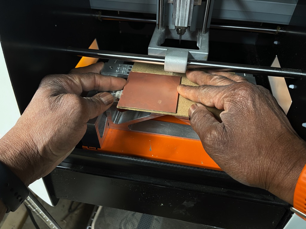
- Attach a blank PCB with paper side up to the aluminum spoil board of SRM-20 using double-sided tape.
- I have seen people apple the tape in differnt patterns.
- I apply it vertically–edge to edge–with no overlap.
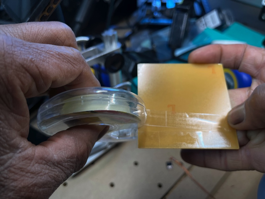
- I press the piece onto the spoilboard of 0.25” MDF in the lower left corner.
- Tools
- Using two mills for pcb production
- Carbi-Universal round end mill
- 220823 0.015” 2FL SQ micro em stub altin s/c micrograin
- 220867 0.031” 2FL SQ micro em stub altin s/c micrograin
- I first install the 0.015” end mill to the machine per the instructions in calibrate
-
Warning
This reduces the risk of damaging the machine, the mill, or the PCB before zeroing the z axis.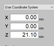
- Set x-y origin point in the lower left corner of the copper per the instructions above.
. This may yield unsatifactory results if the corner is not rigid.
- Use the above approach to zero z.
- Materials
- Stuff board
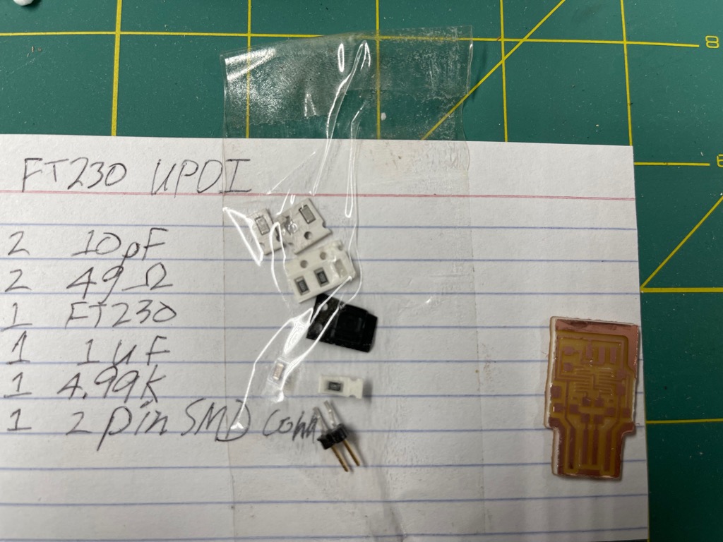
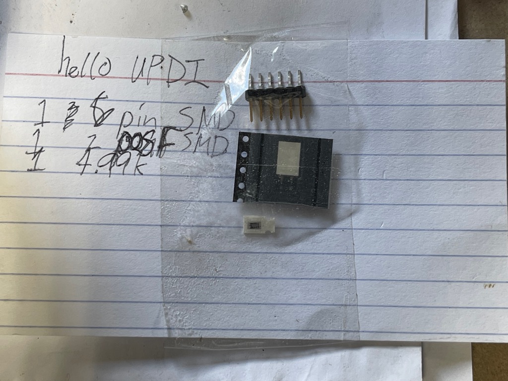
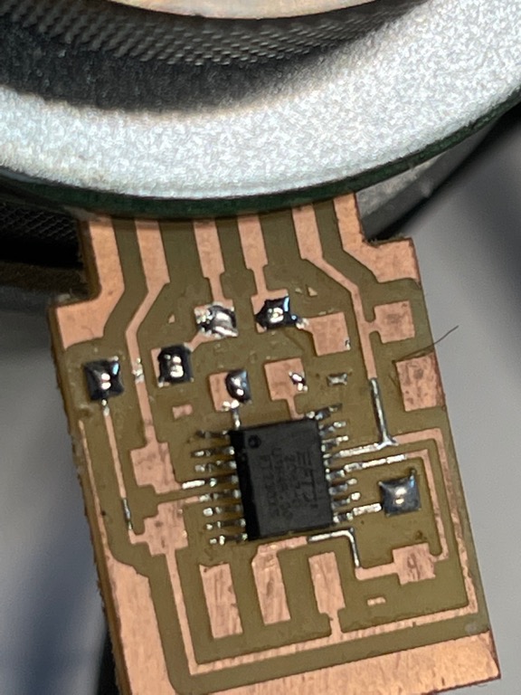
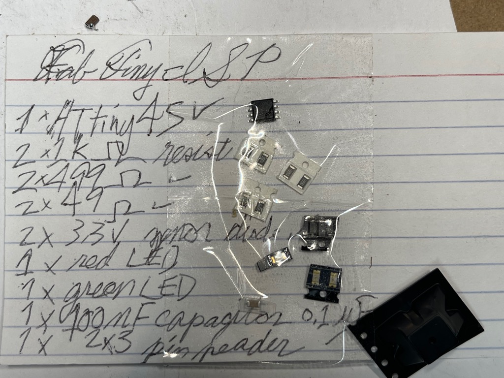
- Collect components for the FT230 and hello UPDI boards.
- Deburr board if necessary.
- Clean board with alcohol to remove oil and dirt.
- Choose your soldering approach:
- Soldering iron
- Stencil with
- Rework
- Reflow
- Rework
- Soldering iron
- When using a soldering iron, place board in your preferred fixture.
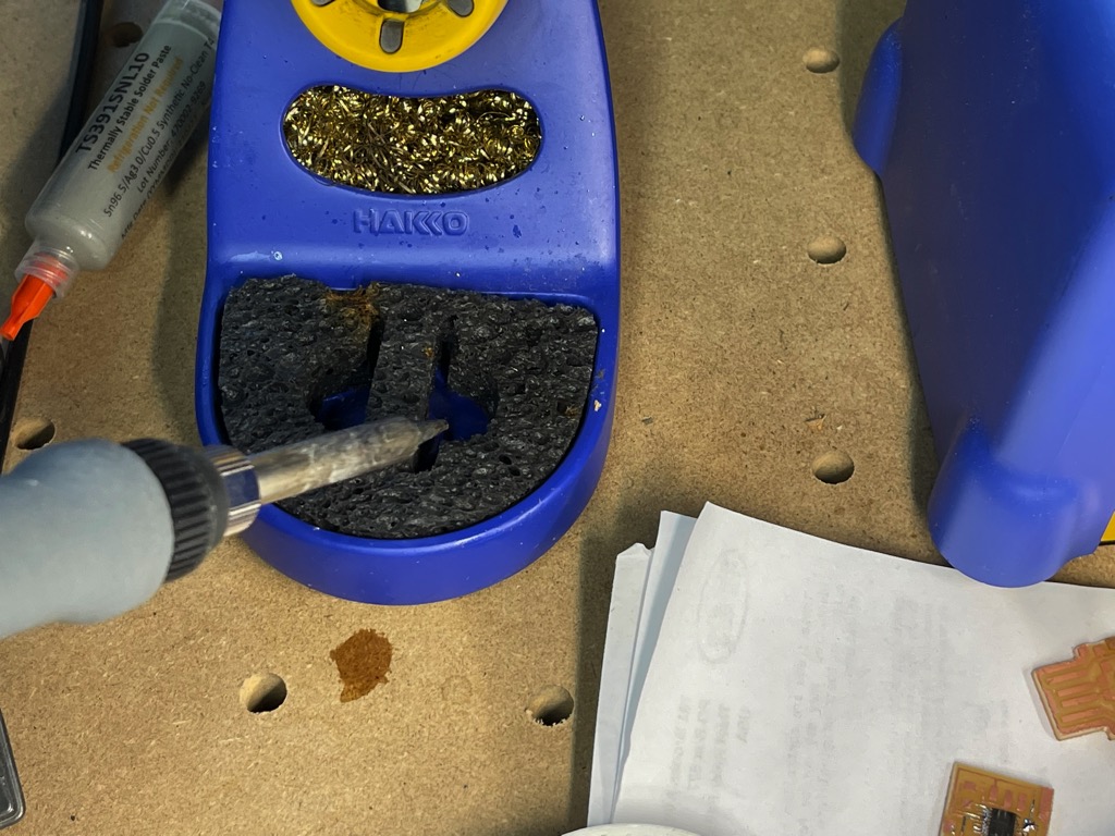
- Some other useful tools for hand soldering:
- Tweezers
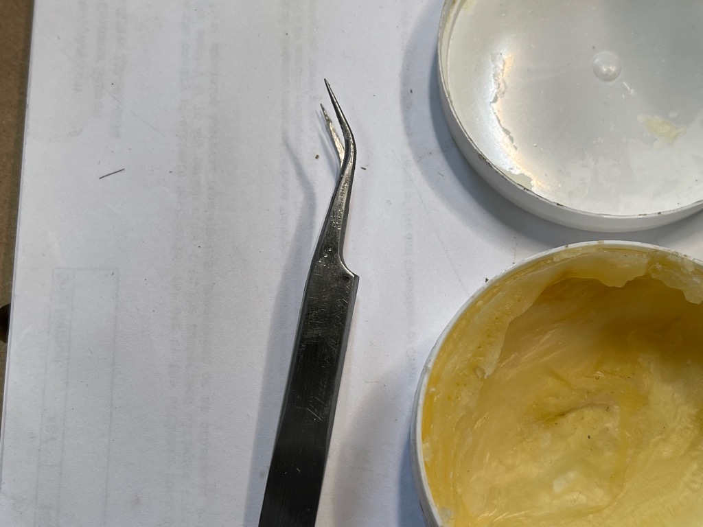
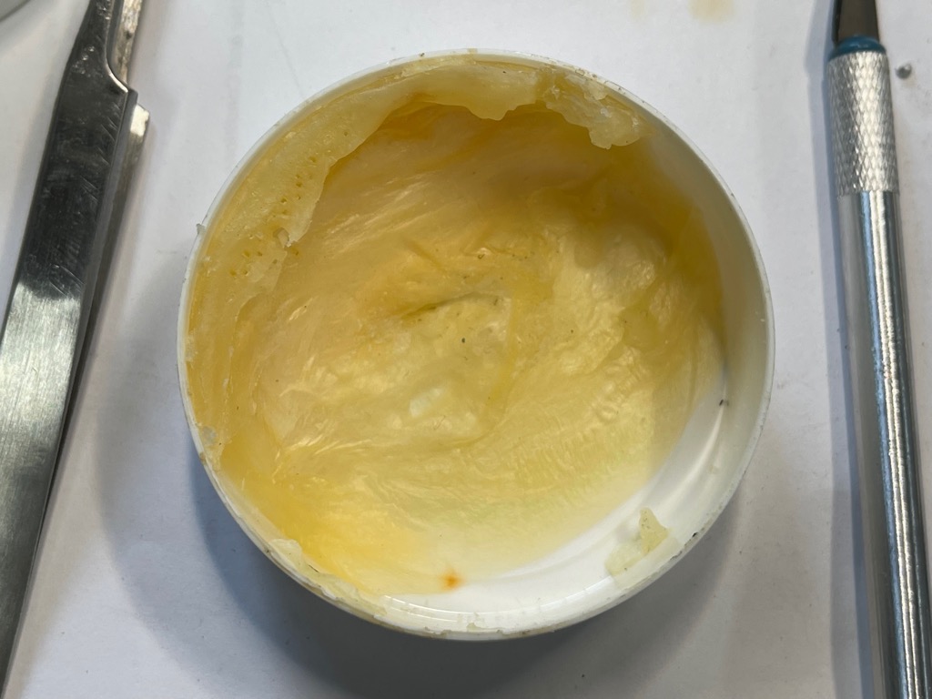
- Solder flux
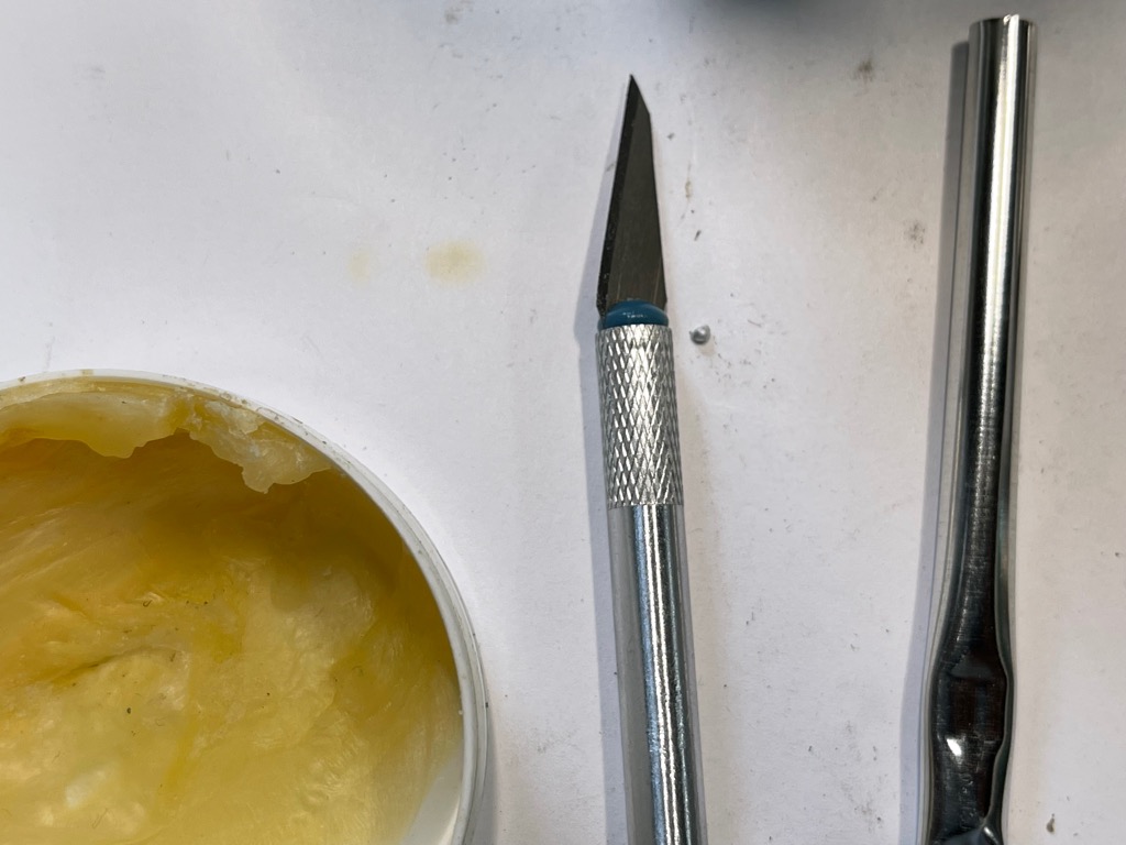
- X-acto-style knife.
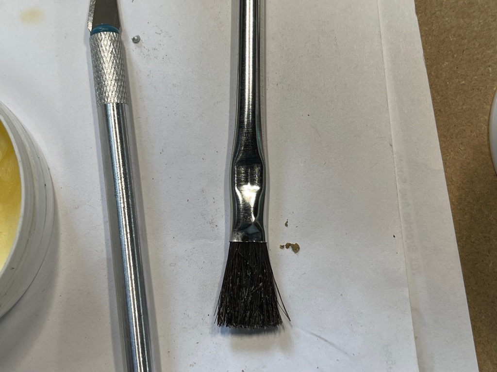
- Flux brush
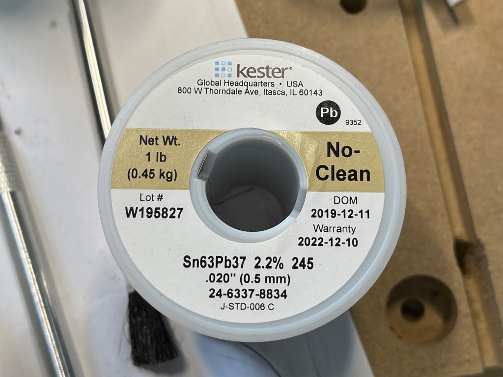
- Solder
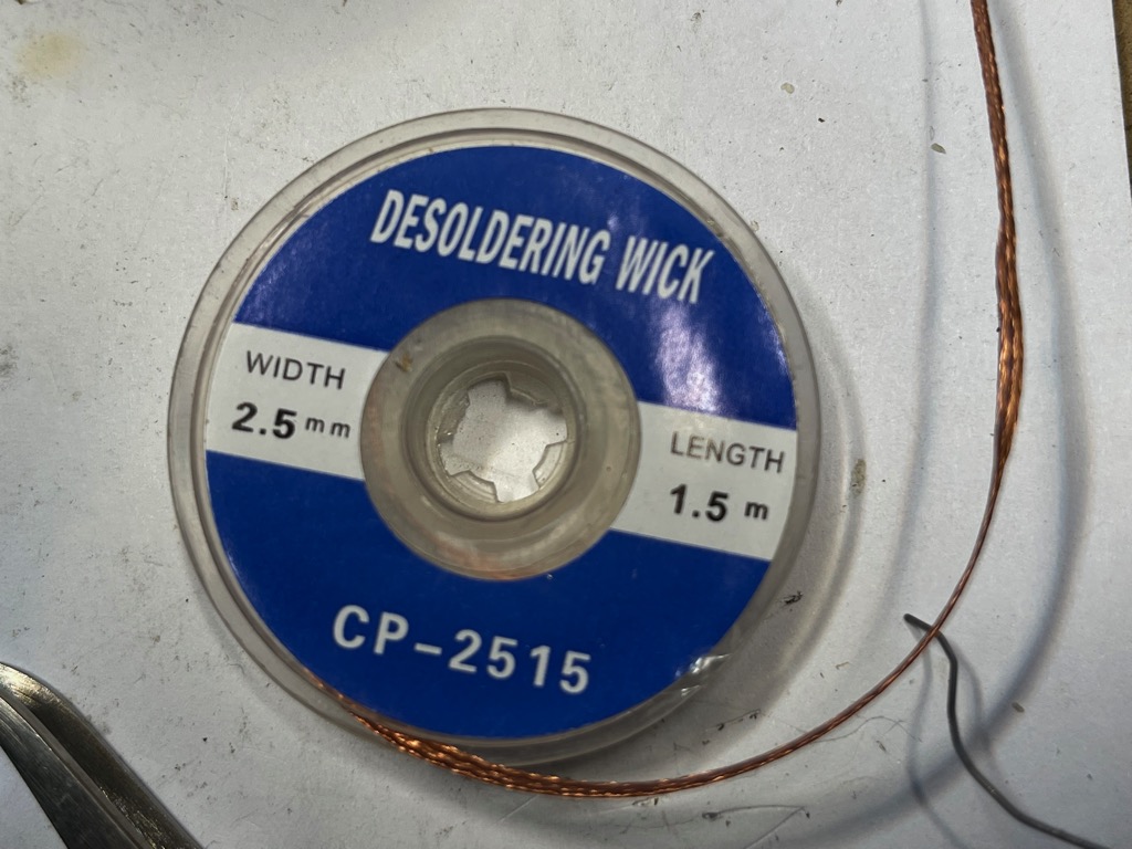
- Desoldering wick
- Solder tip
- Tweezers
-
Note
The iron temperature, solder tip, and wick should correspond to the diminsions of the components on the board.
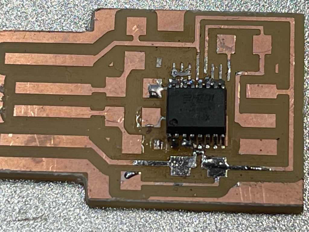
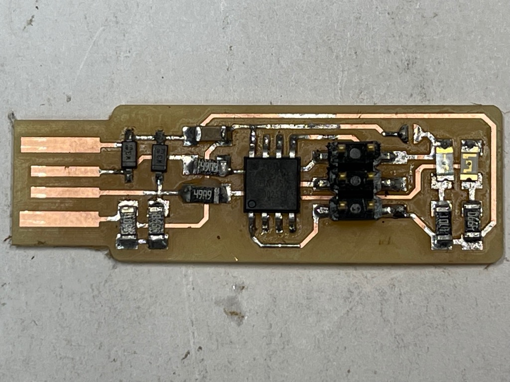
- Solder components to the board
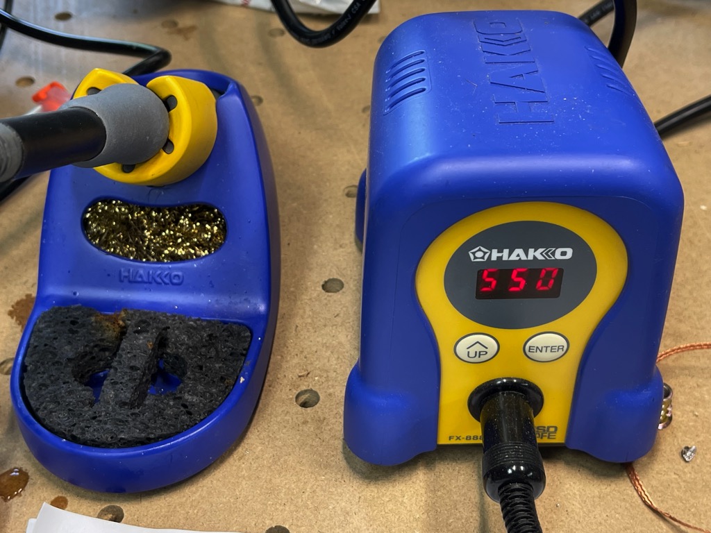
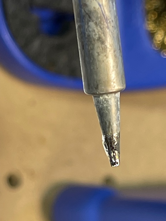
- Turn on the soldering iron.
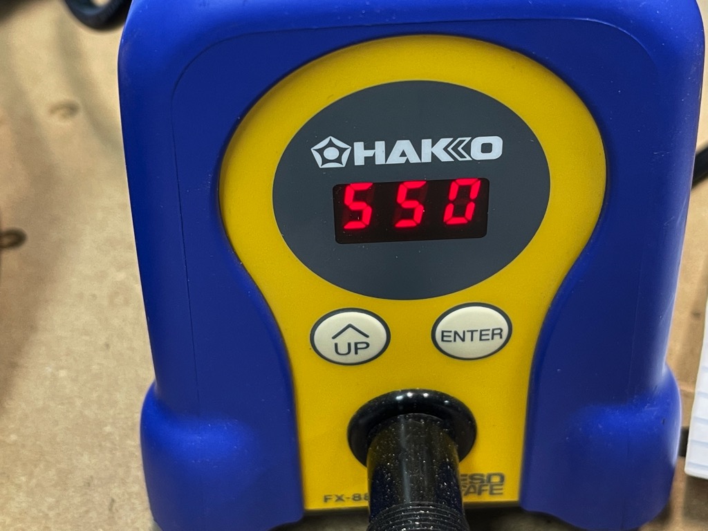
- Set the appropriate temperature. 750degF seemed too hot. I adjusted the temperature to 550degF. Solder wetting was unsatisfactory. I ended with 660degF or 330defC which yielded go results for SMD components.
- Use magnifiers if necessary to better see your work.
- Apply flux to the board with the brush
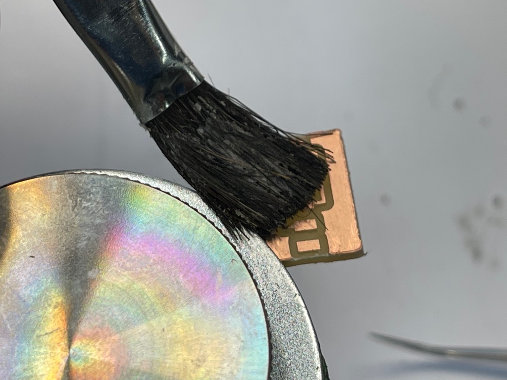
- Solder from the middle out. Start with any microcontrollers in the design.
- Clean the tip
- Tin the tip
- Tin the copper on the board that corresponds to the pins of your first component.
- Ensure that pin one of the component is oriented properly. The package should include a circle or other mark indicating its location.
- Solder it to the appropriate copper pad.
- Solder the pin on the diagonal corner to its copper pad.
- Use the knife to adjust any pins.
- Apply flux to the pins if necessary to promote good wetting.
- Solder the remaining pins.
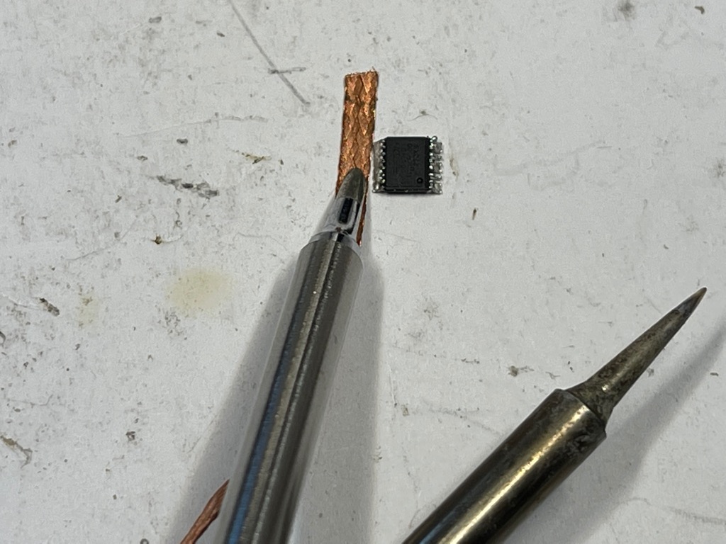
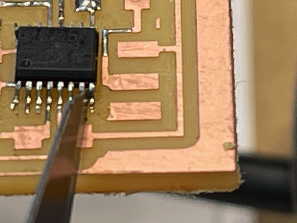
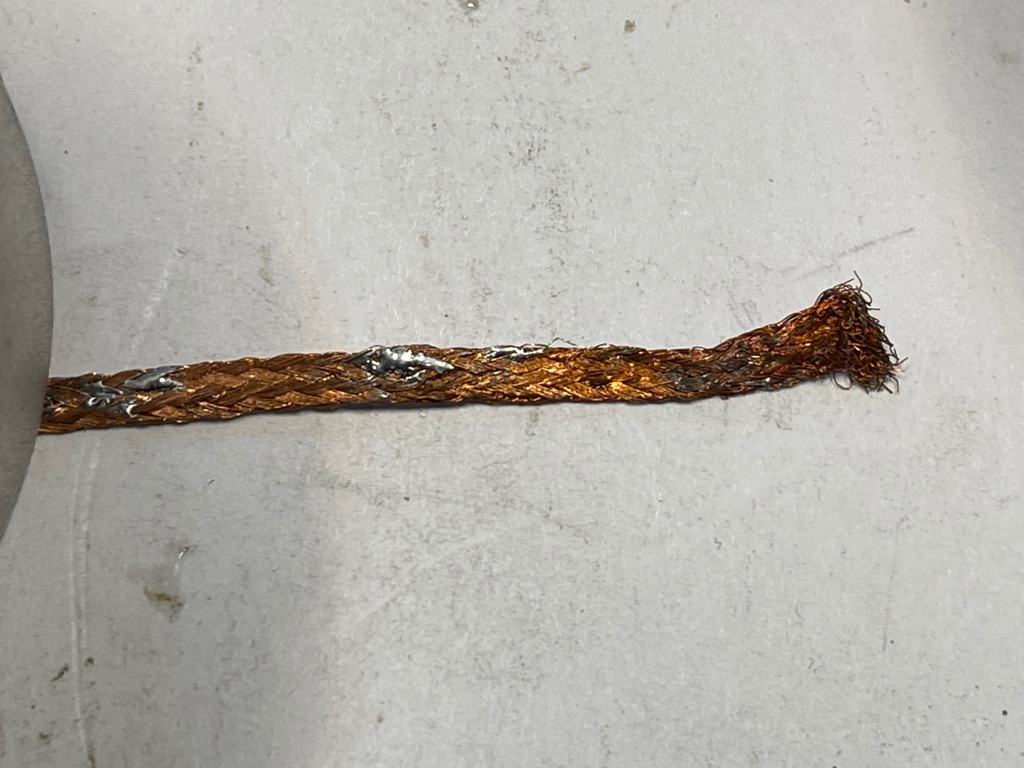
- Remove excess solder using desolder braiding by placing the braid on the area with too much solder then heating the braid with the soldering iron.
- I had to brush flux on my braid for it to draw away the excess solder.
- Braid without flux
- Braid with flux
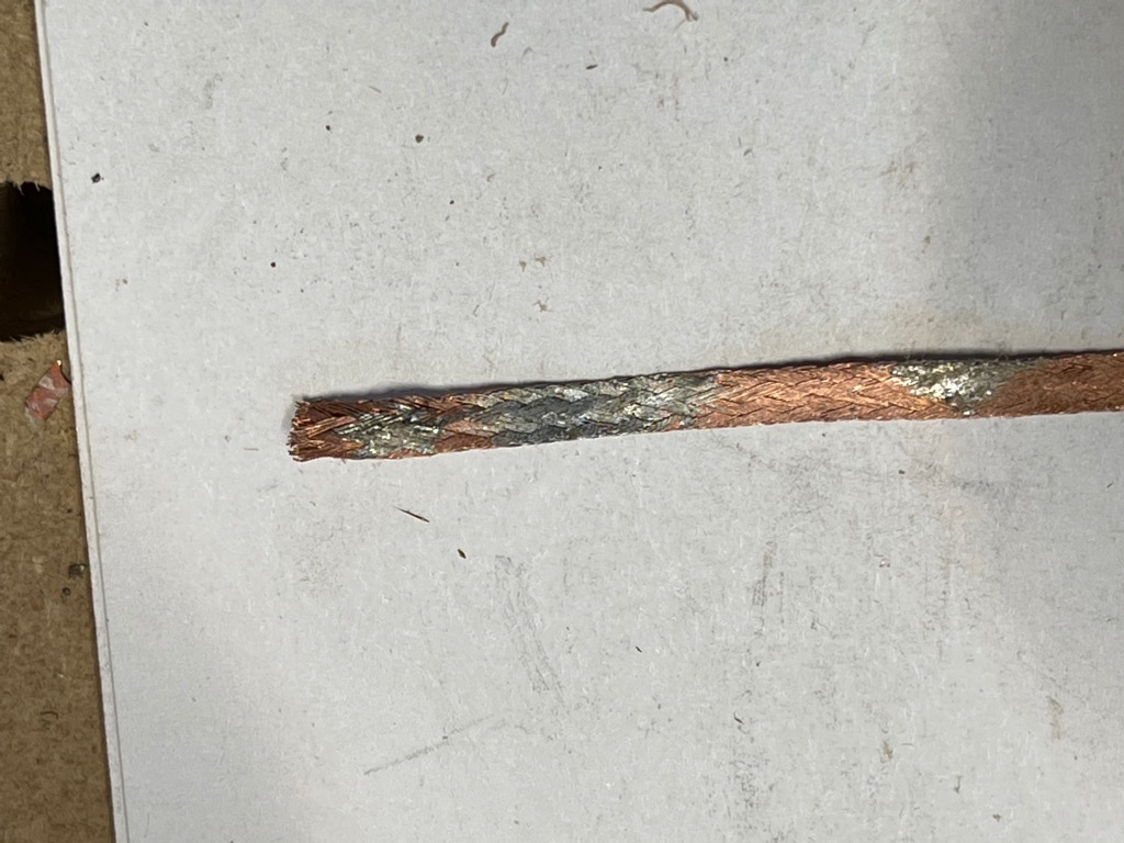
- Braid without flux
- Repeat the above steps to attach the remaining components to the board.
- Turn on the soldering iron.
- Collect components for the FT230 and hello UPDI boards.
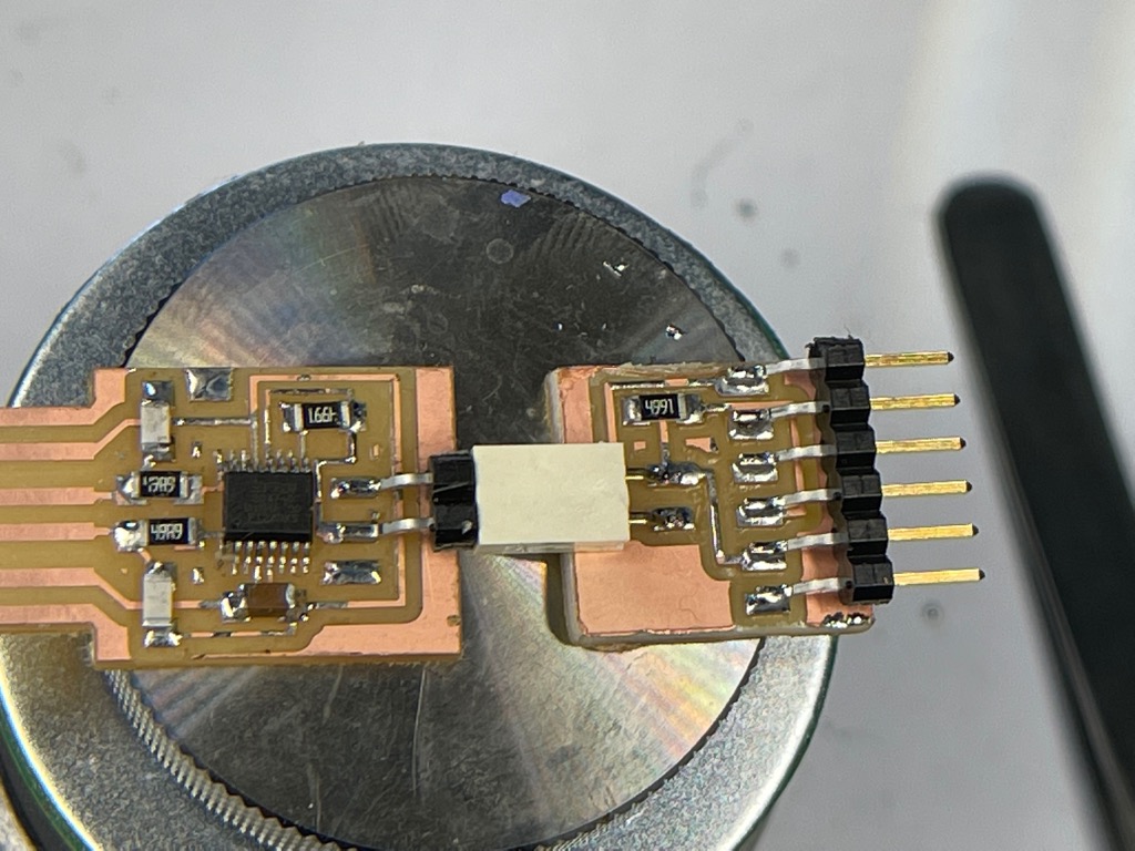
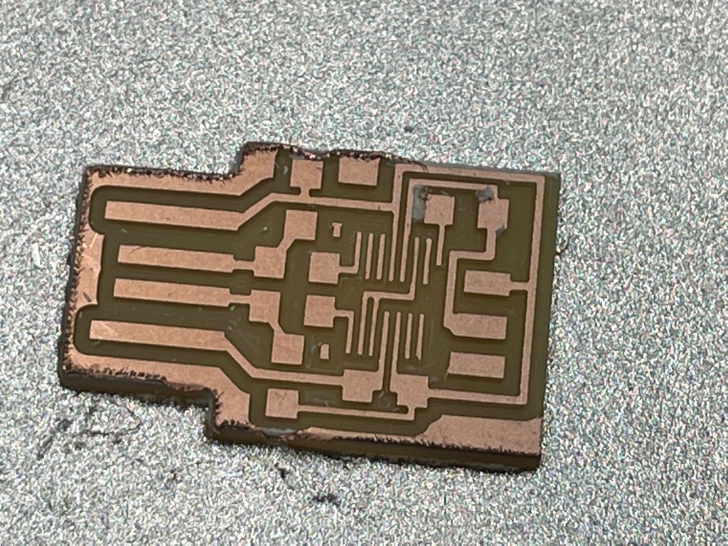
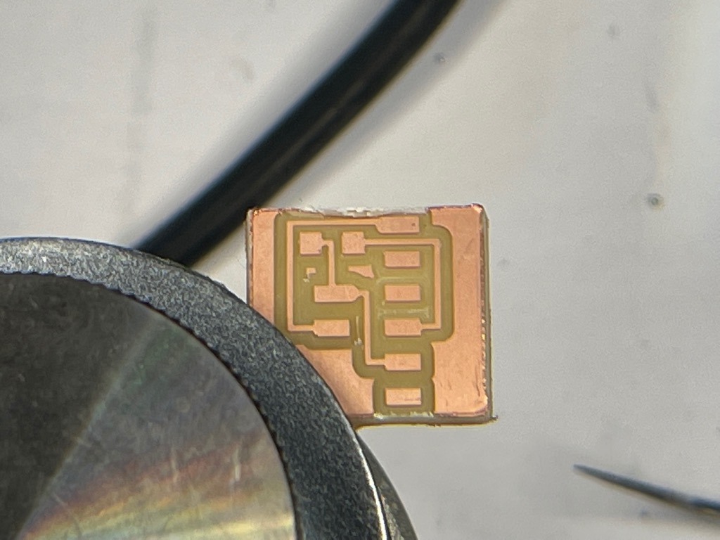
- Produce hello attiny45 ftdi
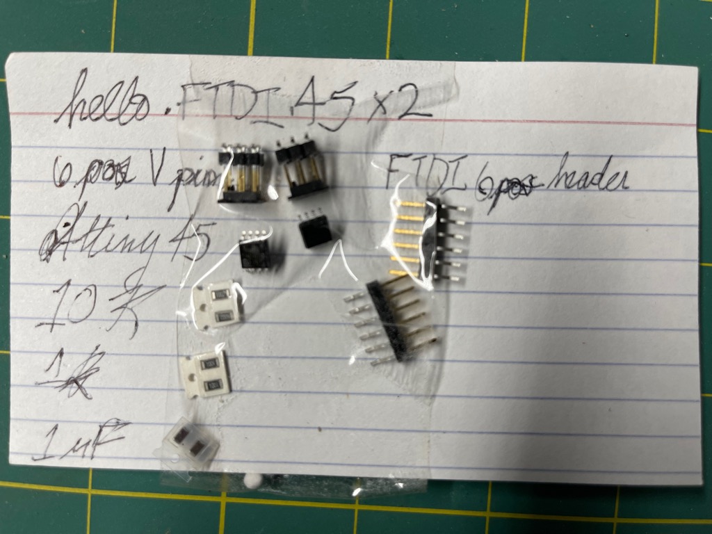

- Produce FabISP
- Test boards
- I used a multimeter to check continuity of passive parts.
- I also checked for some resistance to ensure that there were no shorts between VCC and GND pads of the FT230.
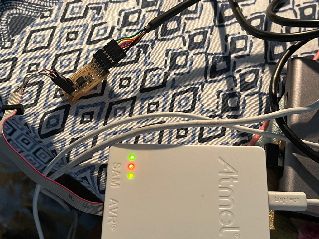
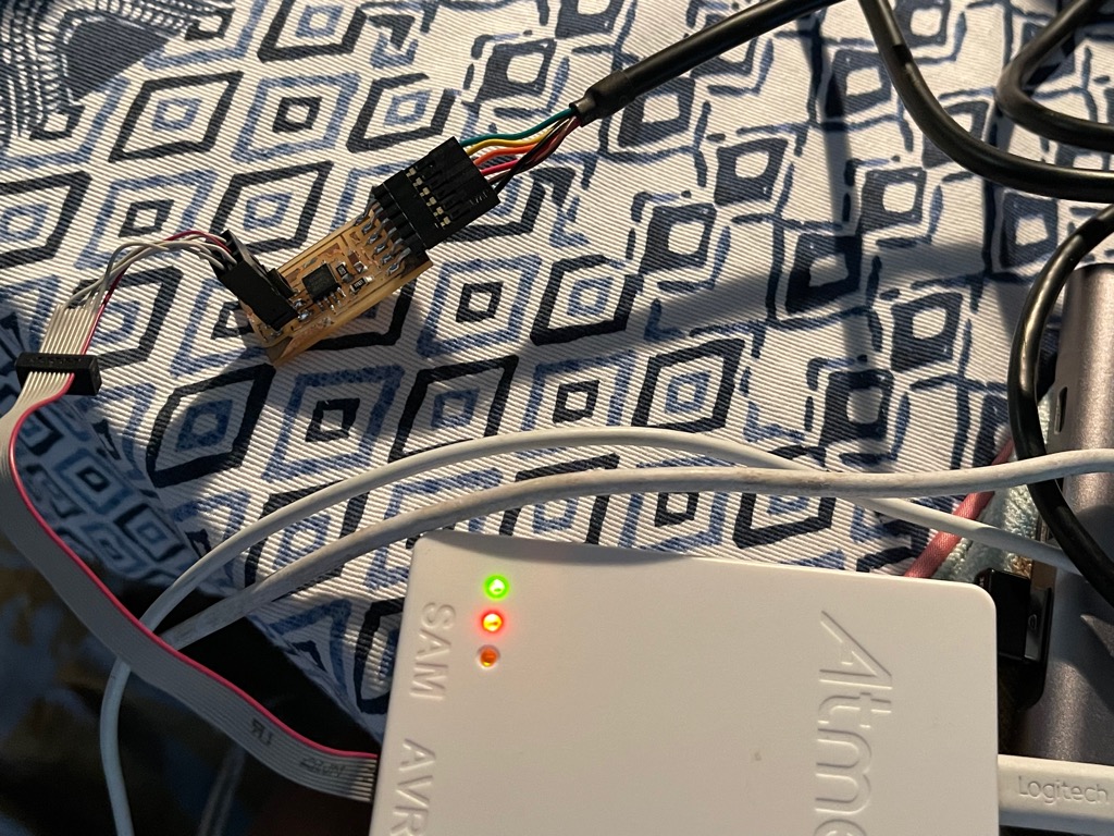
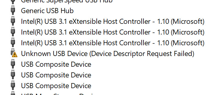
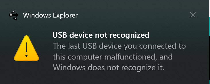
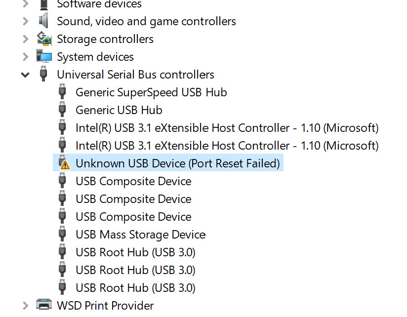
- Setup embedded-programming hardware
- Drivers for programmers
- Connect programmers to computers
- Connect PCBs to computers using programmers
- Setup AVR toolchain on computers
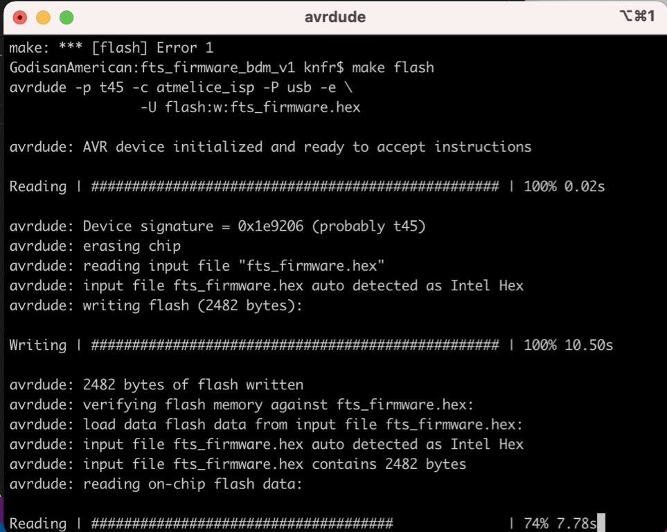
- Program board using AVR tool chain
- Tool chain (MacOS) https://www.obdev.at/products/crosspack/download.html
https://maxembedded.com/2015/06/setting-up-avr-gcc-toolchain-on-linux-and-mac-os-x/
(Mac Bootcamp) https://www.microchip.com/en-us/development-tools-tools-and-software/microchip-studio-for-avr-and-sam-devices#Downloads
ft230xs windows driver https://ftdichip.com/drivers/
https://3os.org/markdownCheatSheet/admonition/
- Controller-machine interface