4. Computer controlled cutting
Due 2024/02/13
How to use this document
Please refer to instructions in the week02 weblog entry
Conceive
-
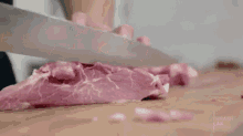
Vinyl cutting is like a knife cutting through steak. A successful cut requires sufficient pressure and a sharp enough tool to split the meat.
-
Laser cutting is like a magnifying glass that concentrates sun light on a piece of paper in order to burn a hole in it except that the laser cutter creates its own light.
Assignments
Learning outcomes
| Have you? | Done |
|---|---|
| Demonstrate and describe parametric 2D modelling processes | Yes |
| Identify and explain processes involved in using the laser cutter | Yes |
| Develop, evaluate and construct a parametric construction kit | Yes |
| Identify and explain processes involved in using the vinyl cutter | Yes |
Checklist questions
| Have you? | Done |
|---|---|
| Linked to the group assignment page? | Yes |
| Explained how you created your parametric design? | Yes |
| Documented how you made your press-fit kit? | Yes |
| Documented how you made something with the vinyl cutter? | Yes |
| Included your original design files? | Yes |
| Included hero shots of your results? | Yes |
Context
- This week we focus on cutting in two dimensions. We cut with vinyl cutter and laser cutter.
- Syllabus FAW04
- Assessment FAW04
- Tutorial FAW04
- Video FAW04
- Review FAW04
- FabAcademy 2021 Documents
- FabAcademy Home Page
- FabLabs Home Page
Vinyl cutting
Comprehend (vinyl)
- Vinyl cutting happens when the machine drags a blade across two-dimensional material. Unlike chip and dust making such as sawing, It creates no kerf and a finished edge ready for immediate use. THEH v1, ch.6-2
- Roland CAMM-1 GS24 vinyl cutter
- Form (We used this pre-COVID)
- Function
- Performance measurments
- Silouette Cameo 4
- Form (Durability rigidity stability–DRS)
- Weight 4.7 kg
- Dimensions 57 cm x 19.5 cm x 17 cm
- Function (Efficiency repeatability accuracy–ERA)
- Work area 30.5 cm x 61 cm with a cutting mat
- Maximum cutting force 2.1 kg for carriage 1, 5 kg for carriage 2
- Form (Durability rigidity stability–DRS)
Take Caution (vinyl)
- Silouette Cameo 4
- Human
- Beware of loose clothing and jewelry.
- Despite the fact that the blades are well shielded, avoid cuts by handling them with care.
- Avoid moving parts when the machine is on.
- Machine
- Do not connect the machine to a non-rated power supply.
- Set up the machine with enough room around it to avoid contact with other objects; avoid areas of excessive noise and vibration; do not store the machine in direct sunlight.
- Do not lubricate the machine; do not use liquids inside the machine.
- Silouette Cameo 4 troubleshooting
- Environment
- Cutting cannot cause fires but poorly maintained power supplies can
- no fluid involved in with cutting
- no fumes involved with cutting
- From Federal Communications Commission: Cameo 4 is a Class B digital device. It may not cause harmful (radio) interference; it must accept any interference received
- Human
Calibrate and characterize (vinyl)
- Silouette Cameo 4 setup & calibration
- Turn on
- Load the tool
- Adjust the white rollers
- Adjust the blades
- characterize
Control (vinyl)
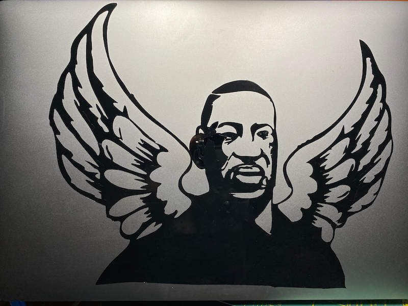
- Human-idea interface
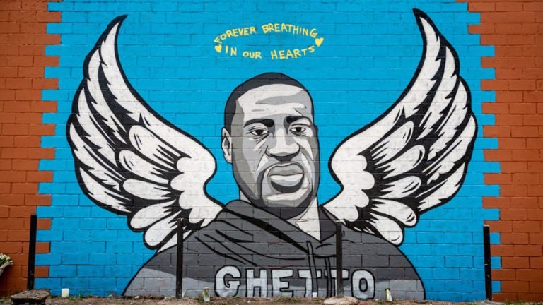
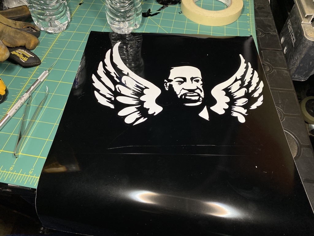
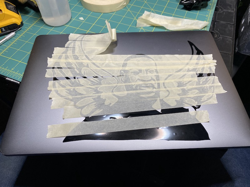
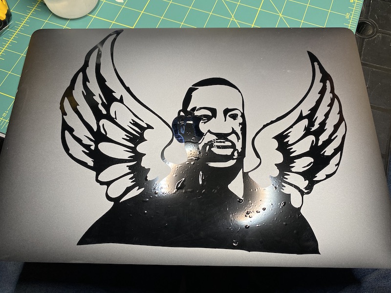
- I made an effort at this assignment before the Covid pandemic. I was dissatisfied with it. After George Floyd’s death, I was inspired to try again.
- Idea-design interface
- Initially, I planned to use Adobe Photoshop to make a black and white image then cut the black portion.

- The resulting image was pixelated. It did not produce clean outlines and was difficult to weed.
- I ended up using Adobe Illustrator instead. Using the Object>Image Trace>Make tool produced much better results.
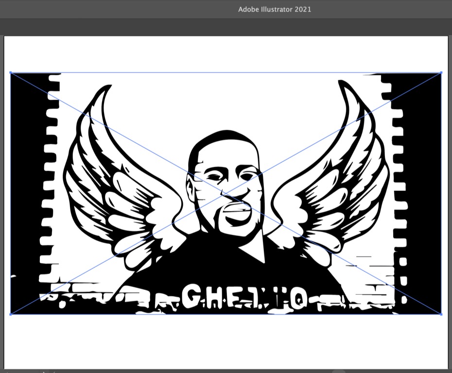
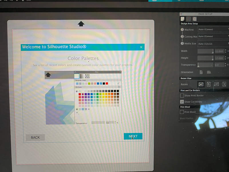
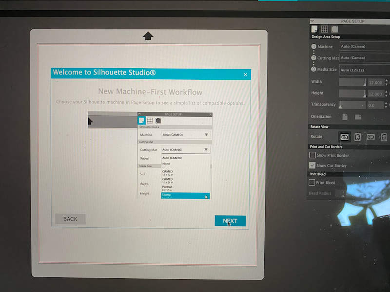
- I then exported a compatible version of the design file to the Silhouette Studio CAM software.
- Initially, I planned to use Adobe Photoshop to make a black and white image then cut the black portion.
- Design-CAM interface (DCI)
- Use Silhouette Studio to define what part of the design should be cut.
- Identify what tools the machine should use
- Identify the toolpaths the machine should take
- CAM-Controller interface (CCI)
- Controller-machine interface (CMI)
-
Machine-material interface (MMI)
-
Silouette Cameo 4
- Materials and sources
- The Cameo will cut paper, cloth, leather and other material
- I only cut vinyl
- I purchased vinyl online from US Cutter
- I purchased vinyl locally from JoAnn Fabrics
- Fixtures
- The Cameo 4 uses three techniques to present material to the machine
- Mat: place the mat on a clean, flat work surface; orient the mat so that “Silhouette is in the upper left corner; position the piece of material on the mat so that its top and left edges sit flush with the top and left sides of the grid on the mat; remove any wrinkles and air bubbles from the material; a tool such as a tile roller can help with this.
- No mat
- Roll
- I used the roll approach
- The Cameo 4 uses three techniques to present material to the machine
- Materials and sources
-
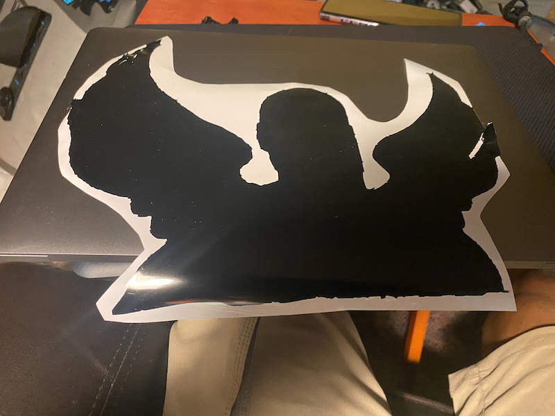
Exacto knife
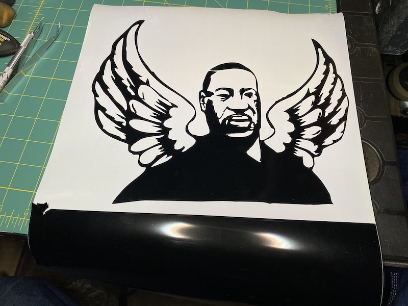
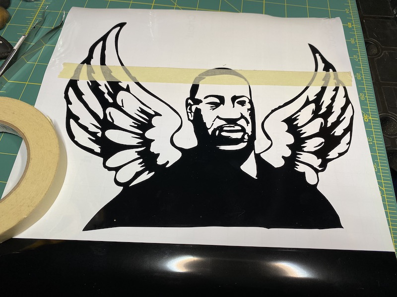
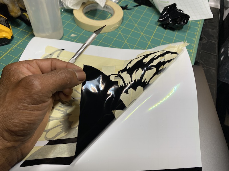
- Once cut, the design must be weeded in order to separate it from the excess material.
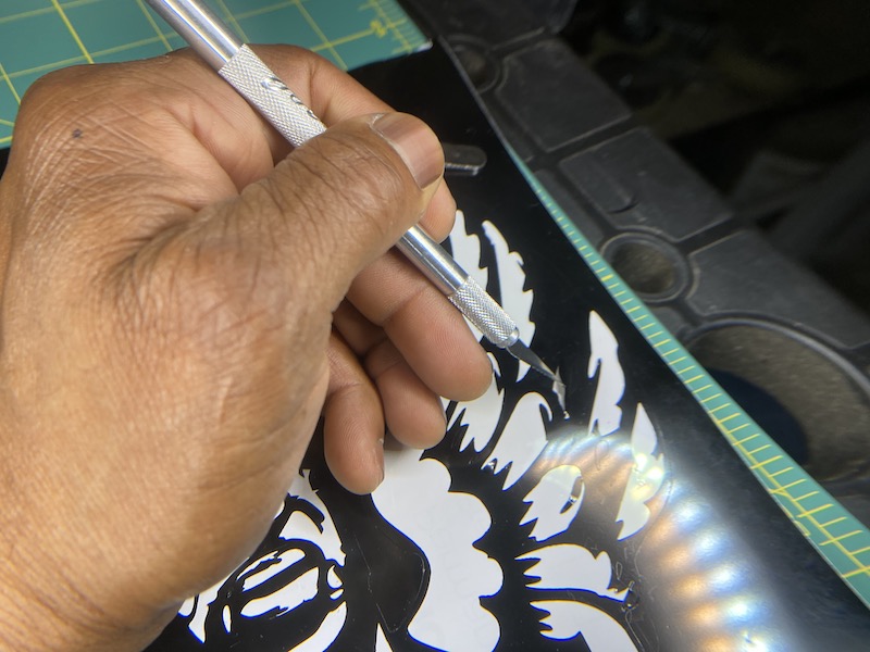
- Once cut, the design must be weeded in order to separate it from the excess material.
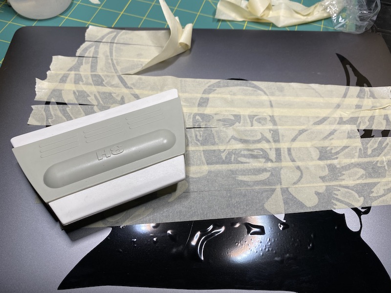
- Transfer tape
- One can transfer a weeded image to the display surface using transfer tape.
- One can transfer a weeded image to the display surface using transfer tape.
-
Laser cutting
Comprehend (laser)
- Laser cutting happens when a focused beam of light caused by electrical energy exciting electrons in a gas burns a path in material. While t does create some kerf, it also produces a finished edge. TMEH v.1,ch.14-62
- Epilog Legend 36 EXT
- Glowforge Pro laser cutter
- Form
- Weight:
- Dimensions: 965 mm x 527 mm x 210 mm
- Case: high modulus, infection-molded plastic
- Linear System: Custom extruded aluminum linear rails with belt driven v-wheel carrier
- Motion: Dual hybrid stepper Y axis; single hybrid stepper X axis
- Cooling: Closed loop self contained internal cooling.
- Air Assist: Internal air assist with no external compressor hookup required
- Recommended Operating Temperature: 60F-81F (16C-27C) Pro
- Laser: CO2 45 W operating at 10,600 nm wavelength
- Fixed Alignment: Factory calibrated optical system does not require any alignment by the user
- Sealed Optics: Enclosed optical path with cleanable and replaceable windows protects the laser optics to avoid replacement or realignment
- Peak power consumption: 800 W
- Function
- Work volume (maximum) 279 mm x 495 mm x 13 mm
- Performance measurements
- Form
Take Caution (laser)
- Glowforge Pro
Calibrate and characterize (Laser)
- Glowforge Pro setup
- Glowforge Pro calibrate camera
- Glowforge characterization
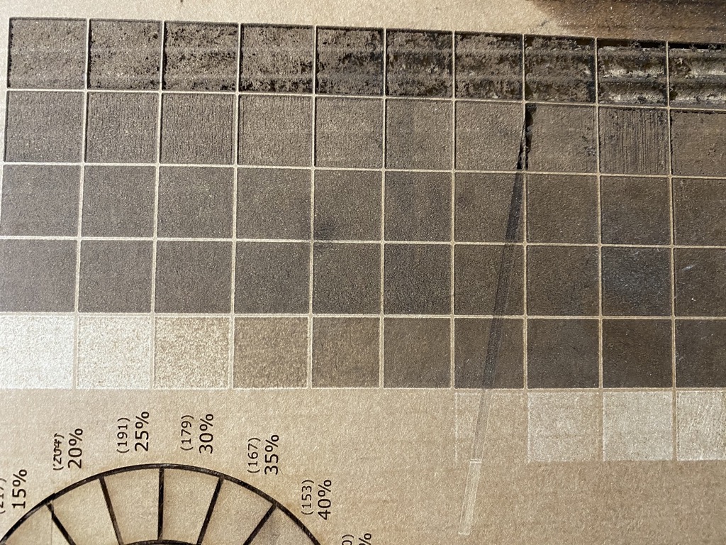
- Test patterns for shades
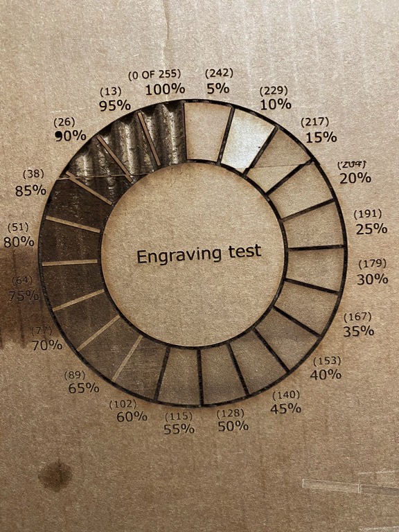
- Engrave test pattern
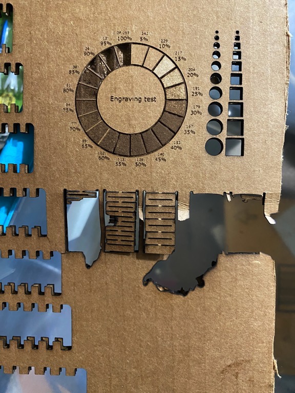
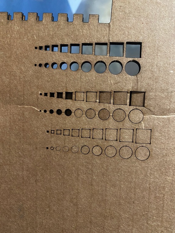
- Gap gauges
Control (laser)
- I want to make a geodesic kit. I want to connect the piece with something more than a friction piece cut to a specific angle.
- Find boackground
- search “draw geodesic dome in fusion 360.”
- Search “geodesic dome theory.”
- This Instructable and this
- EPCM white paper
- Search “icosahedron geodesic dome math.:
- Search “uniform polyhedron icosahedron.”
- Search “platonic solid.”
- Platonic solid from Wikipedia Check out icosahedron animation.
- Plato from Wikipedia espoused
- Rabbit hole!
- I wondered why Plato used geometric solids to represent the classic elements fire, water, air, earth, and wind.
- I was reminded that Plato, his teacher Socrates, and his student Aristotle were all influenced by Pythagoras.
- Representing nature with solids seems (ha) natural to me. Visualization expedites knowledge creation and concept comprehension.
- Western philosophers combined learned geometry in Africa.
- I speculate that they learned to combine geometry and logic in Africa as well.
- These two elements are necessary if not sufficient for scientific method and knowledge creation.
- Arithmetic and maths can refine understanding but can impede initial comprehension of concepts.
- I believe that geometry should be part of the trivium instead of the quadrivium. That is children should learn logic and geometry before arithmetic.
- St. Augustine also lived and studied in Africa.
- He made significant contributions to modern, Western Christianity because of his logical approach to the spiritual system.
- I believe that the ancients understood that the “African ethos” provides humans with the most efficient path to creativity.
- Wolfram Mathworld
- Design press-fit kit using Fusion 360
- Prepare Fusion 360 to create a design.
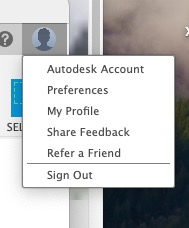
- Launch Fusion 360 and login to Autodesk account if necessary.
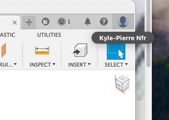
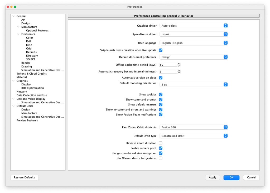
- Set Preferences under the user icon as needed.
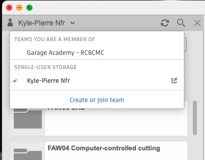
- Fusion orders folders and files according to Teams. Confirm that the correct Team is selected.
- Start design
- Initialize a new design with one of the following methods:
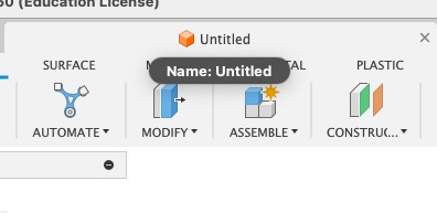
- Fusion 360 launches with an untitled Design by default.
- Click on the plus sign tab to initialize a Design.
- Select File>New Design
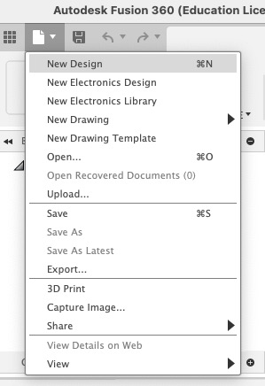
- Fusion 360 launches with an untitled Design by default.
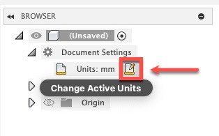
- Set the correct dimensions for the Design.
- Begin design
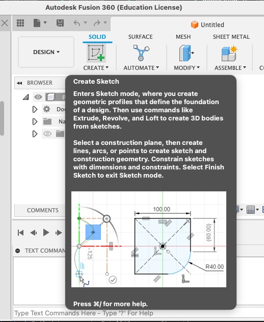
- Create>Create Sketch
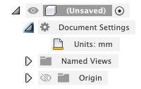
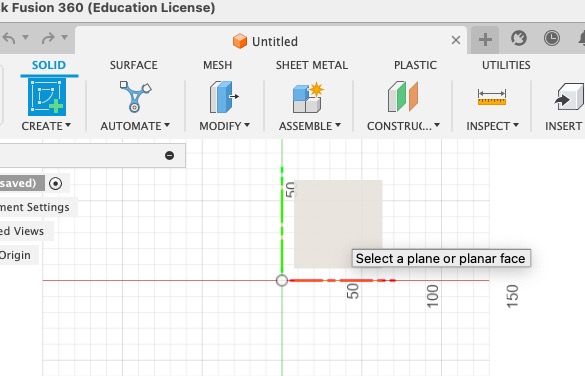
- Select plane upon which to sketch.
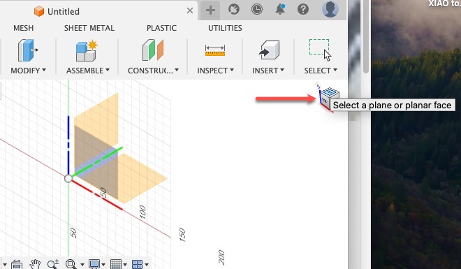
- We choose Top
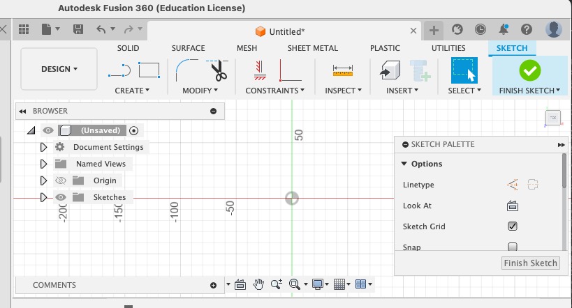
- On the Project tree, under Origin, this corresponds to the XY plane
- Create>Create Sketch
- Initialize a new design with one of the following methods:
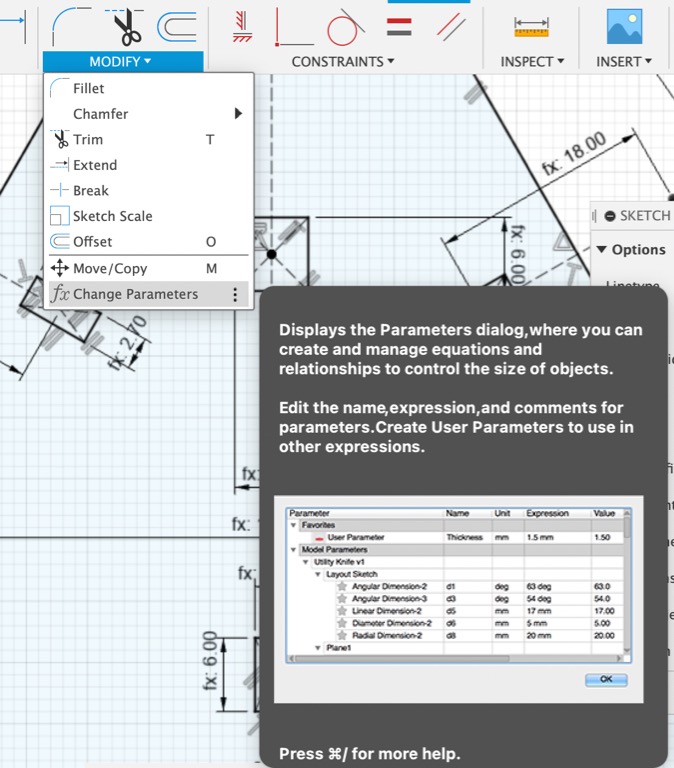
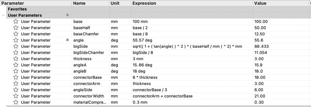
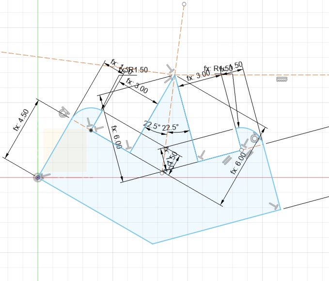
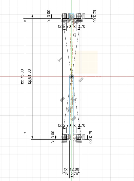
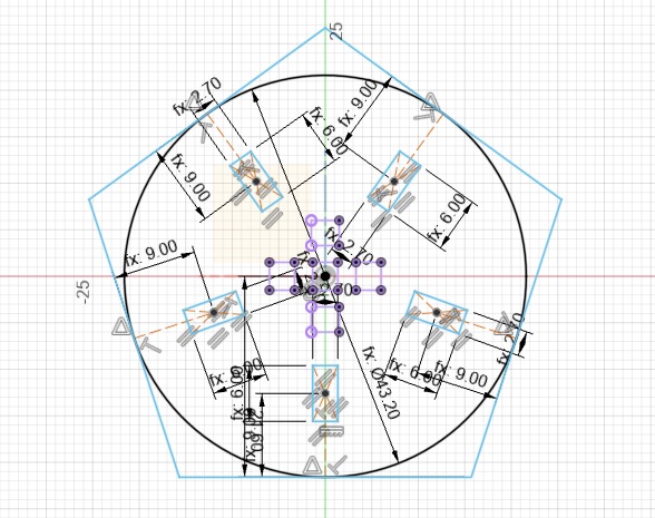
- Before sketching anything, I used Modify>Change Parameters to define some User Parameters in order to easily reuse common dimensions.
- Prepare Fusion 360 to create a design.
- Complete design
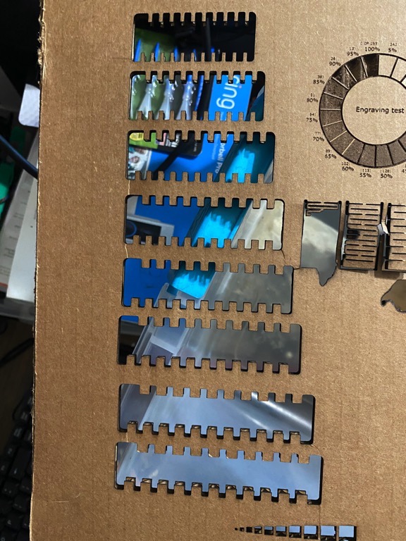
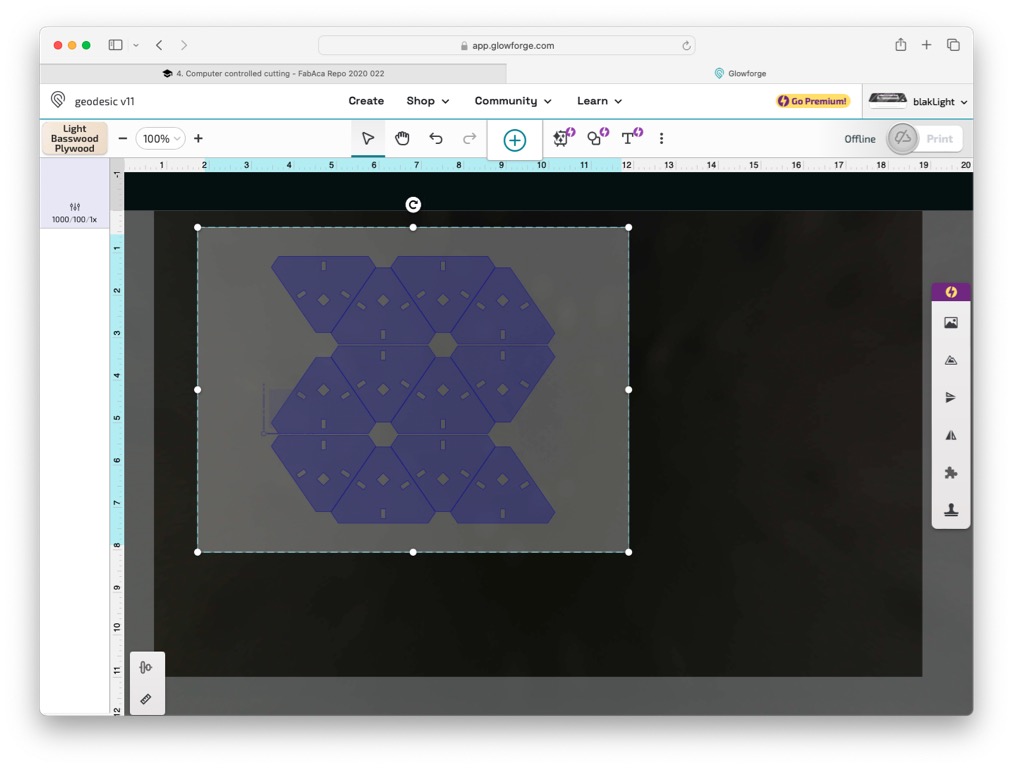
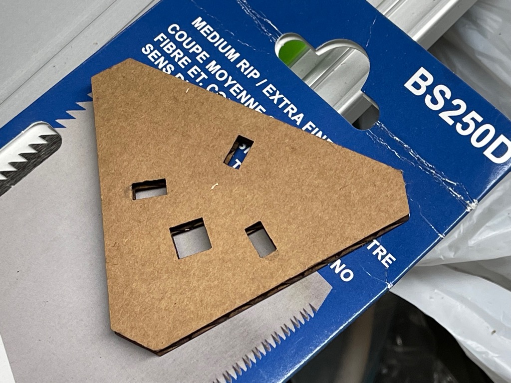
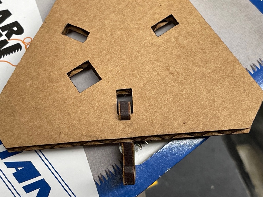
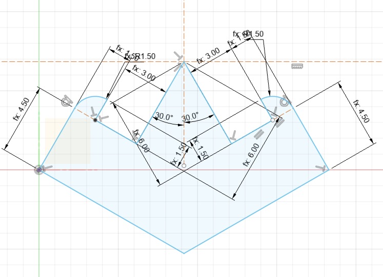
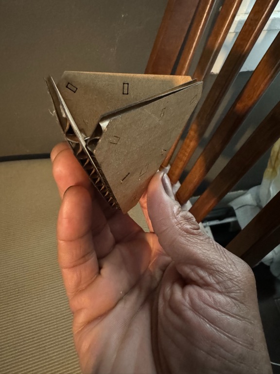
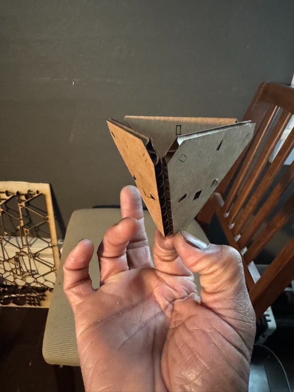
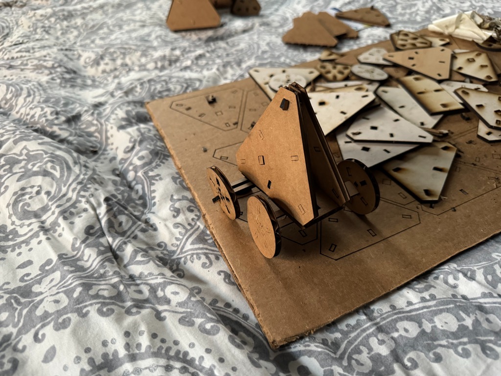
- The 2V Icosahedral 2/3 geodesic dome uses two triangles.
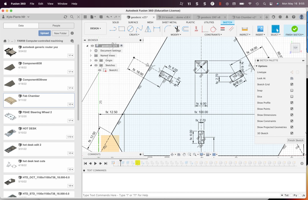
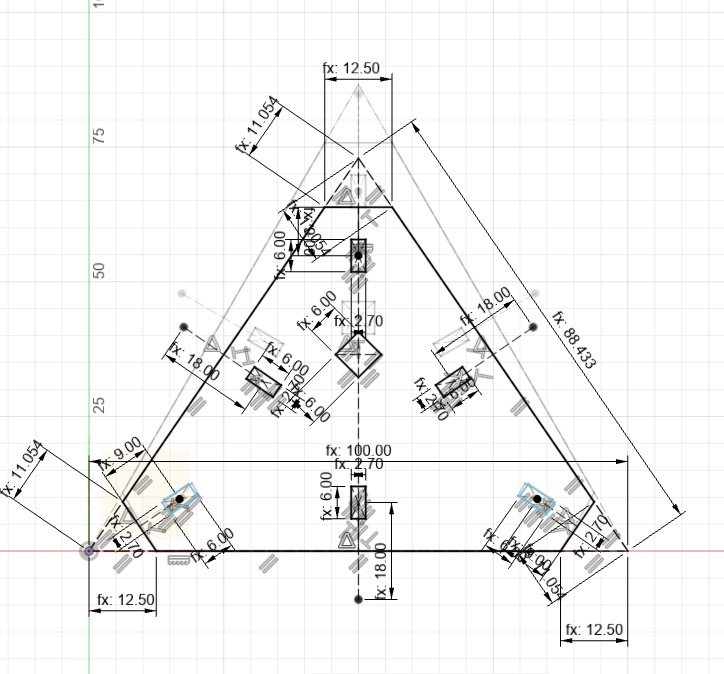
- I tried to make triangles with Create>inscribed>polygon of three sides but that did not work. I used line segments instead to make the basic triangles.
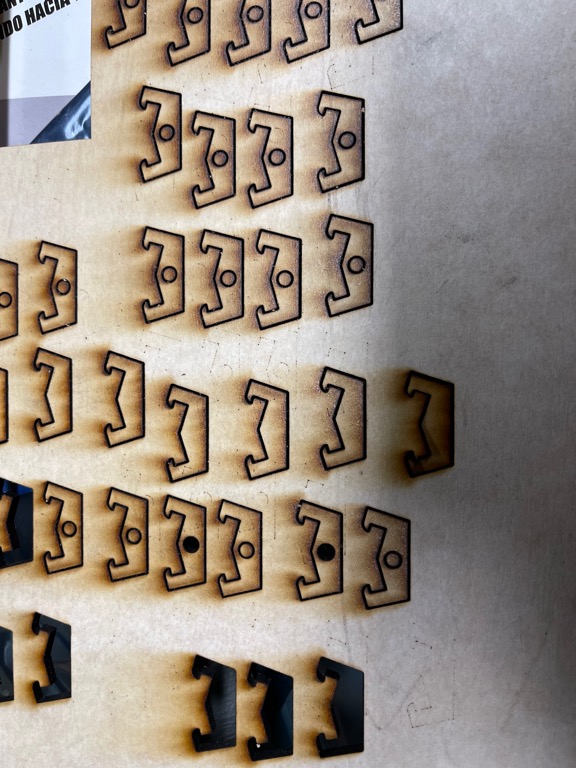
- I designed these connectors to account for the appropriate angles for the dome and sphere construction.
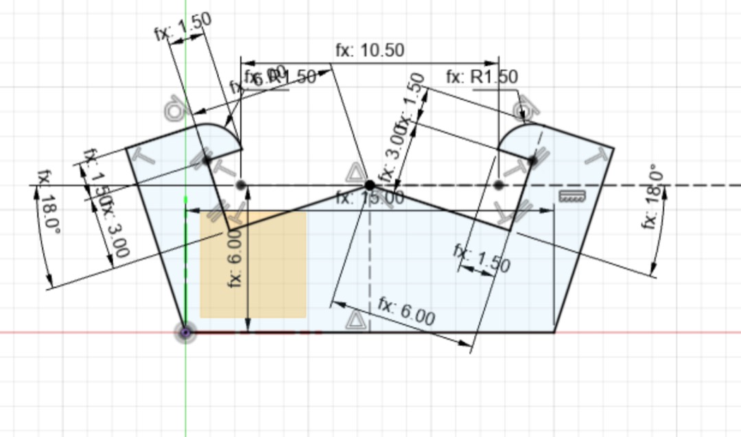
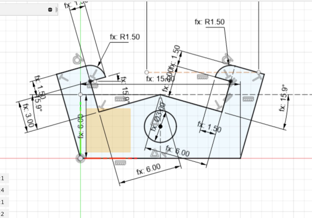
- The 2V Icosahedral 2/3 geodesic dome uses two triangles.
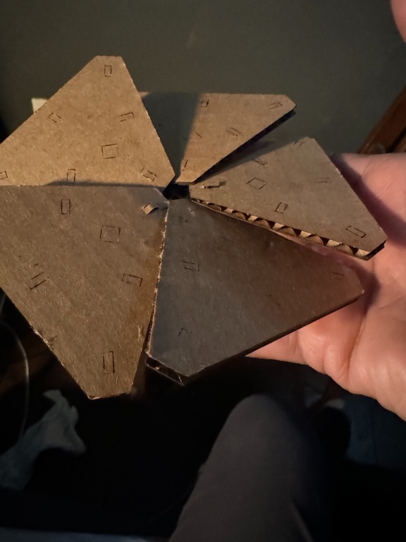
- Laser cut pieces
- Export design as .svg from Fusion 360.
- The Glowforge app takes dxf and svg file formats.
- For DXF, right-click on sketch of part that you want to export. then >Save as DXF.
- For SVG, use Shaper Utilities Add-On
- After installing the Add-On, go to the Utilities tab and select Export-to-Origin icon.
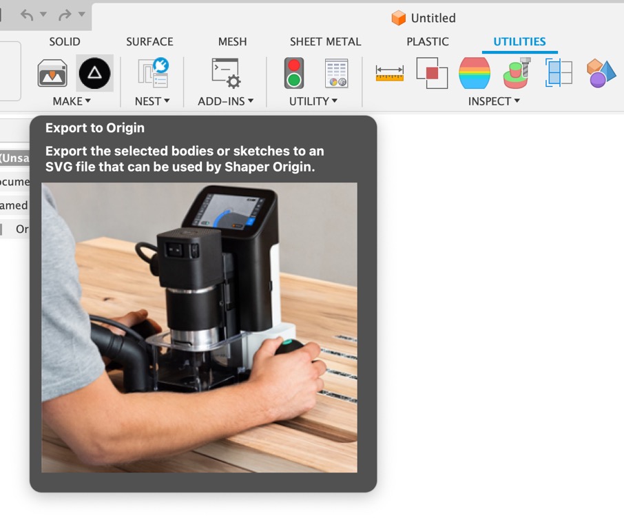
- To Select different input types, tick the Advanced box in the popup.
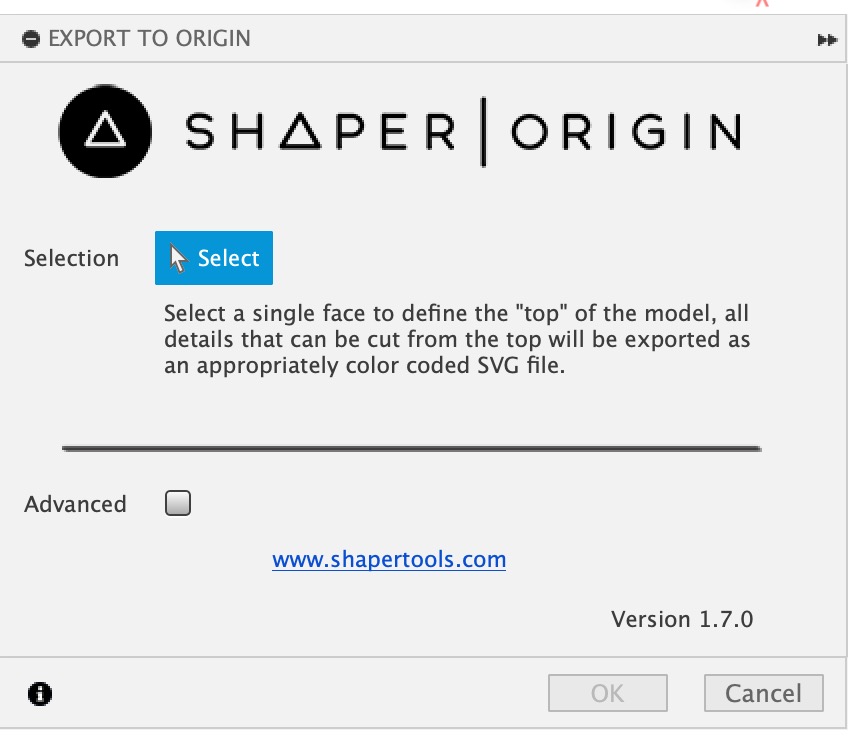
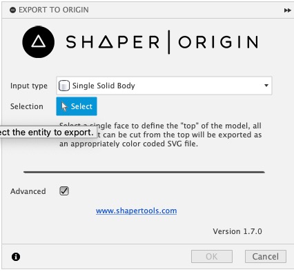
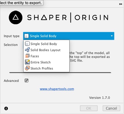
- Select the body or elements that you want to export as SVG
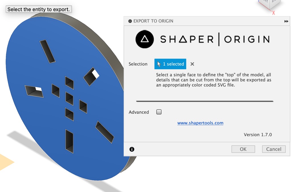
- Click OK.
- Name and Save the SVG file.
- After installing the Add-On, go to the Utilities tab and select Export-to-Origin icon.
- Use Glowforge laser cutter.
- Begin a new layout in Glowforge.
- Import SVG or DXF files
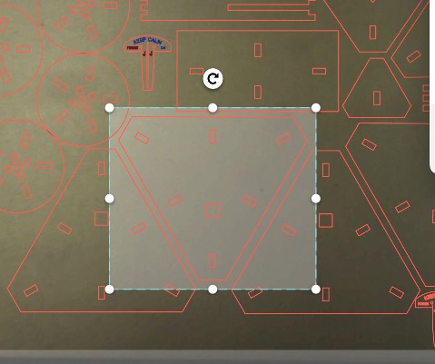
- Place the parts on the cutting area.
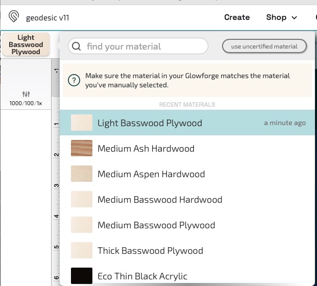
- Select material of the work-piece.
- Choose part to edit and Select cut type.
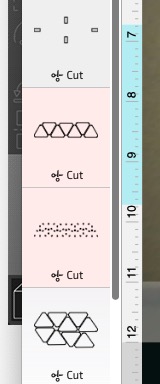
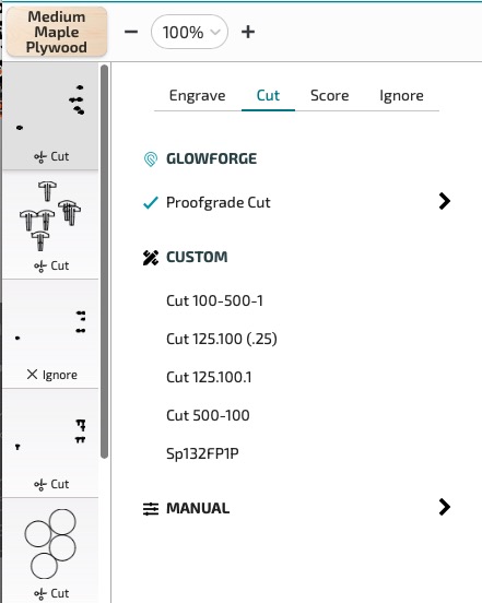
- Choose part to edit and Select cut type.
- Press print button in app to Send file to laser cutter.
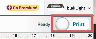
- Press Print button on laser cutter to cut the parts.
- Begin a new layout in Glowforge.
- Export design as .svg from Fusion 360.
- Increase functionality of kit
- Add additional connection holes.

- Make additional connectors.
- Make different geometries
- Add additional connection holes.
- Some examples
- open flower/pin wheel

- snake
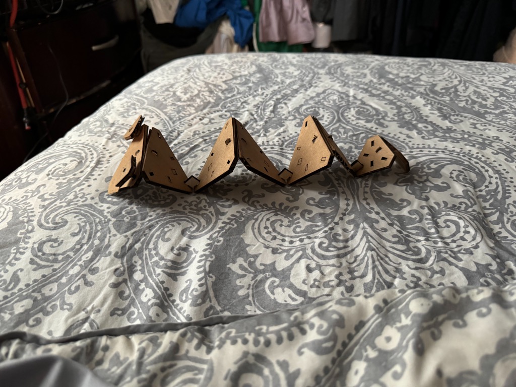
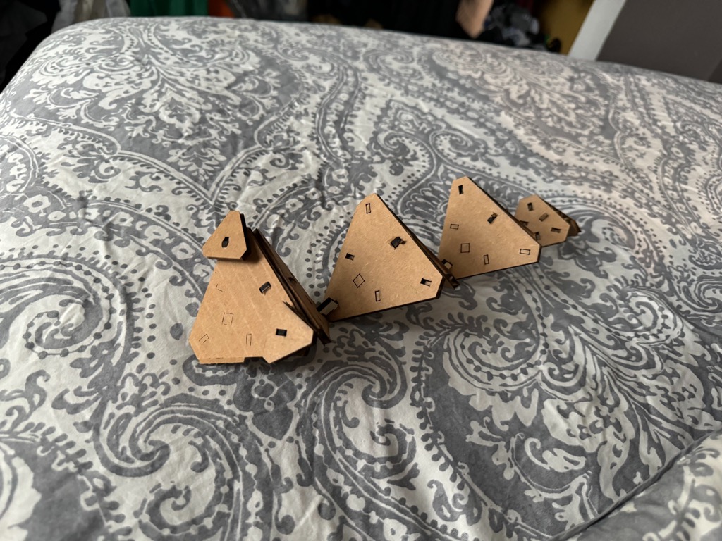
- tulip or cup
- car
Return to assignments
- open flower/pin wheel