11. Input devices
Assignment:
-
[x] individual assignment: measure something: add a sensor to a microcontroller board that you have designed and read it
-
[ ] group assignment: probe an input device’s analog levels and digital signals
Summary
This week, I completed the design and fabrication of my mainboard, including a ATmega328P with a 2OMHz resonator and fanout of all the pins to pinheaders, on which I could connect external PCB’s (shields) for input or output devices, supply boards, etc… This week, I connect it to a DHT222 click from Mikroelektronika, to get the ambient temperature and humidity.
I’ve used double sided PCB, eased the solder process by using a magnifying instrument, struggled with the 1-wire protocol and the Arduino environment.
Future development will be to use the I2C protocol and get rid of the Arduino dependencies, going back to the AVR sources.
Files are available here
Individual assignment
Thinking in my final project, I would like to use temperature and humidity sensors, as well as light and presence ( movement) detectors, and a bluetooth module to communicate with some external application.
Main board
STEP 1: PCB Design
In order to have a quite versatile system, I was thinking to develop a main board with the main microontroller, into which we can plug different input/output devices. So I will have to develop the main board and others small boards to accommodate my input/output devices.
So, I reuse the ATmega328 board I started to design in week07, but having to adapt the netlist manually (all resistors, diodes and capacitors remain unconnected whatever action I take in the schematics!!), routing is a too heavy job, and I decided to modify/simplify the board as follows:
remove the battery management and keep power pins as +5V pins on the board
use a double-sided PCB in order to send some routing on the back
* add through hole connectors to make the connections between top and bottom layer without using small vias
* add additional 5V and GND pins on pinheader to ease external connections to input and output devices
Here is the schematic:

And the gerber files (after quite a lot of hours of patience, doing, redoing and undoing things), reflecting the layout:


And the drill map:

The complete files are available here.
STEP 2: PCB Fabrication
I mill the PCB on a double-sided FR1 board (standard size 127 x 101.6 x 1.70mm) on the Bantam milling machine, following the same process as in week07.
Therefore, I load the three gerber files of the outline, top and bottom layers, as created by Kicad, as well as the drill file, into the Bantam software.

Due to a break of the 1/64” flat end mill during the material thickness test, and having no spare part, I have to mill the top PCB with the metal engraving bit 0.005”....
I start to mill the top layer… About 30 minutes job....

Next step is to make the holes: I use a 1/32” flat end mill therefore. Another 10 minutes job.

When the top layer is milled, I just flip the PCB on the Bantam plate, the software handles the mirroring of the gerber file automatically, provided the PCB is correctly aligned… Milling with the metal engraving bit 0.005” is a 15 minutes job.
The mistake I made for a first test is to leave the alignment at the left bracket origin alignment, which caused a misalignment of the drill holes in the top and bottom layer pads!! When flipping the PCB, it now has to be aligned at the other side bracket(here, right side then)!

And last step is to cut the outline, with the 1/32”flat end mill, 15 minutes job.

Failed ! In addition to the shift of the drill holes in a first test, some traces, being to thin, have been milled!
| top layer | bottom layer |
|---|---|
 |
 |
Redesigning with a 0.5mm width for the tracks and taking into account the realignment of the PCB solve the issues:
| top layer | bottom layer |
|---|---|
 |
 |
STEP3: PCB assembly and testing
The Bill of materials is as follows:
| Id | Designator | Description | Quantity |
|---|---|---|---|
| 1 | JP5 | PinHeader_1x12_P2.54mm_Vertical | 1 |
| 2 | JP3 | PinHeader_1x12_P2.54mm_Vertical | 1 |
| 3 | JP4 | PinHeader_1x12_P2.54mm_Vertical | 1 |
| 4 | R2,R3 | 330 R R_1206_3216Metric_Pad1.42x1.75mm_HandSolder | 2 |
| 5 | JP2 | SPI connetor: PinHeader_2x03_P2.54mm_Vertical | 1 |
| 6 | Y1 | 20MHz Resonator_SMD_Kyocera-3Pin_7.4x3.4mm_HandSoldering | 1 |
| 7 | U1 | ATmega328P-AU TQFP-32_7x7mm_P0.8mm | 1 |
| 8 | S1 | Push buttonFSM-SWITCH | 1 |
| 9 | R1 | 10K R_1206_3216Metric_Pad1.42x1.75mm_HandSolder | 1 |
| 10 | JP1 | FTDI PinHeader_1x6_P2.54mm_Vertical-GVV | 1 |
| 11 | D2 | RED LED_1206_3216Metric_Pad1.42x1.75mm_HandSolder | 1 |
| 12 | D1 | GREEN LED_1206_3216Metric_Pad1.42x1.75mm_HandSolder | 1 |
| 13 | C5,C2,C1 | 0.1uF C_1206_3216Metric_Pad1.42x1.75mm_HandSolder | 3 |
| 14 | C4 | 1.0uF C_1206_3216Metric_Pad1.42x1.75mm_HandSolder | 1 |
| 15 | C3 | 47uF C_2816_7142Metric_Pad3.20x4.45mm_HandSolder | 1 |
Assembly of the ATmega328 is here the challenge, the other components are easy to solder....
The soldering process is done below a magnifier glass. No major problem, except that ensuring the contact between top and bottom pads through the pins of the pin headers requires a bit of dexterity and patience, as the holes are non plated; extra solder is required on the bottom pad while pushing and moving a bit the pin with the solder iron tip to help the solder flow to the opposite side (top side).

|

|
Hardware testing is done as previously in week05 and week07 (continuity check on multimeter), nothing new. Extra care is required to verify the connectivity from top to bottom layer…
Here is the result:

STEP 4: Programming
First test
The first test made here is to load a bootloader program in the ATmega328 to enable the future programming through the FTDI connector (Serial bootloader). Hep on this topic can be found here
I follow the procedure described here to make a bootloader in a brand new ATmega328p from a USBtinyISP and Arduino IDE.
-
On the Arduino IDE, we need to let the system know what are the target (ATmega328P) and the programmer (USBTiny ISP).
To do this, we have to add bare ATmega328 microcontrollers ( on a board we can customize differently as on an Arduino board!!) to Arduino IDE boards:
Go toFiles→Preferences, find the “Additional Boards Manager URLs” field near the bottom of the dialog, and paste the URL (https://mcudude.github.io/MiniCore/package_MCUdude_MiniCore_index.json). Then pressOK. -
Connect the USBtinyISP and the main board through the ICSP connector (take care to the cable orientation)
Connect the USBtinyISP to a USB port on the PC
Connect the mainboard to an USB port on hte PC through the FTDI cable (take care to the cable orientation).

- Go to
Tools→Board→Boards Manager,You can then choose the correct microcontroller (ATmega328P), and (inTools) several initialization parameters), namely: - Clock: the main board comes with a external 20MHz resonator
- Brown-out Detector (BOD): Keep the AVR RESET active (low) during periods of insufficient power supply voltage (here lower than 4.3V)
- Compiler LTO: disabled
- Variant: 328P (choice of the correct ATmega328)
- Bootloader: Yes (UART0): the fuse of the microcontroler are set in such a way that it recognizes there is a Bootloader
-
Port: COM9 , this is the port where the USBtinyISP is connected…
-
In
Tools, choose the correct programmer (USBtinyISP). -
In
Tools, run the sequenceBurn bootloader.
This launches the loading of a small piece of software which allows new firmware to be installed onto the chip without the need for an external ISP.
Done!

We have to note that reprogramming the microcontroller with a USBtinyISP programmer will erase the bootloader, since it resides in the flash memory that will be erased when using a programmer.
Second test
The second test made is to load a code to blink the led on pin 17, as provided in the examples of the Arduino IDE:
// the setup function runs once when you press reset or power the board
void setup() {
  // initialize digital pin LED_BUILTIN as an output.
  pinMode(LED_BUILTIN, OUTPUT);
}

// the loop function runs over and over again forever
void loop() {
  digitalWrite(LED_BUILTIN, HIGH);   // turn the LED on (HIGH is the voltage level)
  delay(1000);                       // wait for a second
  digitalWrite(LED_BUILTIN, LOW);    // turn the LED off by making the voltage LOW
  delay(1000);                       // wait for a second
}
The main board is connected through the FTDI cable, and the program is loaded into it directly.
Nice, it works!

Third test
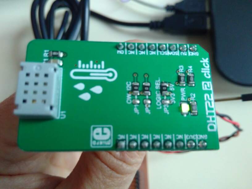
Prior to make additional PCB boards, I want to test the DHT22 v2 click sensor by connecting it directly on the main board:
DHT22 2 click
The DHT222 click from Mikroelektronika is a shield for the CM2322 temperature and humidity sensor from ASAIR, with a temperature range of -40~+80°C and a humidity range of 0~99%RH, and a temperature accuracy of ± 0.3 C (25 C), the precision of humidity of ± 2%RH (30~90%RH).
The schematic of the DHT22 2 is illustrated below:

The integrated microcontroller of the CM2322 provides compensation and calibration as well as a 1-wire and I2C interface.
It is nearly impossible to find information on the CM2322 sensor, so I first wanted to try to apply the Arduino libraries for the DHT22 (based on an AM2302 sensor). This requires to use the DHT 222 in 1-wire mode.
Therefore, at the hardware level, I have to:
- change the jumper on the DHT222 to use the 5V power supply (default is set to 3.3V power supply)
- connect the SCL line to ground (to avoid removing the jumpers, set to I2C position by default)
- connect the SDA pin on any digital pin of the ATmega, e.g. pin 9 (PD5)
- connect the 5V and GND pins of the DHT222 to 5V and GND pins on main board.
On the software level, I use in first instance the Arduino IDE and the sketch DHTTester, with sensor connected pin 9 on the microcontroller. Through the FTDI connector, the Serial monitor embedded in the Arduino IDE is available to display the data.
In 1-wire protocol, the CM2322 switches from Sleep to High Speed mode when the microcontroller host (MCU) sends a start signal (pulls the data bus SDA low by at least 800μs). After the host start signal is completed (line released for minimum 20μs), the CM2322 sends a response signal (pulls the data bus SDA low by at least 800μs))and sends 40Bit on the data bus SDA serially. The data sent is : the high byte of humidity, the low byte of humidity, the high byte of temperature, the low byte of temperature, the checksum byte. The sensor goes automatically into sleep mode after completion of the sending, until the next MCU request.
This is illustrated below:

// Example testing sketch for various DHT humidity/temperature sensors
// Written by ladyada, public domain
// Adapted by Greta

// REQUIRES the following Arduino libraries:
// - DHT Sensor Library: https://github.com/adafruit/DHT-sensor-library
// - Adafruit Unified Sensor Lib: https://github.com/adafruit/Adafruit_Sensor

#include "DHT.h"

#define DHTPIN 5     // ARDUINO (!) Digital pin connected to the DHT sensor

#define DHTTYPE DHT22   // DHT 22  (AM2302), AM2321, CM2322 in 1-wire mode

// Connect GND pin and SCL pin of the DHT222 click to GROUND
// Connect 5V pin of the DHT222 click to +5V (VCC)
// Connect SDA pin 2 of of the DHT222 click to whatever your DHTPIN is

// Initialize DHT sensor.

DHT dht(DHTPIN, DHTTYPE);

void setup() {
  Serial.begin(115200);
  Serial.println(F("DHT222 in 1-wire mode test!"));

  dht.begin();
}

void loop() {
  // Wait a few seconds between measurements.
  delay(2000);

  // Reading temperature or humidity takes about 250 milliseconds!
  // Sensor readings may also be up to 2 seconds 'old' (its a very slow sensor)
  float h = dht.readHumidity();
  // Read temperature as Celsius (the default)
  float t = dht.readTemperature();
  // Read temperature as Fahrenheit (isFahrenheit = true)
  float f = dht.readTemperature(true);

  // Check if any reads failed and exit early (to try again).
  if (isnan(h) || isnan(t) || isnan(f)) {
    Serial.println(F("Failed to read from DHT sensor!"));
    return;
  }

  // Compute heat index in Fahrenheit (the default)
  float hif = dht.computeHeatIndex(f, h);
  // Compute heat index in Celsius (isFahreheit = false)
  float hic = dht.computeHeatIndex(t, h, false);

  Serial.print(F("Humidity: "));
  Serial.print(h);
  Serial.print(F("%  Temperature: "));
  Serial.print(t);
  Serial.print(F("°C "));
  Serial.print(f);
  Serial.print(F("°F  Heat index: "));
  Serial.print(hic);
  Serial.print(F("°C "));
  Serial.print(hif);
  Serial.println(F("°F"));
}
The setup is the following:

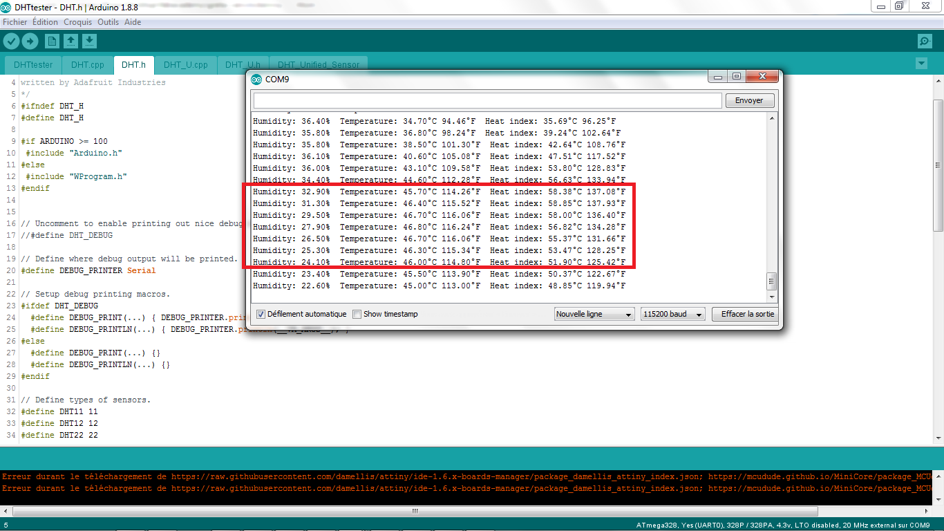
Here is the result, when blowing on the sensor to increase humidity:

Here is the result, when warming the sensor up by means of a lighter:
Update 10 may 2019: I got the CM2322 datasheet directly from the manufacturer. I’m now able to let the sensor work with the I2C protocol.
Datasheet can be found here
To use the I2C protocol:
- connect SDA pin (data line) on pin 27 of the ATmega328P
- connect SCL pin (clock line) on pin 28 of the ATmega328P
- GND and 5V pins unchanged
I intend to use the Arduino WIRE library for I2C control.
Nice explanations on the WIRE library can be found here.
FAILED: The first test made to detect the presence of the CM2322 through the I2C_scanner sketchfrom Arduino fails!!
I got the message that there is no device found, but the SDA signal (yellow) and SCL signal (blue) are present, as illustrated below:


This is due to the fact that the sensor requires specific I2C Modbus protocol, as stated in the datasheet, which is unusual: the sensor doesn’t acknowledge as expected in the I2C protocol when its address is sent over the bus. So given the time constraints, I’ll leave this topic for next assignment (communication).
Note: CM2322 has following i2c (slave) address: 0xB8 : 1011 1000.
7 bit address: 101 1100, 0x5C or 92 in decimal
Support board
Specific board and packaging will be required when using the sensor in real project…
We do not have to forget to add a reverse voltage protection…
I will develop a a support board that can be used with all Mikroelektronica shields: see next assignment (output devices)
Still to do if I had time....
Original idea, still valid, but to be done in the coming weeks, is to design other PCB’s to hold the sensors and to allow supplying the board with a Li-Ion battery…
Ah, and something else I want to do is to get rid of the Arduino dependencies to go back to the AVR definitions!!