8. Computer controlled machining
Assignment
-
[x] group assignment: test runout, alignment, speeds, feeds and toolpaths for your Machines
-
[x] individual assignment: make something BIG
Summary
End of June, I finally start this assignment, making a kneeling rocking chair… I struggle with Fusion360 and its logic, its timeline ( which is a powerful tool, once you manage the program). I used the Kinetic CNC milling machine, I learned that configuration, spindle speed and feedrate included, are important manufacturing parameters to control.
File is available here
Group assignment:
Equipment
We worked this week on different machines.
Amy used the CNC from a friend that owns one at home. It also gave her more time to mill out what she wanted to mill out and the co-students in the ULB lab more time for their assignment.
The machine in the lab is a High-z 1000T, controlled using kinetic-NC.
Mills
Amy used a 4mm flat end mill. She soon figured out that milling a straight line of 40mm did not result in milling 4mm out. Originally it would be 4.60mm, by changing some settings we got to 4.15mm.
@Fablab ULB, we used a 6mm flat end mill.

Christophe made some press-fit tests, and it resulted that the alignment was perfect without adding any correction!


Rounded or square corners?
Concerning the corners, several things must be taken into consideration.
A new thing that we learned was to add little squares in the design. As the mill is round, we wouldn’t have straight corners. Amy added little squares in the design files of 4.5 mm on 2.5 mm so that the corners would be square.
For the press-fit, we would have the same problem. For example, if we have 2 squares fitting, the inner can be perfectly squared (since the mill goes externally), but the outer square can’t (a fillet of the same radius than the mill will appear). We have here 2 solutions:
- As Christophe did above, replace the corners of both pieces by fillets of the same radius, larger than the mill radius.
- Add dogbones, little holes of the same diameter as the mill in the corners, having their circumference coincident with the corner.

Speed/feed rate
Standard this was on 3000, but we changed it to a 1000. While milling out, we could also still change the rate if we thought it could go faster or slower. Makezine has a interesting article about this. And the Carbide 3D (the second CNC milling machine that Amy use) has a library for the rates. This makes it easy to start milling without having to do too much setup. We made tests with the fablab’s CNC, varying the feedrate between 800 and 1200 mm/min using the kinetic-NC interface:

If the feedrate is too high, you can hear it, and the mill will suffers. 1000 mm/min showed to be the best feedrate!
Milling air
As every careful machine operator the first time we started the machine we milled air. We even managed to get some mistakes out of the files because of that. But of course that’s not all. So before we started milling out the big plates, we took the file of the small shelve and milled this one out. It actually went perfect from the first time on.

Safety!
As was stated during the course, making a mistake on the CNC can have serious consequences for the machine, the room but also the people close to it. The machines on which Amy will mill don’t have a protective case. The Shapoko has a plexi plate that keeps most of the flying debris away from people (we corner the machine so that it’s ‘safe’. The BZT doesn’t have any case either, but we’re sitting far enough from it to be safe. The fablab’s CNC has a safety opening on one side: if the doors are open, everything stops!
As we stayed with the machine during milling, I was using protection (on ear and in ear) and also a dust mask.
Dust collection
None of the machines that we worked on this week has a proper dust collection. Not having a dust collection on the machine resulted in getting up every once and a while to check on the machine and vacuum the dust away. Always being careful to be opposite to the mill so that we wouldn’t come into contact.
Individual assignment
Choice of the structure to be made
End of June: I finally take the time to complete my assignment…
My first idea is to make a kneeling chair, looking at several inspiration sources:
- the W-chair by Guntis Zingis
- the Variable Balans Stool by Peter Opsvik
- various kneeling chairs models
- first work of Eva Blaskova during fabacademy 2016.
I first made some rough calculations of the inclination of the seat and knee support looking at various models:

Design with Fusion360
Starting from Eva’s design, I recreate a profile using splines and then remove the original mesh body and save my sketch as a new file.

I also modify the structure to use press-fit construction, adapted to the wood panels available in the lab. Let’s go parametric…
After discussion with Victor, I fixed my design, with only two supports of laminated panel wood, 18mm thick.

I had to struggle with Fusion360, as once a sketch is moved from its original place at creation, there is no way to change the sketch values and parameters. I really had to separate volumes/bodies from the sketches. And duplicate the bodies, using one set for the assembled view, the other one to prepare the g-code for the CNC milling machine.
A tedious job is to ensure non straight corners to press-fit the pieces, by placing dogbones as explained in our group assignment.

File is available here
Once the model is ready, let’s go to the manufacture tab to prepare the fabrication (g-code) file.
Let’s create a new Setup to define the tool (flat end mill 3mm) and the stock (made from a body in Fusion 360).
-
2D CONTOURGEOMETRY: we define the contours (frame and slots) to be cut, and creation of tabs to support the piece while reaching the end of the milling.
HEIGHTS are given as follows: * bottom: stock bottom with an offset of -0.2mm * top: select the top surface of the stock ( which is 18mm thick) * feed: offset of 5mm from top height * retract: 5mm from stock top * clearance: 10mm from retract height
PASSES * Multiple Depths with a stepdown of 2mm (rough) * No stock to leave, no Smoothing, no Optimizations
We then generate the toolpath and simulate the complete milling process through (ACTIONS → Simulate). Once the simulation is correct, we can, we can generate the Gcode file (ACTIONS → Post Process), e.g. convert the machine independent cutter location data into machine-specific NC code. Therefore, we need to load the Kinetic postprocessing configuration file into Fusion360 (file kinetic-nc.ps) to be found on the controlling PC of the CNC.
Milling with the Kinetic CNC machine
On the controlling PC, we need to configure the CNC prior to launch the milling Process
Jog setup
Zeroting the machine in X Y: click on go to park position, take care to be be in G54 workpiece offset mode (right panel), move the milling head above the corner of the stock (by means of the left panel with arrows, controlling the speed from continuous to steps of 0.01mm)
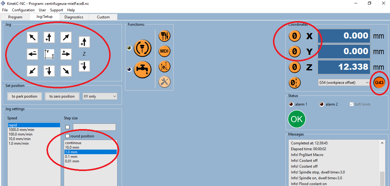
Once the position is correct, click on the “0” button for X and Y in the right coordinates panel.
Custom
To zero the machine in Z, we use the mobile button sensor that we place under the milling head, and we launch the tool Zero finder.... No other operation is needed afterwards: the Z-zero is fixed at stock top (DO NOT click on the “0” button for Z anymore!).
Take care to have the G43 button activated in the coordinates panel.
The maximum available surface of our CNC is 600mm x 1000mm. This configuration makes it difficult to mill two big pieces together. So I had to separate the two side profiles…
A first attempt to configure the CNC went wrong: the structure was outside the milling available surface.

We finally succeeded to place the structure properly:

And the result of the milling of the two profiles is here:

The supporting structures will be done as soon as I’ve replaced the mill: I broke it…

Mill replaced, same diameter (3mm) but shorter… Here we go again.
Two strange issues encountered this time:
- FIRE started while milling the slot on the seat plate,
- The whole panel moved during milling, the seat plate, although it was correctly fixed, leading to misalignment of two slots…
No real explanation to these two problems, or maybe the fact that I didn’t put tabs on the small pieces ?
And definitely, safety is one important point to be considered!

One interesting point to note is that using a shorter mill - same diameter, the fit is much more better!!
Here are finally the results:


Conclusion: I can seat on my chair, but improvements are needed!!

Still to do if I had time....
Add reinforcing support to reduce the lateral movement of the two profiles, and make bigger kneeling chair for taller guys!!