9. Embedded programming
Assignment
- [x] individual assignment:
- read a microcontroller datasheet
-
program your board to do something, with as many different programming languages and programming environments as possible
-
[x] group assignment:
compare the performance and development workflows for other architectures
Summary
This week, I * used my HelloBoard made in week07 to reprogram it to use the added LEDS and button. * prepare myself to use the ATmega328P to use in my final project, by looking at its datasheet, and programming commercial products with this new microcontroller.
Files are available here
Individual assignment
Notes and Introduction
Let’s start analyzing and summarizing a microcontroller datasheet, namely the ATMega328p datasheet, available here
Actually, in a full project, this is the first step, prior to start making the schematic and PCB layout…
Analysis of a microcontroller datasheet
Introduction
Really synthetic but crucial information about the chip: The ATmega48A/PA/88A/PA/168A/PA/328/P is a low power, CMOS 8-bit microcontrollers based on the AVR® enhanced RISC architecture
Low power: interesting for portable devices powered through batteries for example.
CMOS: Complementary metal oxide semi-conductor: fabrication technology for the electronic components
RISC architecture: data and program are stored in separate memories…
Features
This is an short overview/summary of the features of the microcontroller, providing important information. e.g., the ATMega is
Pin configuration and description
The pins configuration depends on the package. In order to be able to handsolder, we choose the TQFP package:
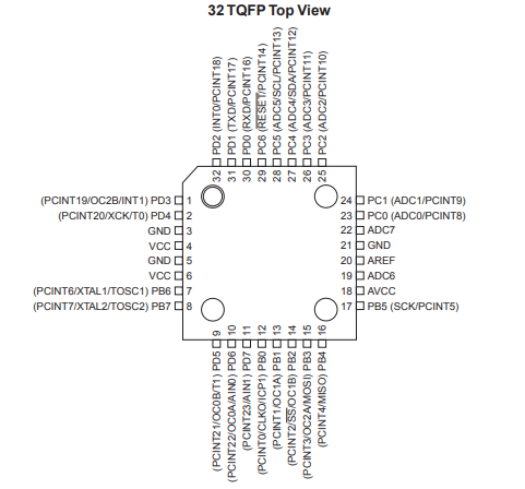
The datasheet gives then some global description on the functionality of all pins. More detailed data will be found later in in separate sections.
Block diagram, AVR CPU core
The block diagram and AVR CPU Code provide detailed information on the architecture of the microcontroller, and on the structure of the control process unit (CPU), the core of the system!
This detailed information is not needed at this stage, and we’ll come back when more information may be needed on interrupt management.
What is interesting is next topic:
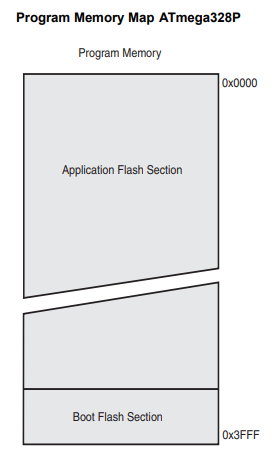
AVR memories
- The ATmega328P contains 32Kbytes On-chip In-System Reprogrammable Flash memory for program storage.
For software security, the Flash Program memory space is divided into two sections, Boot Loader Section and Application Program Section
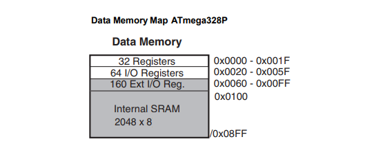
- The Volatile part of the data memory (SRAM: Static Random Access Memory) is as follows:
- The non-volatile part of the data Memory, the EEPROM (Electrically Erasable Programmable Read-Only Memory) is used to store relatively small amounts of data but allowing individual bytes to be erased and reprogrammed.
The ATmega328P contains 1Kbyte of data EEPROM memory. It is organized as a separate data space, in which single bytes can be read and written.
Both the Flash and EEPROM memory arrays can be programmed using the serial SPI bus while RESET is pulled to GND. The serial interface consists of pins SCK, MOSI (input) and MISO (output). After RESET is set low, the Programming Enable instruction needs to be executed first before program/erase operations can be executed.
This is exactly what has been done in previous weeks....
Besides the ICSP programming mode, the Boot Loader Support in the ATmega328p provides a “self-programming” mechanism for downloading and uploading program code by the MCU itself. in other words, the program code within the Boot Loader section has the capability to write into the entire Flash, including the Boot Loader memory, modifying or even erasing itself!
This feature allows flexible application software updates controlled by the MCU using a Flash-resident Boot Loader program. The Boot Loader program can use any available data interface and associated protocol to read code and write (program) that code into the Flash memory, or read the code from the program memory!
The size of the Boot Loader memory is configurable with fuses and the Boot Loader has two separate sets of Boot Lock bits which can be set independently. This gives the user a unique flexibility to select different levels of protection.
What is a fuse?
There are 3 bytes of non-volatile storage called the fuses. The fuses determine how the chip will act, whether it has a bootloader, what speed and voltage it likes to run at, etc. Note that despite being called ‘fuses’ they are re-settable and don’t have anything to do with protection from overpowering (like the fuses in a home).
How to change fuse bits in a ATmega328p is explained here.
Here is a tool to help programming the fuses.
In addition, there is the I/O memory and the register memory, that are storage locations internal to the processor, used during the process of exchanging data between I/O devices and the main processing unit.
System Clock and Clock Options
Selecting the correct clock is of paramount importance in the correct functioning of a microcontroller. There is a clock source, giving the cadence of every operation inside the MCU: speed of the CPU operations, baud rate of serial-communication signals, the amount of time needed to perform an analog-to-digital conversion, and so on…
There are quite a few ways to generate a clock signal for a microcontroller, each having its drawbacks and advantages (source: https://www.maximintegrated.com/en/app-notes/index.mvp/id/2154)
The optimal clock source for a particular microcontroller application is determined by a combination of factors including accuracy, cost, power consumption, and environmental requirements. The following table summarizes the common oscillator circuit types discussed here, together with their strengths and weaknesses.
Table 1. Performance Comparison of Clock Source Types
| Clock Source | Accuracy | Advantages | Disadvantages |
|---|---|---|---|
| Crystal | Medium to high | Low cost | Sensitive to EMI, vibration, and humidity. Complex circuit impedance matching. |
| Crystal Oscillator Module | Medium to high | Insensitive to EMI and humidity. No additional components or matching issues. | High cost; high power consumption; sensitive to vibration; large packaging. |
| Ceramic Resonator | Medium | Lower cost | Sensitive to EMI, vibration, and humidity. |
| Integrated Silicon Oscillator | Low to medium | Insensitive to EMI, vibration, and humidity. Fast startup, small size, and no additional components or matching issues. | Temperature sensitivity is generally worse than crystal and ceramic resonator types; high supply current with some types. |
| RC Oscillator | Very low | Lowest cost | Usually sensitive to EMI and humidity. Poor temperature and supply-voltage rejection performance. |
The choice of a 20MHz is explained in the @fabacademy documents
The datasheet explains how to set the Flash Fuse bits for the different available clock sources.
We choose here to use an external oscillator (resonator). The clock from the selected source is input to the AVR clock generator, and then routed to the appropriate modules.
The resonator used here is a 20MHz resonator (capacitors included in the same chip as the crystal), requiring to set the fuses CKSEL3…1 to 011.
Important note in the datasheet: If the crystal frequency exceeds the specification of the device (depends on VCC), the CKDIV8 Fuse can be programmed in order to divide the internal frequency by 8. It must be ensured that the resulting divided clock meets the frequency specification of the device.
Power Management and Sleep Modes
Sleep modes enable the application to shut down unused modules in the MCU, thereby saving power. The AVR provides various sleep modes allowing the user to tailor the power consumption to the application’s requirements.
There are six different sleep mode, to be set through registers. We’ll look at this later on…
System Control and Reset
During reset, all /O Registers are set to their initial values, and the program starts execution from the Reset Vector. For ATmega328P the instruction placed at the Reset Vector must be a JMP – Absolute Jump – instruction to the reset handling routine
The ATmega48A/PA/88A/PA/168A/PA/328/P has four sources of reset: * Power-on Reset. The MCU is reset when the supply voltage is below the Power-on Reset threshold (VPOT). * External Reset. The MCU is reset when a low level is present on the RESET pin for longer than the minimum pulse length. * Watchdog System Reset. The MCU is reset when the Watchdog Timer period expires and the Watchdog System Reset mode is enabled. * Brown-out Reset. The MCU is reset when the supply voltage VCC is below the Brown-out Reset threshold (VBOT) and the Brown-out Detector is enabled.
Interrupts
Interrupts are basically events that require immediate attention by the microcontroller. When an interrupt event occurs the microcontroller pause its current task and attend to the interrupt by executing an Interrupt Service Routine (ISR) at the end of the ISR the microcontroller returns to the task it had pause and continue its normal operations. Nice tutorial available here
I/O-Ports
Ports as General Digital I/O The ports are bi-directional I/O ports with optional internal pull-ups.
Alternate Port Functions Most port pins have alternate functions in addition to being general digital I/Os.
Timers and Counters
The AVR has an interesting circuit, as shown below. This circuit has 2 inputs and one output:
 .
.
If you tie it into the Tn pin it will count the pulses on the pin (this is referred to as a counter on the datasheet).
If you tie it into the AVRs internal(or external) clock you now have a timer.
If you tie the counter to the output you will get an Pulse Width Modulator signal on the OCnx pin.
The ATmega328P has several timers/counters: * 8-bit Timer/Counter0 with PWM * 16-bit Timer/Counter1 with PWM * Timer/Counter0 and Timer/Counter1 Prescalers * 8-bit Timer/Counter2 with PWM and Asynchronous Operation
The datasheet and the application Note AVR130: Setup and Use of AVR Timers provide more information on how to use the timers/counters.
SPI – Serial Peripheral Interface
The Serial Peripheral Interface (SPI) allows high-speed synchronous data transfer between the ATmega328P and peripheral devices or between several AVR devices.
USART
The Universal Synchronous and Asynchronous serial Receiver and Transmitter (USART) is a highly flexible serial communication device.
Analog-to-Digital Converter
The ATmega328P features a 10-bit successive approximation ADC. The ADC is connected to an 8-channel Analog Multiplexer which allows eight single-ended voltage inputs constructed from the pins of Port A. The single-ended voltage inputs refer to 0V (GND). The ADC contains a Sample and Hold circuit which ensures that the input voltage to the ADC is held at a constant level during conversion.
The ADC has a separate analog supply voltage pin, AVCC. AVCC must not differ more than ±0.3V from VCC. Internal reference voltages of nominally 1.1V or AVCC are provided On-chip. The voltage reference may be externally decoupled at the AREF pin by a capacitor for better noise performance.
The ADC converts an analog input voltage to a 10-bit digital value through successive approximation. The minimum value represents GND and the maximum value represents the voltage on the AREF pin minus 1 LSB.
Summaries of several characteristics
The ATmega328P datasheet ends with a summary of the available registers and a summary of the instructions set. The latest are the instructions, written in machine language, that the MCU understands and is able to execute.
Programming my PCB
In week07, I added two leds and a push button on the original echo hello-world board.
So, this week, I’ll program the board with following objectives:
- Control both leds (green, on pin PA2 and red on pin PA3 ) from the keyboard, through the FTDI connector by entering G (or g) to toggle the green led, and R (or r) to toggle the red led. This functionality is handled through an interrupt routine (ISR).
- Control both leds together from the push button and send message to terminal. Direct polling or interrupt may used for the button.
WinAVR + FabtinyISP
In first instance, I use WinAVR on my Windows 7 PC, starting from Neil’s helloboard program....
We use the same procedure as described in week05
I first added the pin definition adapted to my board:
//Pins definitions

  #define serial_port PORTA
  #define serial_direction DDRA
  #define serial_pins PINA
  #define serial_pin_in (1 << PA0)
  #define serial_pin_out (1 << PA1)

  #define led_port PORTA
  #define led_direction DDRA
  #define led_pins PINA
  #define led_pinG (1 << PA2)
  #define led_pinR (1 << PA3)
  #define ledG PA2
  #define ledR PA3

  #define button_port PORTB
  #define button_direction DDRB
  #define button_pins PINB
  #define button_pin (1 << PB2)
  #define button PB2

//define interrupt from serial port (keyboard) & button

#define serial_interrupt (1 << PCIE0)
#define serial_interrupt_pin (1 << PCINT0)
// Pin Change Interrupt 0, Source 0. The PA0 pin can serve as an external interrupt source for pin change interrupt 0.

#define button_interrupt (1 << PCIE1)
#define button_interrupt_pin (1 << PCINT10)
//PCINT10:Pin Change Interrupt 1, Source 10.The PB2 pin can serve as an external interrupt source for pin change interrupt 1.
In the main program, interruptions need to be activated:
//
// set up pin change interrupt on input pin
//

set(GIMSK, serial_interrupt); // Enable serial_interrupt_pin (PA0) Change Interrupts
set(PCMSK0, serial_interrupt_pin);  //Use serial_interrupt_pin (PA0) as interrupt pin

set(GIMSK, button_interrupt); // Enable button_interrupt_pin (PB2) Change Interrupts
set(PCMSK1, button_interrupt_pin);  //Use button_interrupt_pin (PB2) as interrupt pin

sei();  //Enable interrupts
Handling of interruption by introducing character through the keyboard is performed through PCINT0interrupt vector, as follows:
ISR(PCINT0_vect)  {
   //
   // keyboard interrupt handler
   //
   static char chr;

   get_char(&serial_pins, serial_pin_in, &chr);

   put_string(&serial_port, serial_pin_out, "Hello, what do you want? ");
   put_char(&serial_port, serial_pin_out, 13); // carriage return
   put_char(&serial_port, serial_pin_out, 10); // new line

   put_string(&serial_port, serial_pin_out, "To toggle the red LED, type R");
   put_char(&serial_port, serial_pin_out, 13); // carriage return
   put_char(&serial_port, serial_pin_out, 10); // new line

   put_string(&serial_port, serial_pin_out, "To toggle the green LED, type G");
   put_char(&serial_port, serial_pin_out, 13); // carriage return
   put_char(&serial_port, serial_pin_out, 10); // new line


   if (chr == 82 || chr == 114) {   //character R or r
     toggle(led_port, led_pinR);      //change the led status to blink it
     put_string(&serial_port, serial_pin_out, "RED LED!");
     put_char(&serial_port, serial_pin_out, 13); // carriage return
     put_char(&serial_port, serial_pin_out, 10); // new line
     _delay_ms(200);
    }

    if (chr == 71 ||chr == 103) {   //character G or g
     toggle(led_port, led_pinG);      //change the led status to blink it
     put_string(&serial_port, serial_pin_out, "GREEN LED!");
     put_char(&serial_port, serial_pin_out, 13); // carriage return
     put_char(&serial_port, serial_pin_out, 10); // new line
     _delay_ms(200);
    }
 }
Functionality of the button is first introduced at the level of the main loop. Code is based on Nico code:
if bit_test(button_pins, button) {     //test wether the button is pressed : if not... (level it then high)
  clear(led_port, led_pinR);        //if not, light the led off
  clear(led_port, led_pinG);
  if(was_active){                   //if it was pressed during the last loop, put an "exit message"
    //clean terminal, found on  https://stackoverflow.com/questions/10105666/clearing-the-terminal-screen
    put_char(&serial_port, serial_pin_out, 27);
    put_string(&serial_port, serial_pin_out, "[2J");
    put_char(&serial_port, serial_pin_out, 27);
    put_string(&serial_port, serial_pin_out, "[H");
    put_string(&serial_port, serial_pin_out, "Good bye - no operation!");

    put_char(&serial_port, serial_pin_out, 13); // carriage return
    put_char(&serial_port, serial_pin_out, 10); // new line
    was_active=0; //disable the was_active flag
    }
}
else {       //if the button was pressed
    toggle(led_port, led_pinR);      //change the led status to blink it
    toggle(led_port, led_pinG);      //change the led status to blink it
    put_string(&serial_port, serial_pin_out, "Stop using the button! Use the keyboard!");
    put_char(&serial_port, serial_pin_out, 13); // carriage return
    put_char(&serial_port, serial_pin_out, 10); // new line
    _delay_ms(500);   //wait a bit before going to the next step
    was_active=1;     //change the was_active flag so that an exit message will be send on button release
  }
The complete files are available here.
To program my PCB, I use the same hardware setup as in week07
After running, in Programmer’s Notepad (WInAVR), make all to check the .hex file, and make program to load it to the ATtiny84 board, we can disconnect the programmer from the board, but we need the communication with the PC. Fuses were already programmed in week05, it’s not necessary to reprogram them again…
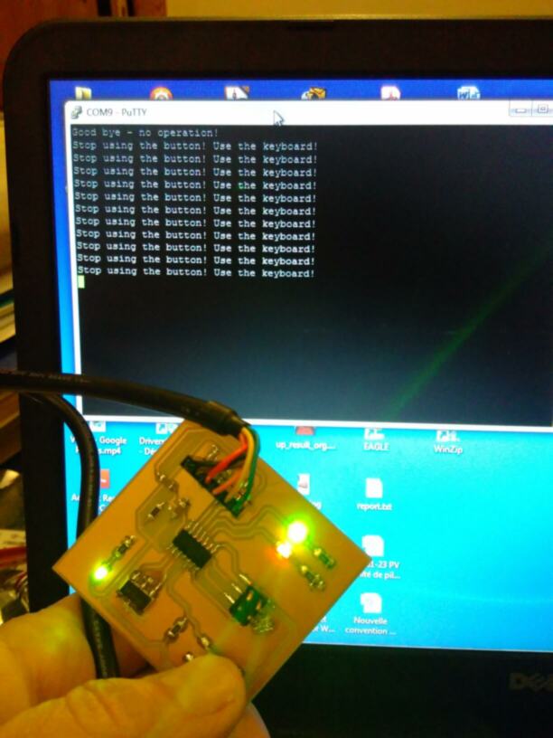
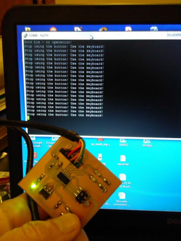
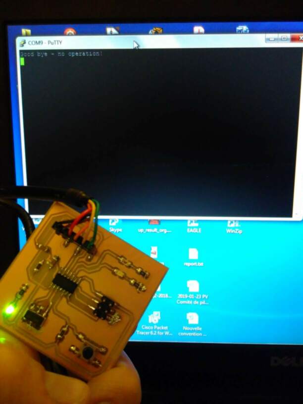
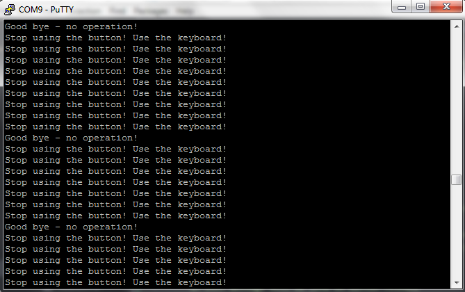
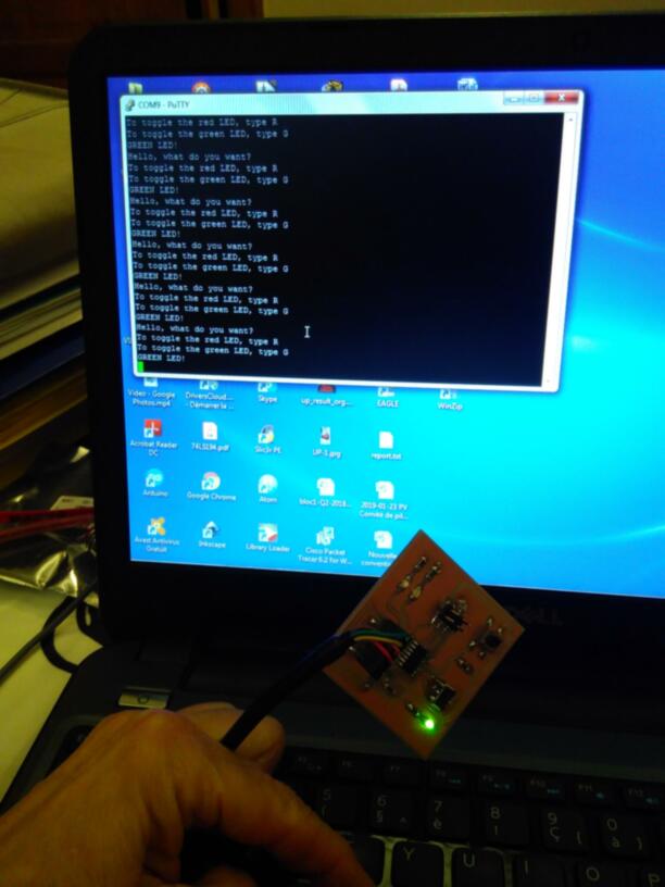
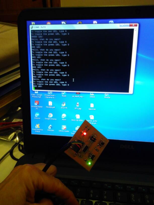
Both control through the terminal and through the button are correctly performed, a illustrated below:
Pushing the button toggles both leds together, while a message is sent to the PC: “Stop using the button! Use the keyboard!”
| leds on | leds off |
|---|---|
 |
 |
| no action |
|---|
 |
| screen |
|---|
 |
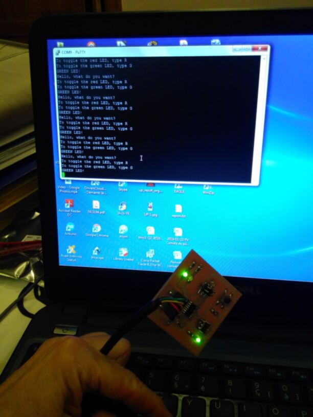
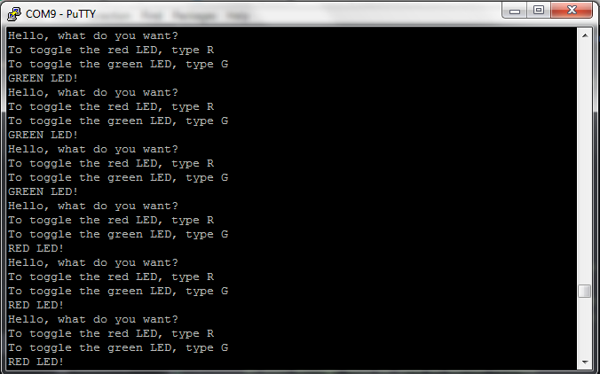
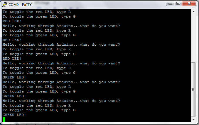
When using the keyboard, “G” or “g” toggles the green led, “R” or “r” toggle the red led, while the PCB send a string to hte PC to indicate which led is toggled (“GREEN LED!” or “RED LED!”) and remembering the user to use the correct strokes to control the leds.Any other key hasno effect…
| green led on | green led off |
|---|---|
 |
 |
| red led on | red led off |
|---|---|
 |
 |
| screen |
|---|
 |
The issue I still need to solve, is that once the keyboard has been used, the control through the button seems not to work anymore! Looks like the system does not come out of the interrupt routine!! To be further investigated!!!
Arduino IDE + Arduino NANO
First of all, be sure to have the ATtiny recognized by the Arduino IDE, by following the steps given in week05. Arduino NANO is recognized by default..
We follow the tutorials given here or here.
First program the Arduino NANO with the example code ArduinoISP. Therefore,
- choose the correct target (Arduino NANO),
- select the serial port to which the Arduino NANO is connected,
- upload the sketch ArduinoISP, without programmer(CTRL+U).
Now the Arduino NANO is nearly ready to be used as programmer…
- adapt the C code previously for the HelloBoard for Arduino: here we can keep the original C program, we just move all definitions to the
void setup() function, and the while (1) becomes now thevoid loop()function. We do not use the definitions specific to Arduino… - choose the target (ATtiny84),
- select the serial port to which the Arduino NANO is connected,
- connect the Arduino board to the ATtiny as follows:
| pin on ICSP connector HelloBoard: | WITH pin on Arduino NANO: |
|---|---|
| pin 1: MISO | pin PB4 (D12) |
| pin 2: VCC | VCC |
| pin 3: SCK | pin PB5 (D13) |
| pin 4: MOSI | pin PB3 (D11) |
| pin 5: RESET | pin PB2 (D10) |
| pin 6: GND | GND |
- Connect a 1 uF capacitor between reset and ground on the Arduino NANO (negative pin of the polarized capacitor goes to ground): it prevents the Arduino NANO from resetting (which starts the bootloader), thus ensuring that the Arduino IDE talks to the ArduinoISP (not the bootloader) during the upload of sketches.
- upload the sketch into the ATtiny84 through the Arduino NANO as programmer (CTRL+SHIFT+U).
Here is the hardware setup, a little bit messy as I do not have the right cables with me at that time… :-):
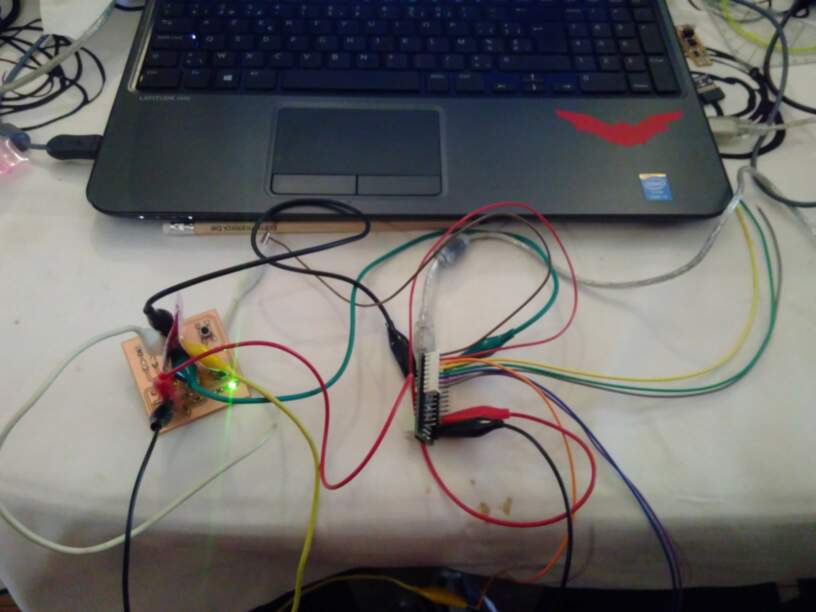
And the result is the same as with the previous setup (WinAVR + FabtinyISP): (I just changed the welcome message…):
Atmel Studio7 + Atmel ICE
TO BE COMPLETED Atmel Studio 7 is a powerful tool to program and even debug on AVR microcontrollers. The Atmel START software helps making some configuration files. In Atmel Studio7.It could even load a Arduino sketch and adapt it!....
But time and life is short, I leave this for later…
Group assignment
We used several workflows to get our board programmed.
Languages:
C: we all programmed our microcontrollers in C. Amy also used blockly a really nice interface allowing diagram coding for C.assembler: Axel also tried assembler, just for fun!
programming in C seems to be clearly the easy way here. However, it still remain very general, and allows to keep a good control and what you want your chip to do!
Programming environment, compiler, and programmer:
Any text editor,avrdude, and afabISPon Linux: Gilles and Christophe used this solution. It requires a makefile to tell arvdude how to program the chip.Any text editor,WinAVR, and afabISPon Windows 7: Greta and Axel tested this solution, similar to the first one but on Windows 7.Arduino IDEand anArduinoon Windows: Greta and Amy tried this solution.Atmel studioand afabISPon Windows: Gilles tried this solution, but did not succeed.Atmel studioand aAtmel commercial programmeron Windows: Greta, Amy and Gilles tried this.
Using avrdude is very efficient and was a good solution, but you need Linux. WinAVR is similar but only works on windows 7. If you want to program using windows, using commercial solutions will be required… It has the drawback to be commercial, but depending on the solution, you will have more possibilities in term of debugging and reading the chip than avrdude or winAVR!
Still to do if I had time....
-
Solve the issue with the interrupt routine
-
Use commercial ATMEL Studio and ICE to program the board
-
Dig into the SPI protocol and analyze the ArduinoISP and the soft downloaded into my programmer during week05.... Let’s dream…