18. Wildcard week
This week I worked on defining the last details of my final project idea and started to getting used to the documentation process. The project that I choose was a composite of 3D printed PLA (Poly-lactic Acid) part and Polyurethane resin (A+B), I demonstrated with it workflows used in the chosen process. Finally I selected and apply suitable materials and processes to create my project.
What is my project?
I was intrigued by the fact that the 3D printed part was no usable for hard work, so I decided to research about how can I improve the resistance of the 3D printed part.
I found on the web a bunch of method that were:
-
Buy special kind of filaments like carbon fiber filled filament.
-
Buy special 3D printer that has a different spool of fiber to reinforce the printed part.
-
Fill the hollowed the 3D printed part with resin and some kind fiber
This is the last method I mentioned and that inspired me.

How I did the project?
How I decided what model to design
If someone wants to tests if this composite is better than the printed one it needs to be with the shape of a standard test specimen.
I choose the ISO 3167 - Multipurpose test specimen that I found in this site: plti.
Scope
ISO 3167 defines a single test specimen that can provide samples for a wide variety of testing. This is a significant difference from ASTM, where multi-cavity molds are often used to provide the variety of test samples for basic physical testing.
Specimen size
The multipurpose test specimen has the basic shape of a tensile dog bone, 150 mm long, with the center section 10 mm wide by 4 mm thick by 80 mm long.
3D modeling with Autodesk Fusion 360
Here you can see the 3D model of the test specimen.
Files of Fusion 360
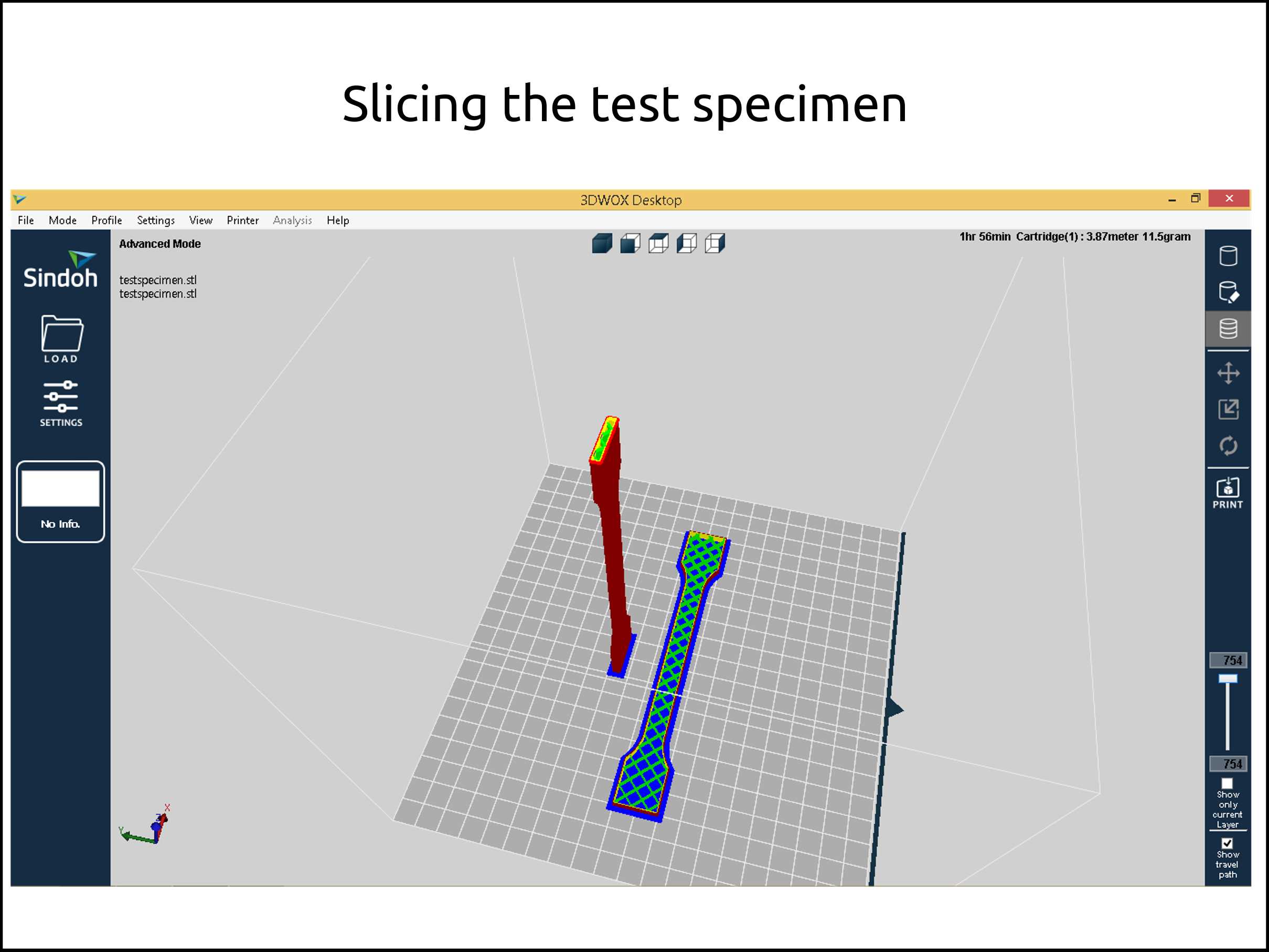
Configuring 3DWOX slicer software
Here I show the two orientation of the test specimen, that was printed using Sindoh 3DWOX1 with these settings:
- Infill: 15%
- Outline: 0.8 mm
- Top/Bottom: 0.0 mm
- Printing speed: 80 mm/s
I printed in two orientation, to know witch one is better.
Files of 3DWOX1 slicer software
Here you have the profile for hollowed parts, gcode and the stl
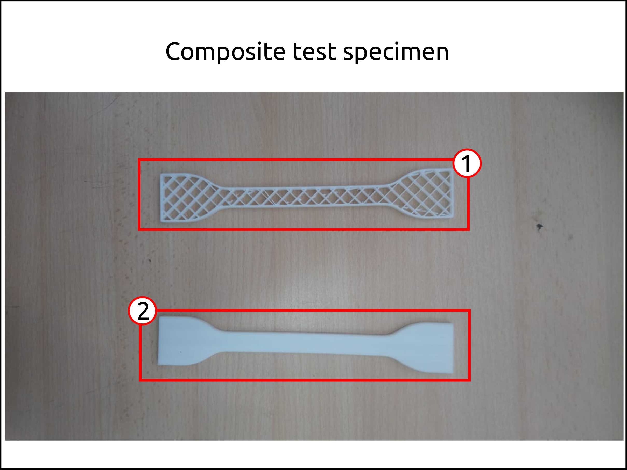
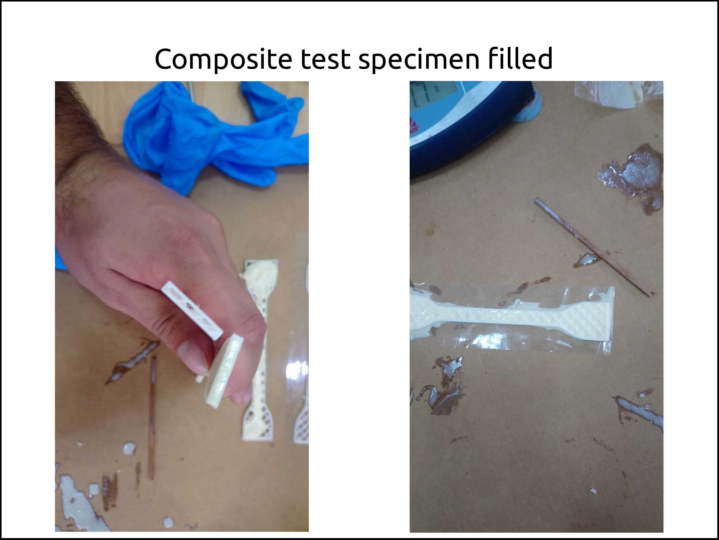
Filling the 3D printed part with Polyurethane
-
This the test specimen that was printed with the horizontal orientation, without the top/bottom.
-
This the test specimen that was printed with the vertical orientation, without the top/bottom.
-
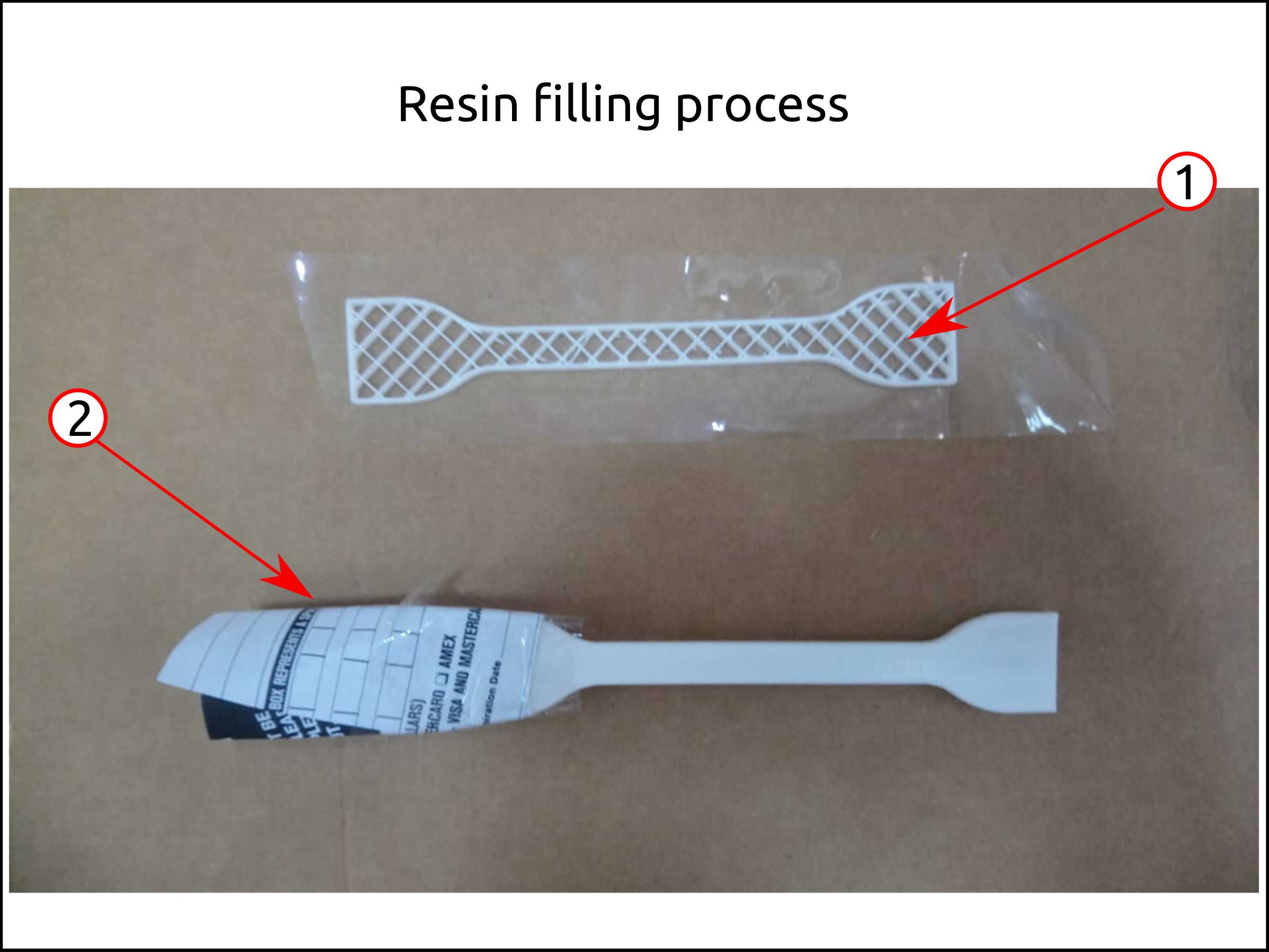
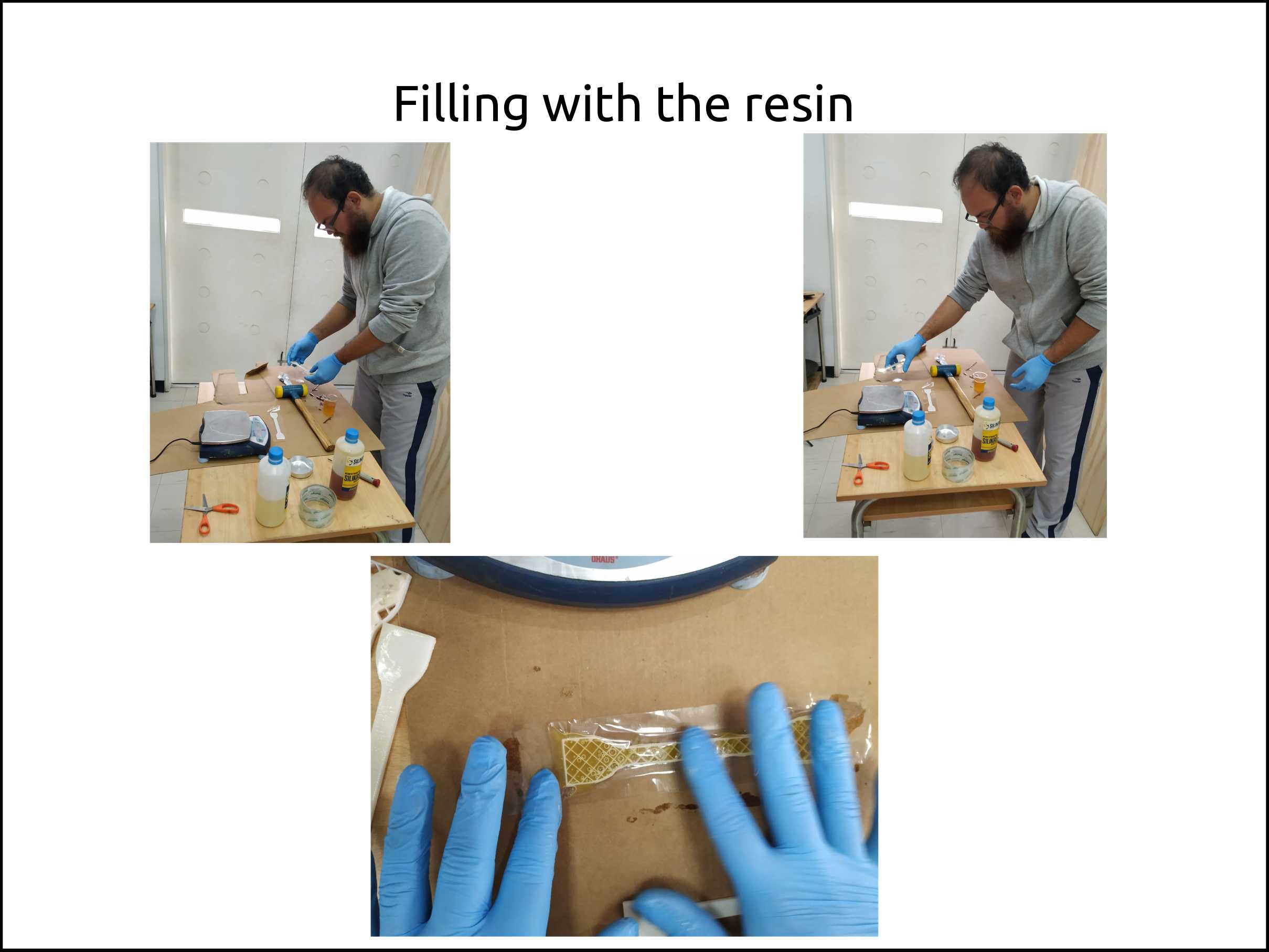
First I closed the holes of the part using scotch tape, in order to fill with the Polyurethane.
-
I used a piece of paper to make a funnel to fill the vertical oriented printed part, and I closed the hole using scotch tape as well.
-
In order to fill the horizontal oriented part I need to place the part on a flat surface.
-
For the vertical oriented part I need to place vertically to fill easily the part.
-
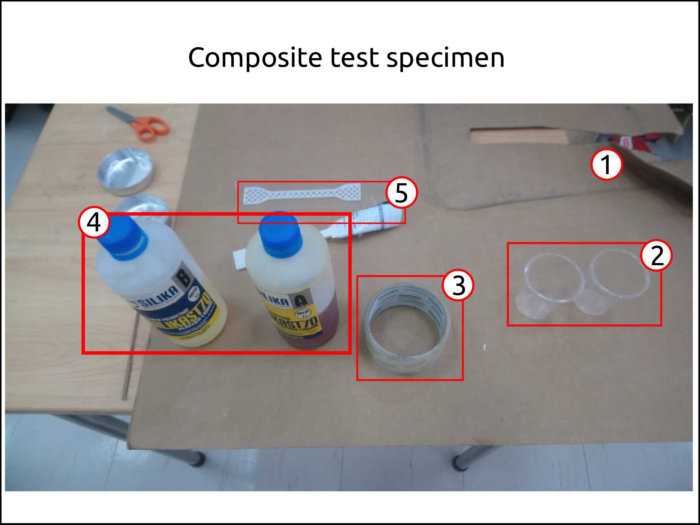
To fill the printed parts we need to prepare the table, protecting the surface using polyethylene bag or cardboard.
-
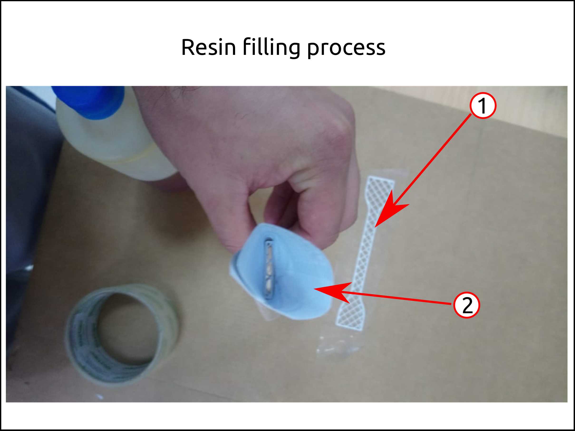
In order to mix the Polyurethane resin we need a plastic cup.
-
To get closet the holes during the resin Filling is necessary scotch tape.
-
The Polyurethane resin has two parts that has to be mixed with 1:1 of ratio.
-
Finally we need the parts that we will fill with the resin.
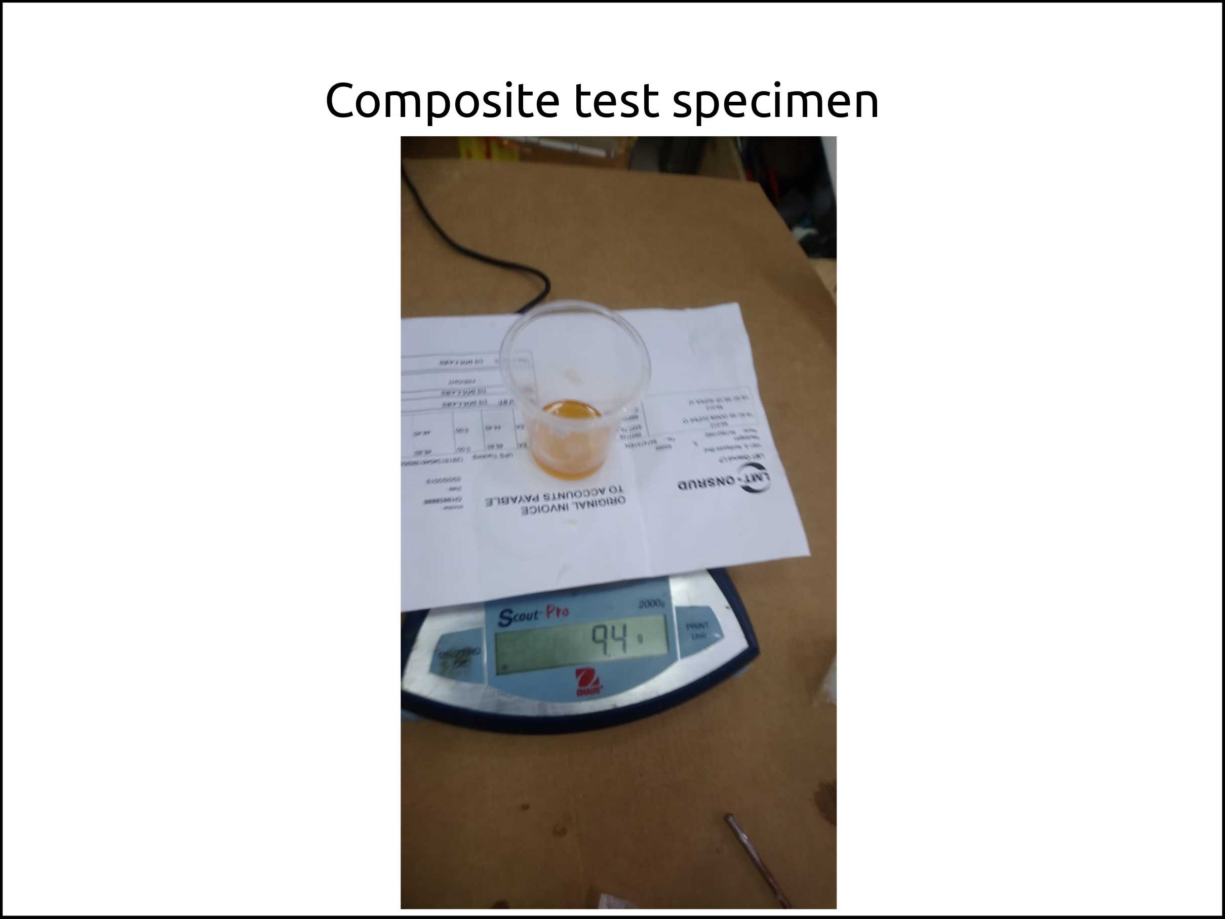
In this case I used a scale to measure the ratio of the resin. You can use a volumetric measure tool as well.
I my first try I could not do it right because I filled first the vertical oriented printed part, and that process was too slow. That was followed for the fast curing of the Polyurethane resin.
So, I re-printed the part and I tried again.
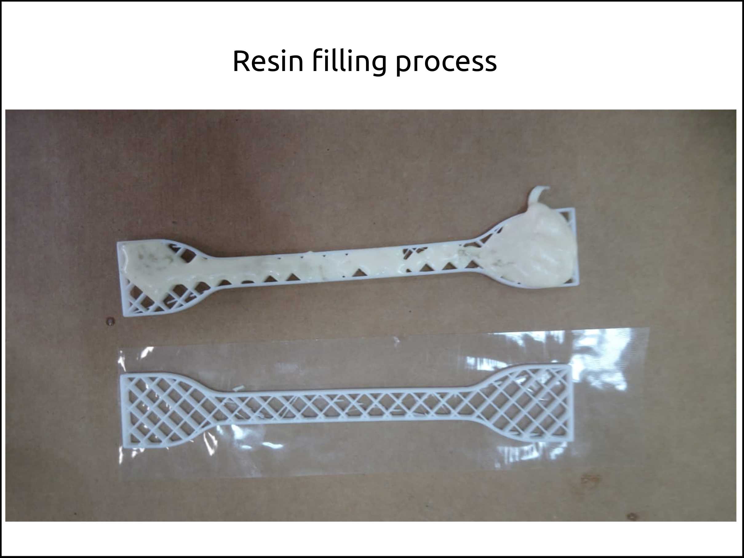
Here we can see the results of the composite. Both the vertical and horizontal oriented printed parts.
Faced problems and solutions working with the composite
Problems
- I prepared too much mixture of resin and the filling process was slow.
Solutions
- I prepared less mixture, for individual filling process.
What I learned this week?
I learned how to install Anaconda and what it is for. I also learned how to install OpenCV, and I started to play with it. I learned about the “JPG” of 3D models, that is the format glTF.