ELECTRONICS PRODUCTION
Software:
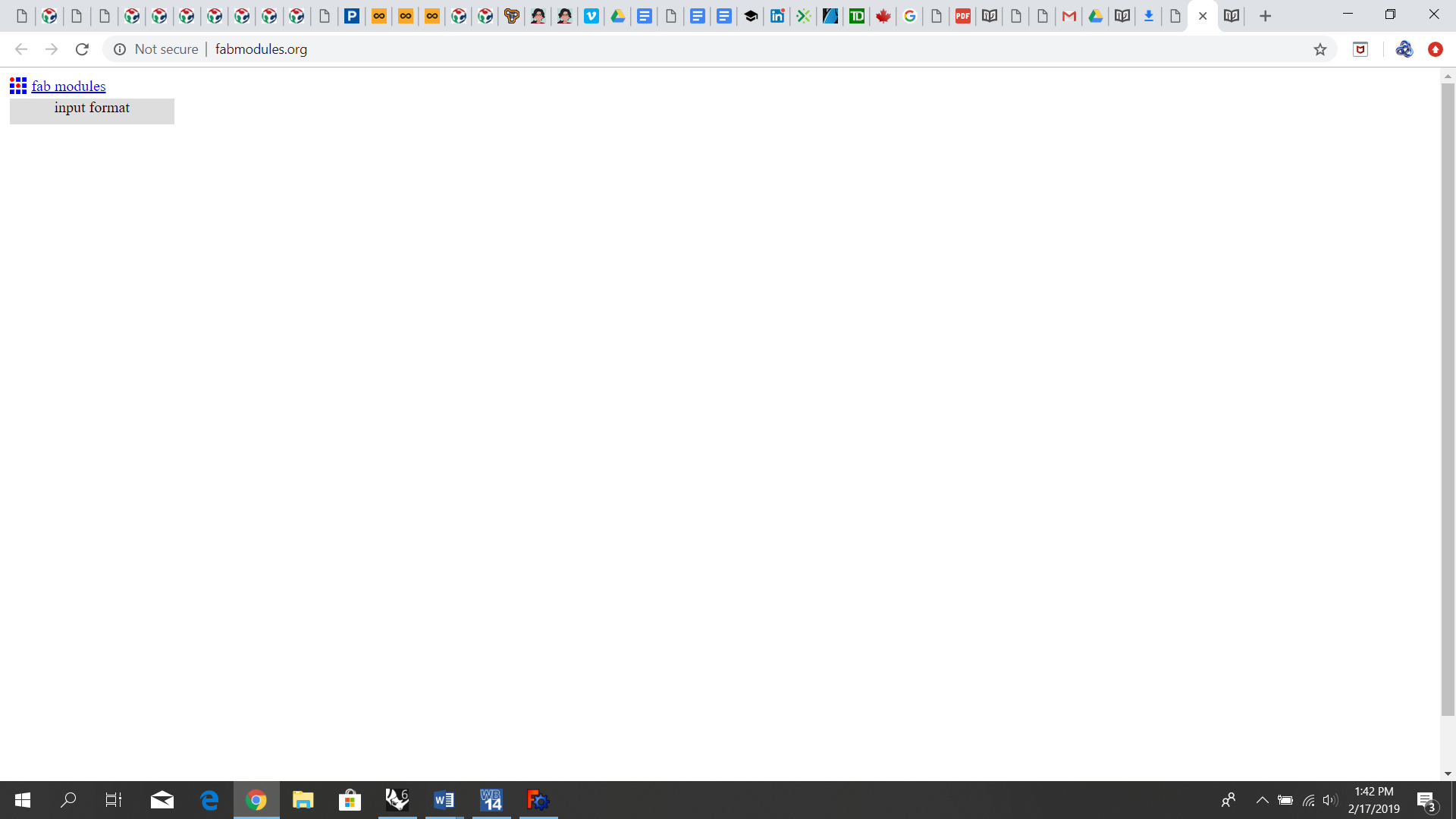
http://fabmodules.org/
Hardware and Machines:
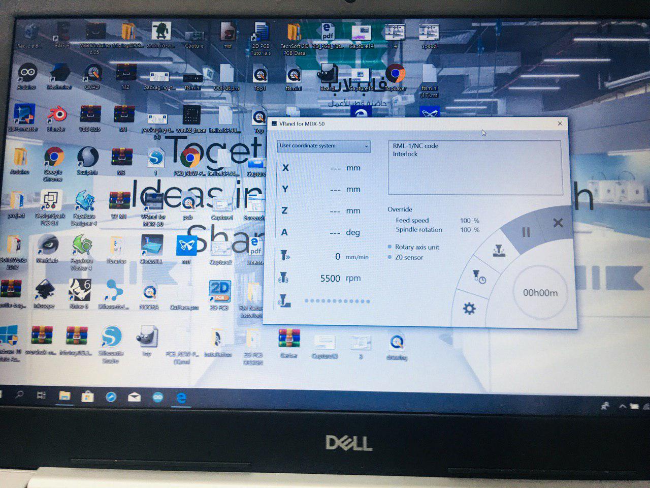
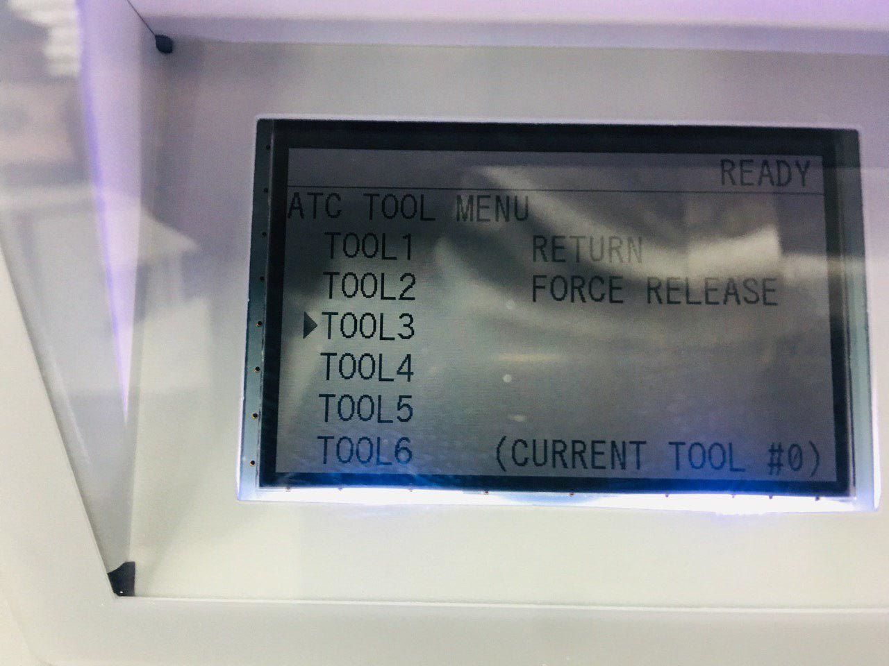
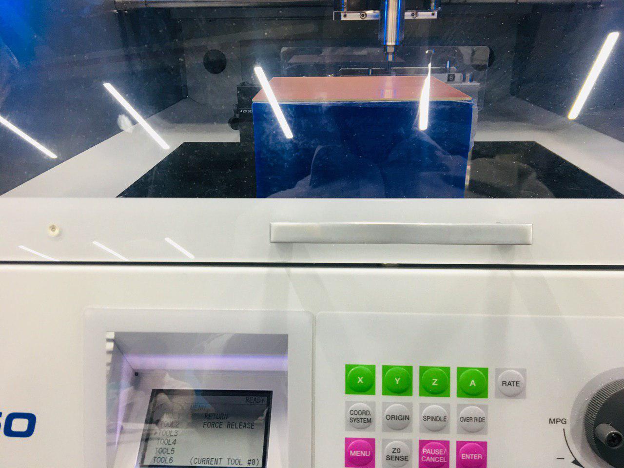
Roland MDX-50
Building the FabTinyISP,soldering the in-circuit programmer and PCB Milling with Roland MDX-50
In this week, we introduced to electronics production techniques in order to build electronic circuits. In electronic production we can produce printed circuit board (PCB) including the PCB itself, soldering the components as well as the programming of the digital electronics. There is many different techniques in electronics production such as surface-mount technology (SMD, etching, sewing, electroplating, milling, fiber laser and vinyl cutter. Also, there are number of PCB materials such as FR1, Aluminum, paper and cardboard. In addition, I learned a great flow work technique for making a PCB as shown in the diagram below:
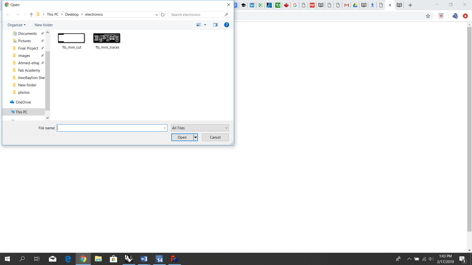
I downloaded the PCB images from the previous tutorial link
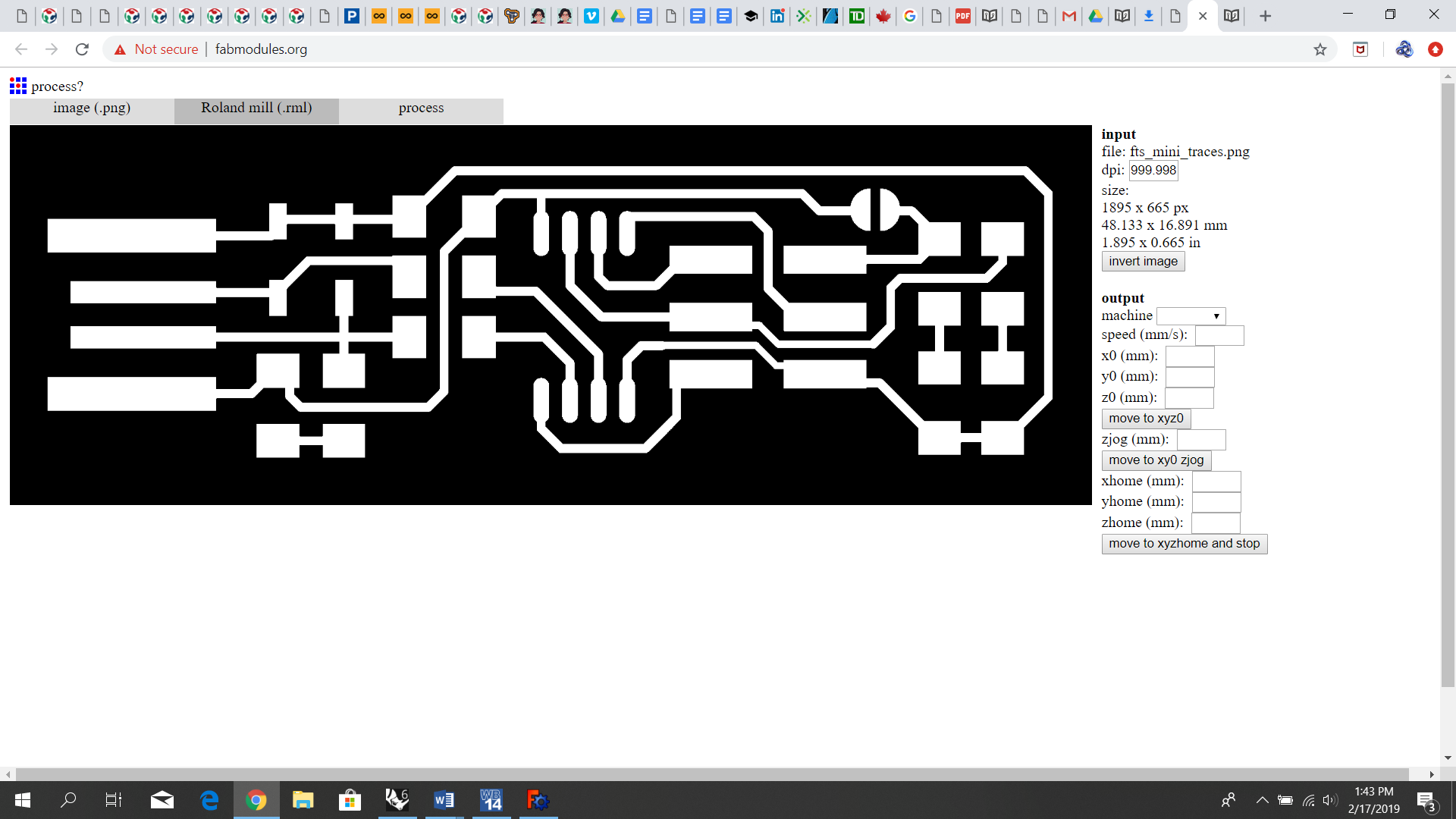
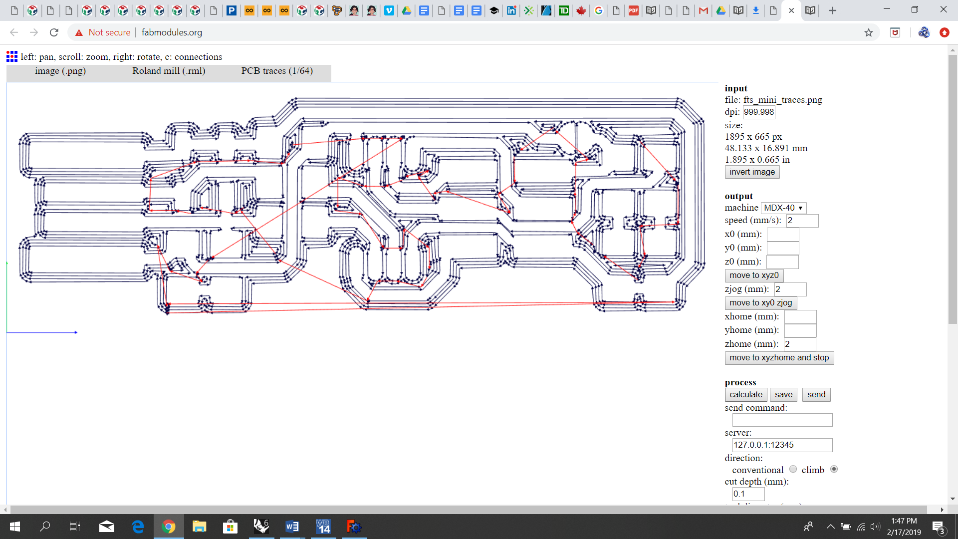
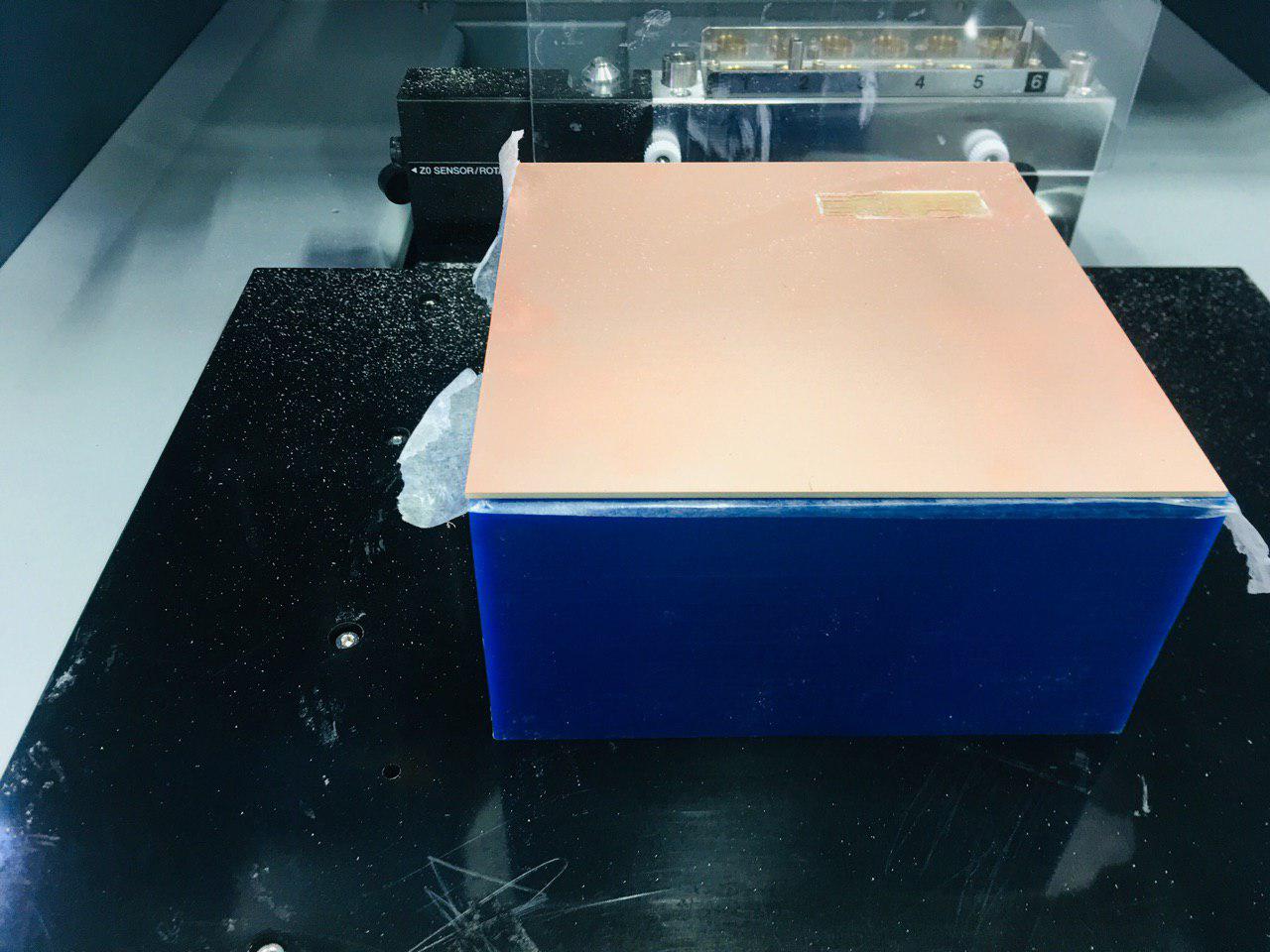
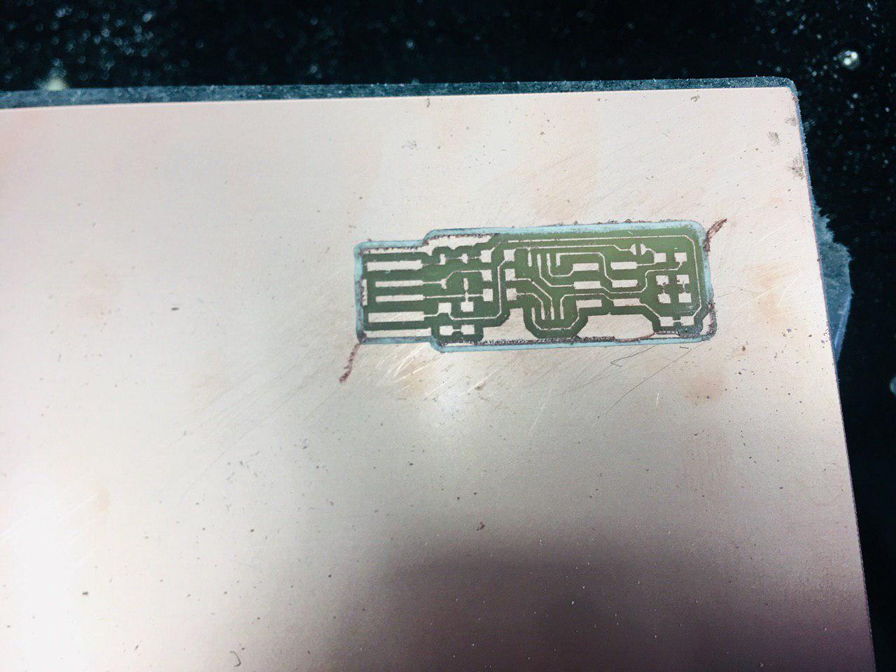
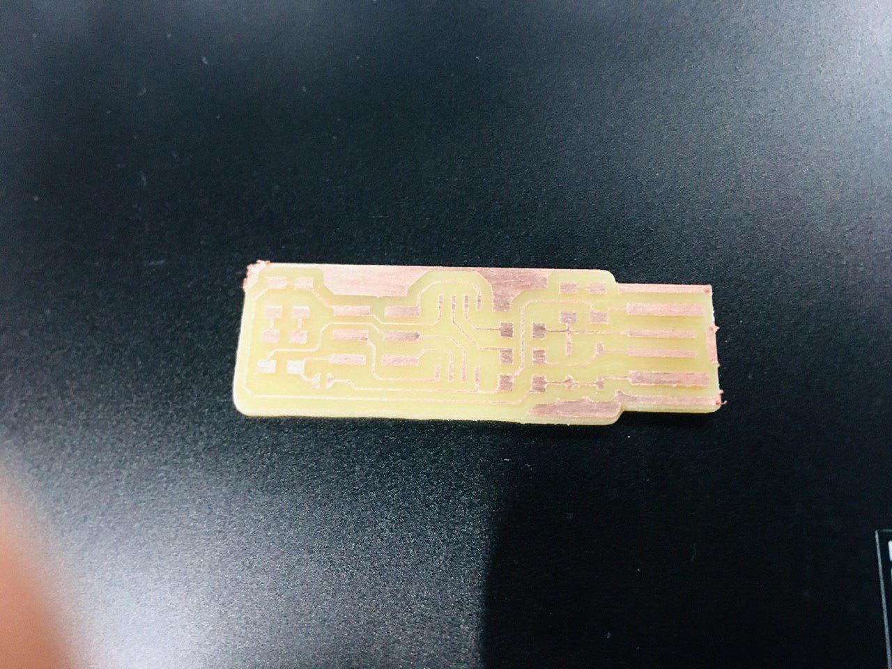
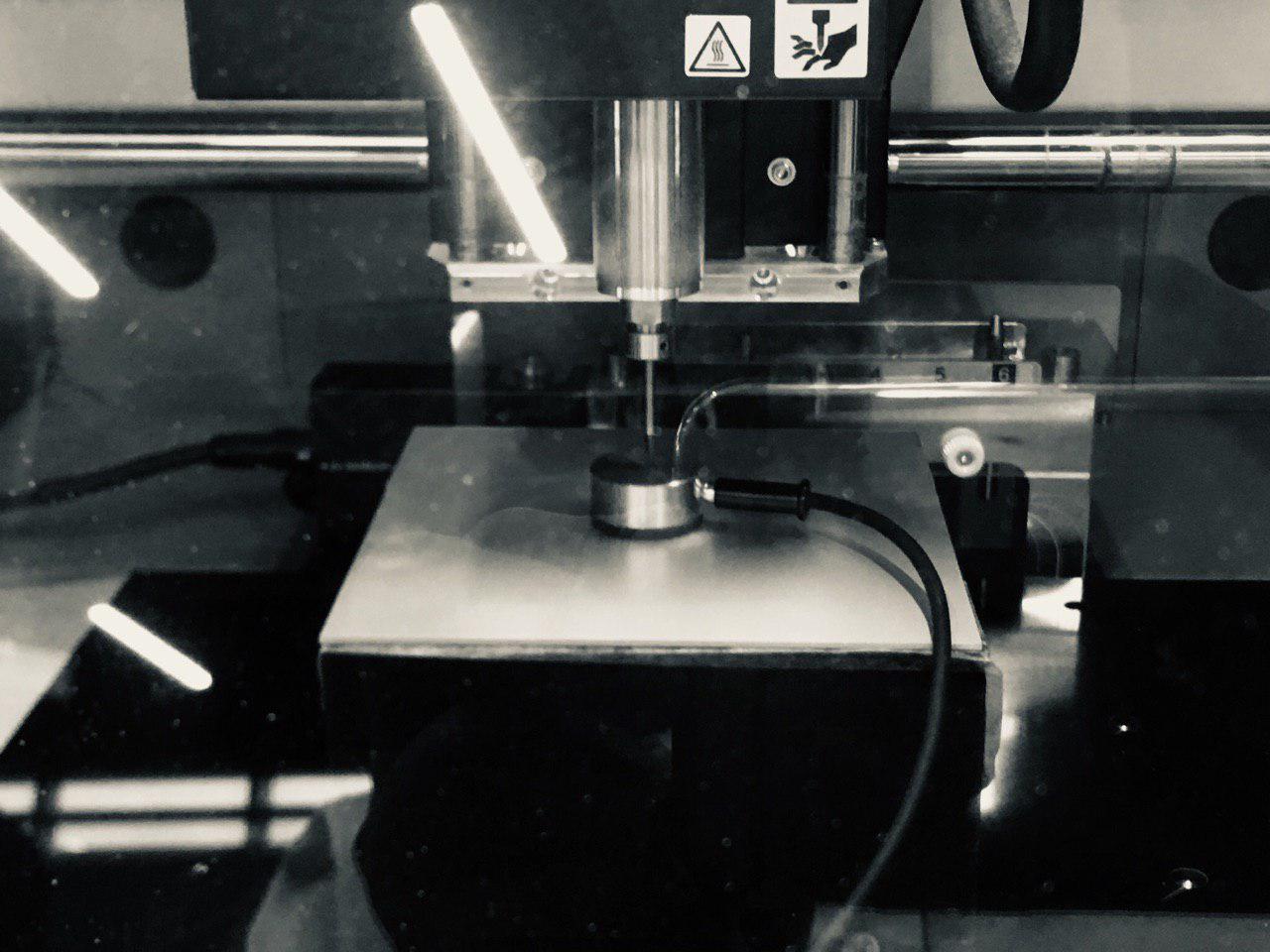
Prepared my board using milling technique.
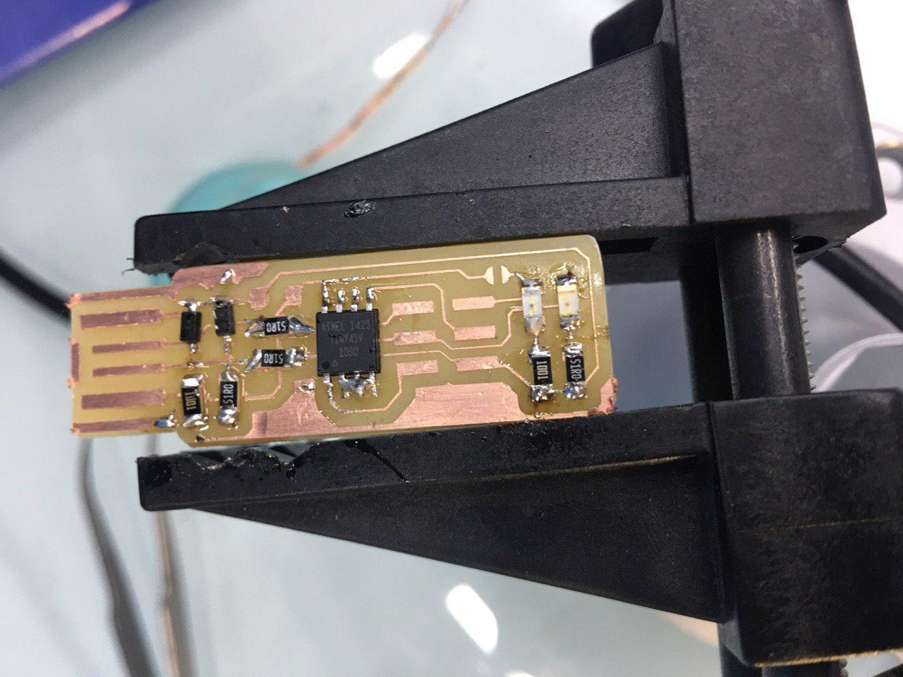
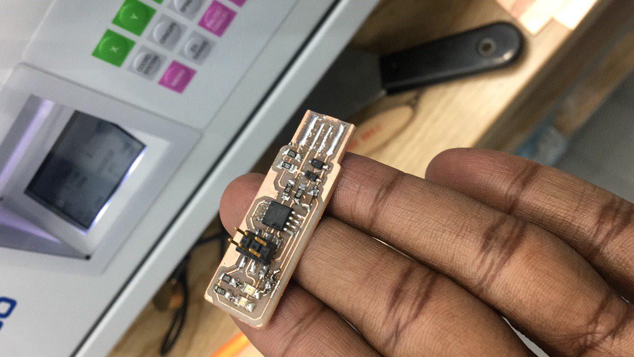
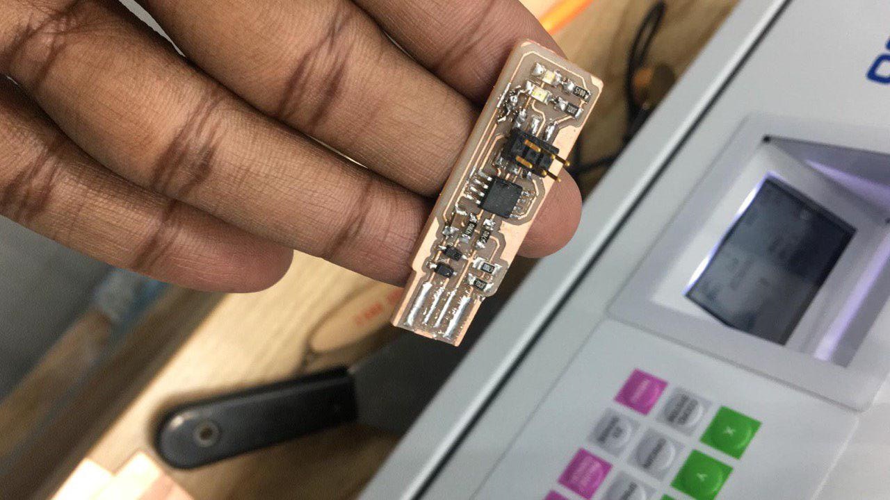
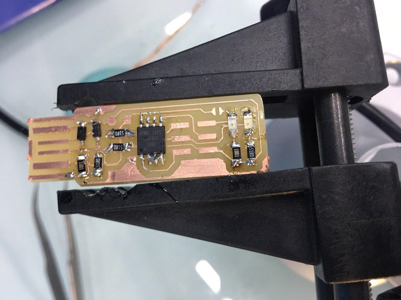
List the components and do soldering
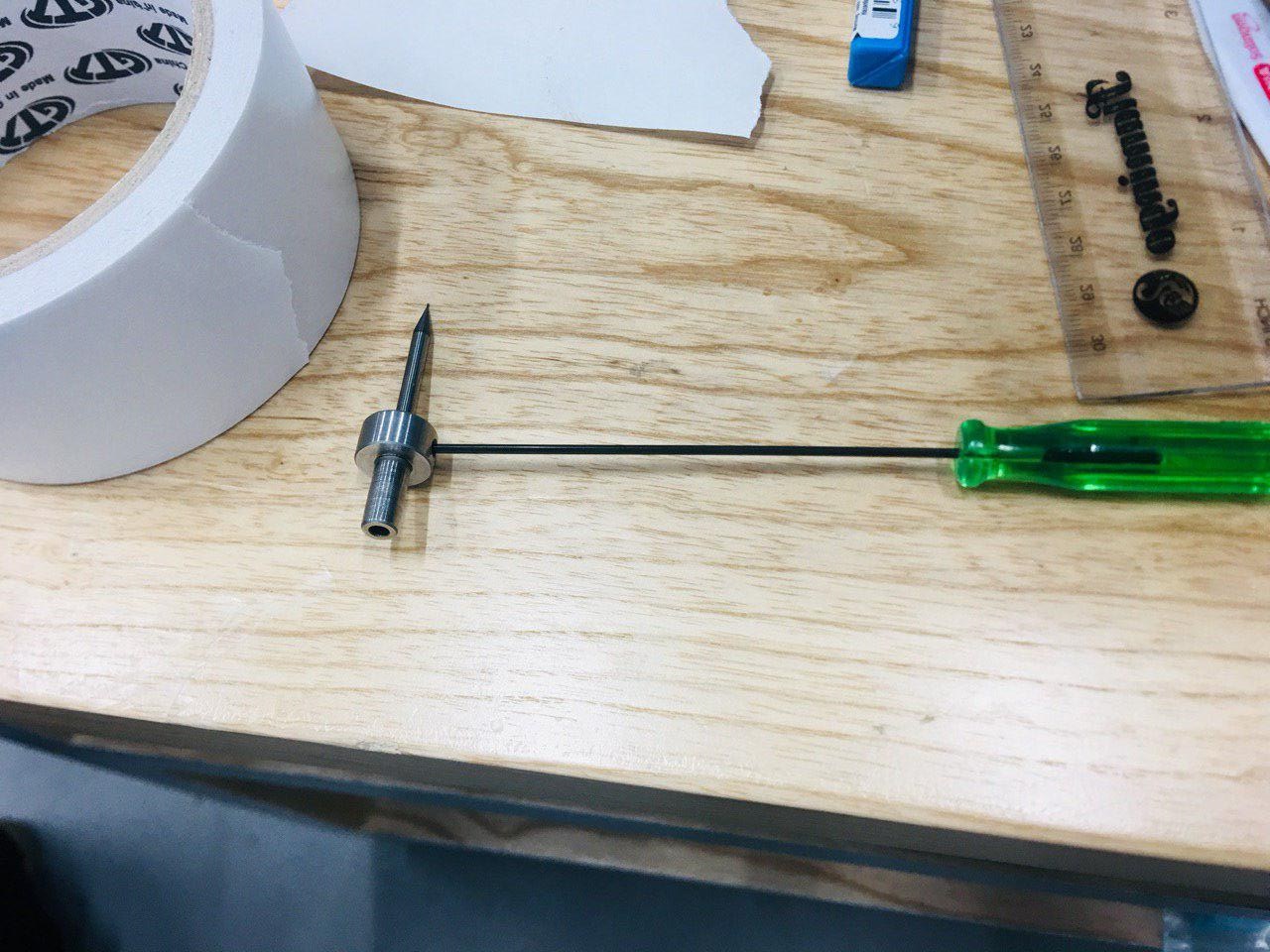
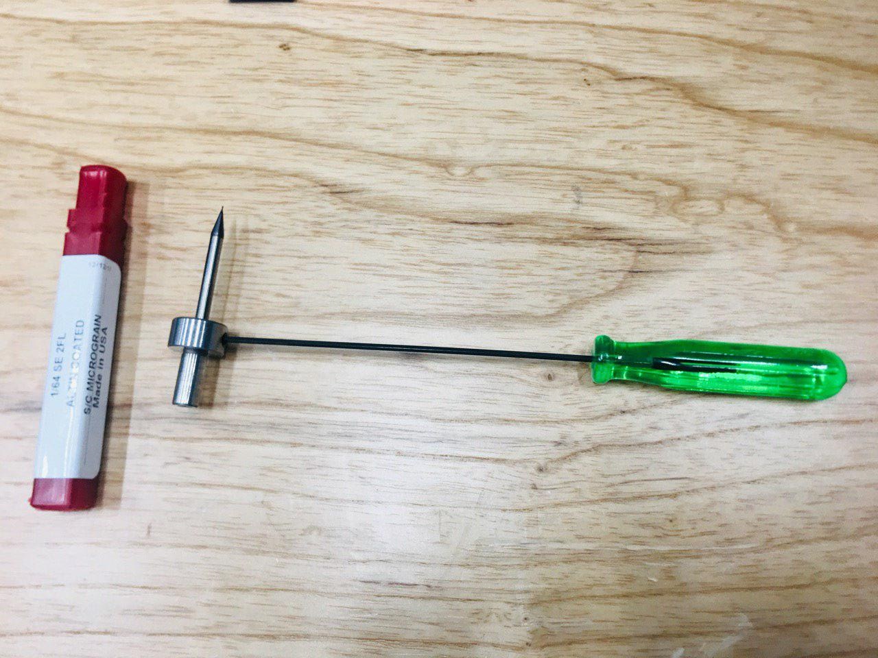
The parameters we will use are:
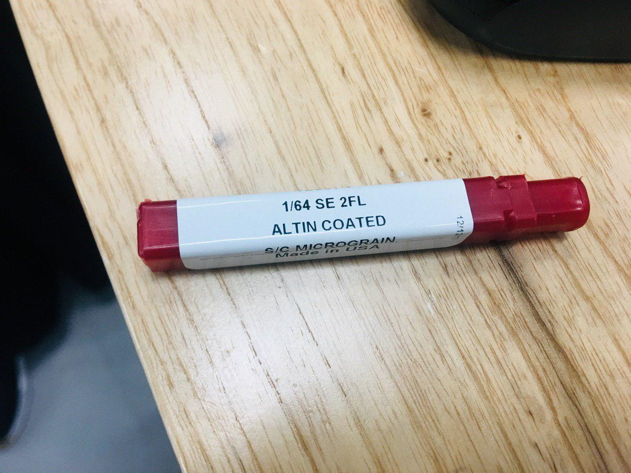
Tool diameter 1/64 for tracing, 1/32 for cutting (around 0.4mm and 0.8mm respectively)
Cut depth for tracing 0.5 and for cutting 0.8 (with max depth 2.8)
Offset number for tracing 3 and for cutting 1
Offset stepover 0.5
Assignment of the week:
Make an in-circuit programmer by milling the PCB, then optionally trying other processes.
To handle this assignment,we refered to the following tutorials provided by Fab Foundation:
1. Building the FabTinyISP
2. FabISP Production and programming
3. Arduino as an ISP
4. PCB Milling with Roland MDX-50
5. Making flexible PCBs with a Vinyl Cutter
6. Fab ISP Models compilation
TESTING THE BOARD CONNECTIVITY
Before connecting the board to the computer, it's very important to check the connectivity of the components. I used the multimeter and the schematic image as reference and everything was correct.
PROGRAMMING MY ISP PCB Board
To Program the ISP I followed each step of this tutorial.
I used AVR programmer. First, I connected the programmer to the 6-pin programming header on the FabISP board and got GREEN LIGHT! It means that the header is soldered correctly and the board is getting power.
Steps to program the ISP:
Download FabISP Firmware
Compile the Firmware
Make hex
Set the fuses so the board will use the external clock (crystal)
Program the board to be an ISP
Check if FabISP device has been successfully programmed and is recognized by the computer.
Remove the 0.0 OHMS Resistors once the board is programmed. Ready!!
Group Assignment:
we tried to mill our first board and this absoulyly was very rich learning opportunity , we made many mistake and we will try to avoid them in the future
.png)