Week 15. Networking and communications
24.04.19 Class
During this class we have explained all the communication systems between cable systems, such as the BUS line of RS-232, RS-422 and RS 482, as well as communication through I2C, which is what I will use in my final project , SPI, CAN and USB communication.
We have also seen models of communication without wires, all the communication languages they use, the bits of each communication, etc.
Week planification
This assignment I decided to leave for the end, after delivering the final project, since I have decided to start working from now on, I do not have much time to do everything I want to develop for the final project and if I leave for later I will not arrive to be able to deliver it on time and do a decent job to deliver on June 12.
Individual assignment
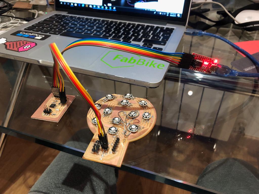
For this assignment I decided to join and communicate via bus line my phototransistor with my neopixel LED array, for that in the input assignment I had to repeat the phototransistor board since in the first one I had not included in it the pins to join it through bus line with another board, this pins are for RX, TX, GND and VCC. Visit my input and output assignments to see the boards that I use to do this assignment.
 The communication via BUS I do a sketch connecting the phototransistor and the neopixel led array, in order to turned on the array with diferents colors depending on the data measured by the phototransistor. I programmed in Arduino two sketches (one for the array, and one for the phototransistor) using the Software Serial Library. I used Serial_sw.write() to save the readings from the phototransistor board and serial_sw.available() to recieve the data from the sensor board in the array board. On the other way I used serial_sw.read() to read the data in the array board and used it to control its lights.
I have had problems from the beginning, because when I connect my two boards between them and connect them to the computer, the magic was done, what I had been waiting for all the fabacademy, the neopixel array board started to smoke, it burned.
As I have not had time to react to make a new board, I decided to directly connect the neopixel led to an arduino and communicate this with the board that has survived the phototransistor.
With the connection of the board made, I have uploaded the two different programs and it has started to work as shown in the video.
For the final project I have also used communication between two types of sensors, this time with a different communication, this has been through I2C that allows connecting several sensors through two cables exclusively.
Below you can see in the final project process the development made in the programming and communication part in this sense.
My files
Neopixel array comunication program
Phototransistor communication program
Conclusions
It has been a busy week for the trip but I think that throughout the fabacademy we are going to learn a lot about programming and I am looking forward to using sensors. After many weeks and being very busy, I was able to finish the assignment and also advance in my final project.
