Week 04. Computer-controlled cutting
06.02.19 Class
On February 6, Neil explained us all the details about cutting techniques using a knife cutter and a laser cutter. It has given us a lot of knowledge about the adjustments of the materials and the joints that we make to join them together. He tells us that we have to create bases and tests with different measures to get the perfect fit so that it does not have slack or that it is not too compressed.
He has made a lot of emphasis on this subject of adjustments since it is a very important part when manufacturing to avoid using adhesives or other methods of union.
In addition, he has encouraged us to test the machines for different purposes, such as using the vinyl cutter to cut printed circuits on copper tape and thus get adhesive circuits. He has also invited us to try, apart from the normal adhesive vinyl, the textile vinyl for textile customization. This textile vinyl I have used often and as a goal I have proposed to try the simple adhesive vinyl and create a circuit with adhesive vinyl copper.
With the laser cutting machine he explained that everything that can be cut is usually in two dimensions, but it has encouraged us to try cut patterns that give you play in the fabrications as hinges and folding or as patterns that can give dimensions in 3d These last ones I have never tried them and I have decided that I am going to launch a test on cardboard to see the result that is achieved
Week planification
Like every week at the beginning I have decided to organize the week to realize the objectives I want to fulfill. I show them in the following Excel sheet.
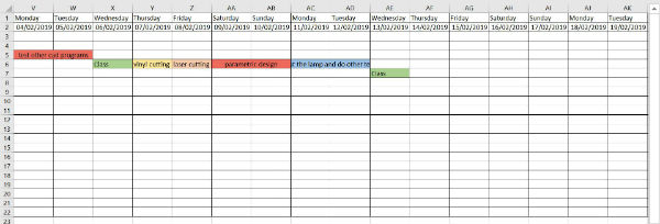
For Thursday I have proposed to carry out the tests of cut with simple vinyl to leave adjusted the machine and to realize the first test.
On Friday I will use the laser cutter to adjust the 3.5mm cardboard material with which I will perform this assignment, I will also do cutting and engraving tests, fitting tests between different pieces and I will try patterns that give me three-dimensional surfaces.
Saturday and Sunday I will develop the parametric design on a lamp that I already have created and manufactured in MDF. I will also prepare the cut files to cut it on Monday in the fablab.
On Monday I will cut the lamp and prepare a circuit to take it to the vinyl cut and between Monday and Tuesday I will develop this last test.
If I have more time, I will continue working on the new website, which is gradually taking shape.
Group assignment
I am a remote student and then I have no colleagues in my own fablab who do the fabacademy. So I’ve done it on my own and what I’ve done in this part has been to describe and characterize the machines that I’m going to work with this week. I do not put workflows or working methods, since throughout the assignment I am explaining them while developing the different jobs that I have proposed. The machines that I will use are:
Roland GS-24
Max cut area: 58.4x2500 cm.
Max cut depth: 1.2 mm.
Dimensions: 86x32x23.5 cm.
Weight: 13.5 kg.
Max cutting force: 350 gf.
Silhouette Cameo 2
Max cut area: 30x300 cm.
Max cut depth: 0.8 mm.
Dimensions: 53x12x16 cm.
Weight: 2.95 kg.
Max cutting force: 210 gf.
Trotec Speedy 100R
Laser type: CO2
Work dimensions: 61x30.5 cm.
Piece max. height: 17 cm.
Laser power: 12-60 watts.
Laser cut and engraving
Once the tools of my fablab have been characterized, I start using my laser cutting machine by designing a small cut and engraving test to adjust the parameters of this for the corrugated cardboard of a layer of 3,5 mm. that I am going to use.
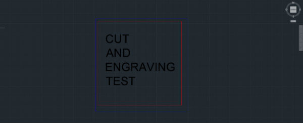
I have used the autocad program to do the work since it is the program I use normally. In the image you can see the types of line used for each action, red and thickness 0.00 for cut, blue and thickness 0.00 for selection box and black and thickness> 0.15 for engraving.
If we want to make other cuts we will put other different colors and we will modify them in the job control program that is the one that pilots the machine. This order of different cuts is made many times in the textile world to cut first the inner part of the patterns and then the outer part.
Once we have made the design:
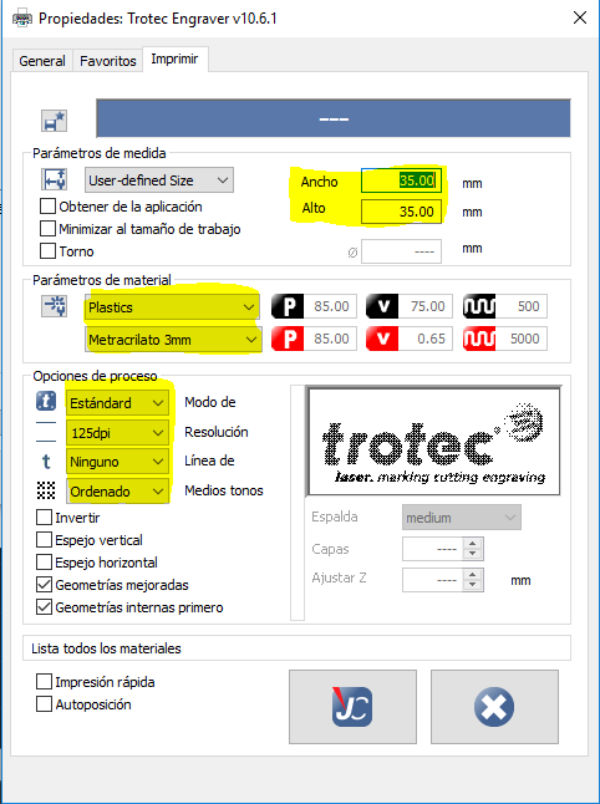
press> file> print> printer> trotec engraver v10.6.1
Properties> custom properties> (job control)> width: width of the blue selection square, height: height of the blue selection square, material parameters: type and specification and type of engraving process> JC
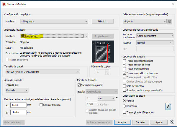
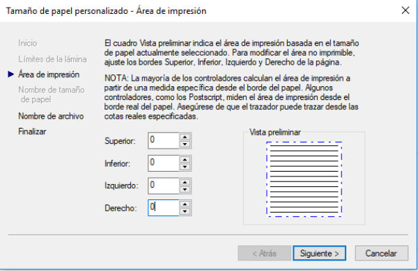
Modify standard paper sizes> user defined paper> modify> remove the margins> next> put the name of the file we want> next> end> accept
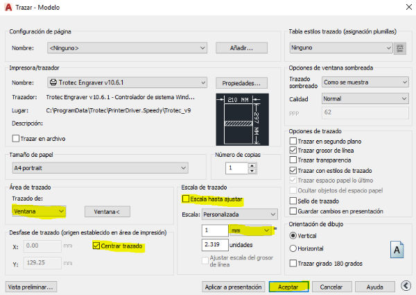
Create a temporary file> accept Layout of:> window> we select the blue square of selection Center plot No scale until adjusted mm TO ACCEPT
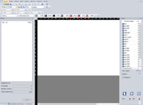
Now we open the Job Control program that is the controller of the Trotec Speedy 100R laser cutting machine.
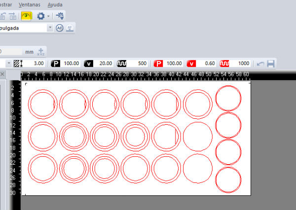
We drag our work from jobs to the cutting table. We give the eye to see our design. This should appear with the cut lines in red, the engraved parts in black and so on with those we want to make in our work.
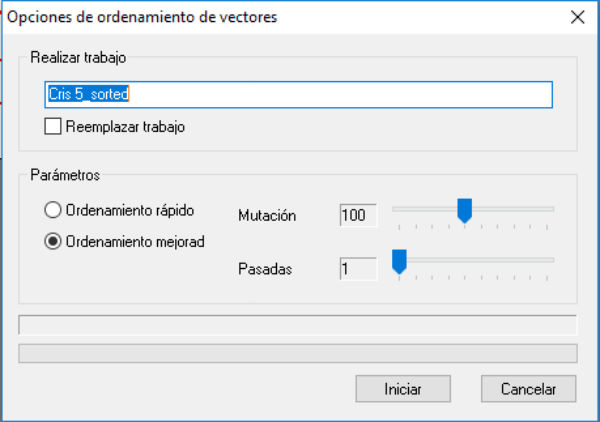
Press right button on our work> selection of vectors> replace work> start (this serves so that the machine optimizes the routes that it realizes when working).
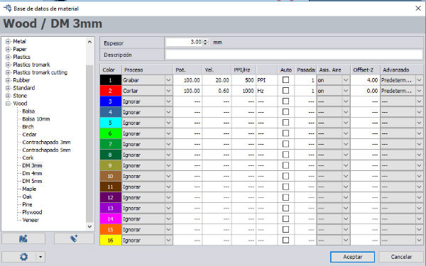
If we press the right button outside of our design, on the workbench> configuration parameters, we can see the parameters of the actions, in power, speed, passes, offset. And we can also see the order of the actions and the action assigned to each color.
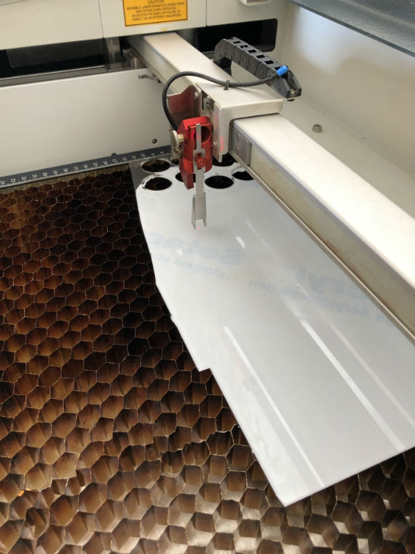
Once this is done we only have to focus the machine on the material with the gauge we have on the machine and give the play to start cutting.
Once launched different samples of cutting and engraving and known the optimal parameters for our type of machine and the cardboard of 3.5mm that are the following:
Engraving: power = 80% / speed = 10/PPI.HZ=500/Offset=1.00
Cut: power = 100% / speed = 2.6 / PPI.HZ = 5000 / Offset = 000
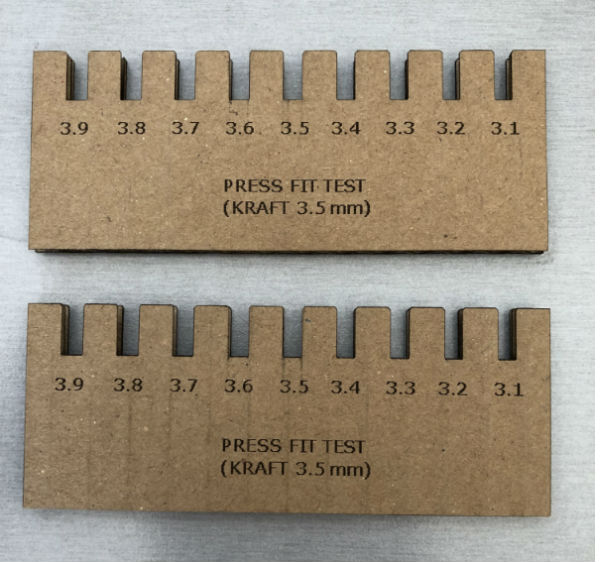
I have created a pressfit test to know which is the best fit for my material in the joints. As the cardboard is 3.5 mm. I have made a joint scale of 3.1 to 3.9 mm. To perform adjustment tests. From this test I conclude that the best pressfit for my cardboard joints is the 3.6mm measure.
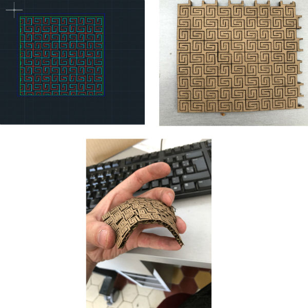
In addition to this press fit test I wanted to create a three-dimensional surface with the cardboard using the following pattern.
To finish, make clear the basic safety standard when using this machine:
DO NOT FORGET THAT THE MACHINE HAS TO BE CONSTANTLY MONITORED WHILE WORKING.
Vinyl cutting
For this work I have decided to use my favorite design program that is the adobe illustrator, but to cut the sticker that I am going to make for the laptop, I will use the two cutters that we have in our Fablab, the silhouette cameo 2 and the Roland GS 24. In addition, I will explain the two work flows that I use for each machine once I have the design done.

I’m going to make a simple design with which to cover the luminous apple of my mac. The design that I have thought has been an X inside a circle like the deadpool logo.
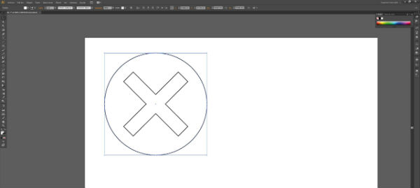
To make the cut with the Roland GS 24 we will do it from the illustrator directly and to do it with the silhouette cameo 2 we will need to export this file in extension .dxf.
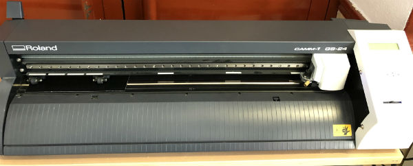
Workflow Roland GS 24: The first cut will be made with the Roland GS 24, for this we need to put the vinyl in the machine and place it with respect to the head. To do this we turn on the machine, lift the rollers, introduce the vinyl getting the rollers to be inside the vinyl and this same inside the white marks of the machine and lower the rollers again. We press:
Select sheet> roll and the machine will focus with the vinyl.
Within Illustrator we must place the work table of the file at the origin x: 0 y: 0 and this is located in the lower left corner of the worksheet. Once the design is located in the corresponding area on the sheet, we can go to:
File> print> printer> Roland GS 24 We also select the support size> defined by controller and then in placement we select the lower left corner to match with the origin of the work table that we have selected before.
Select settings> continue> printer selection> Roland GS 24. Printing preferences> getting from the machine> accept. And the work to be done begins.
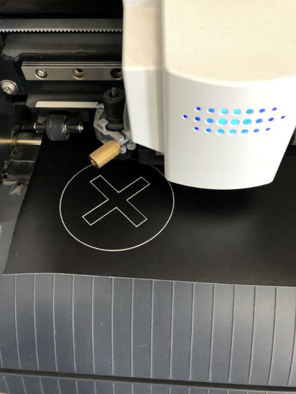
And we would have the vinyl cut and ready to transfer. Since I do not have a transfer paper, I use my trick, which is to place a masking tape on the vinyl that I want to transfer, since it has little adhesive, and with this tape I transfer the vinyl to the surface where I am going to stick the vinyl.
I advise that the surface where the vinyl is going to be placed is clean with water or glass cleaner and very dry. Once the vinyl is glued, before removing the bodybuilder’s tape, I also recommend pressing it with a special spatula or with a card such as the Madrid subway.
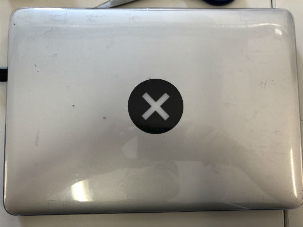
Workflow Silhouette Cameo 2: In this case, to introduce the vinyl, we must loosen the roller from the right side, center the vinyl with the machine ruler on the left side, close the roller again and give the option on the screen to load medium. Then the machine itself will take the vinyl and introduce it into it.
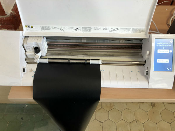
Once the design has been made and exported in .dxf, we have to open it with the special silhouette studio program. Special program that is used to perform work with this machine. To start:
File> open …> select the file
To configure the size of the support that we introduce, in page configuration> size:
Custom> width: x> height: y.
Once configured the page size and the file placed in its place. We select the send window in the upper margin.
In this, the file is already shown in gray, what you do not want to cut, what if you want to cut it in red and what you want to cut the outline in bold red. In addition, it shows us a drop-down in which we must choose the material, the action we want to perform and the tool we are using in the machine.
Once we select the material, the cut and the tool, just below it shows us the position of the blade that we must put in the head, the cutting speed and cutting pressure that will be used and the passes to be made.
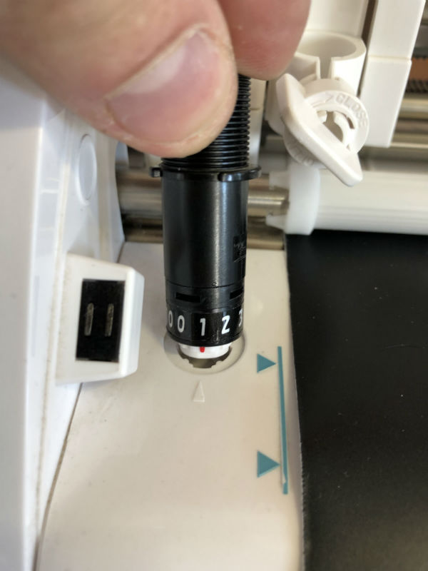
To change the position of the blade, we must loosen the handle that holds it in the head, extract it upwards and in the part of the machine where the hole is, position it in the red point and turn it to the number that appears in the program . Then we must put it back in its place and close the handle.
With the vinyl cut we would have made the sticker and apply it as I explained in the workflow of the Roland GS 24.
The parameters used for this vinyl in the Silhouette Cameo 2 have been the following:
Blade type: serrated blade
Blade position = 1 / Speed = 5 / Pressure = 10 / Passes = 1
Parametric design
For this part of the assignment I have decided to parameterize a lamp that I had designed for laser cutting. The next photo shows the lamp that I am going to redesign and parameterize.
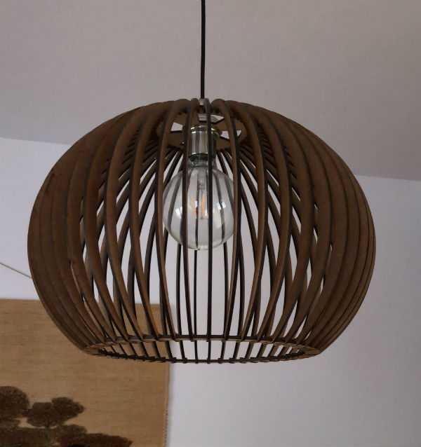
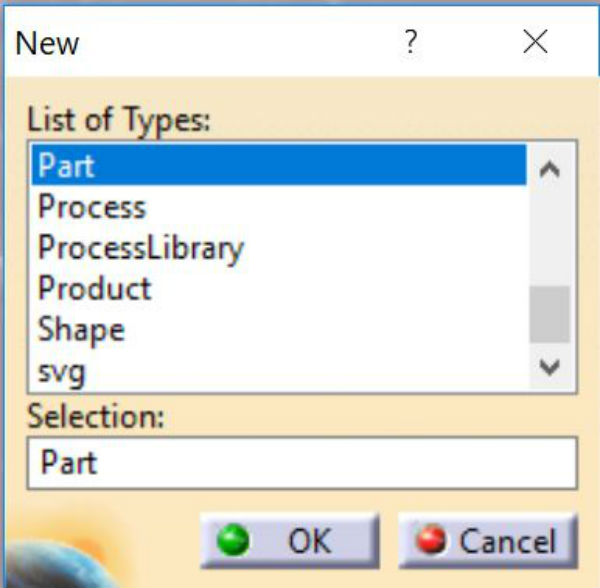
The program that I am going to use for the design and the parameterization is going to be catia. To start with the design I open a new file type Part.
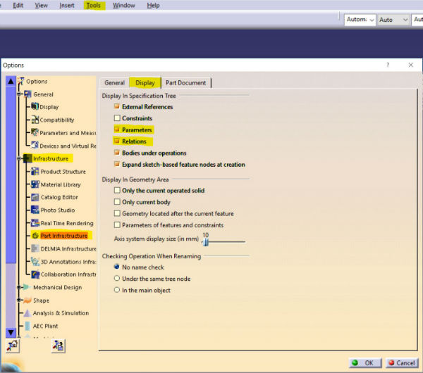
And before starting to design:
Tools> options> infrastructure> part infrastructure> display> activate parameters and relations.
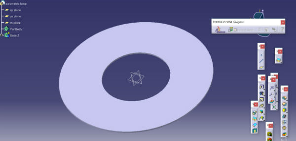
After this I will think what measures of my design I will parameterize and what measures I will leave related to others. I’m going to start with the top of the lamp. It consists of an inner diameter (which depends on the bulb that you want to place), an outside diameter and the openings for the ribs that make up the lamp.
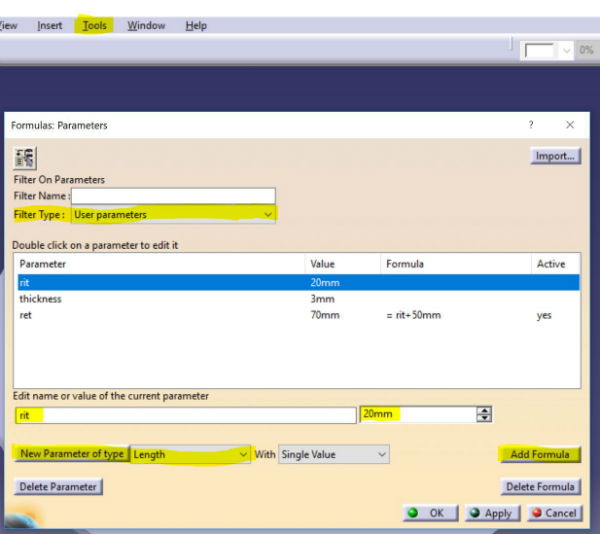
Once the design is created, I proceed to create the measurements that will be parameterized:
Tools> formula> filter type> user parameters> new parameter of type> length
and I create the three parameters for the three measurements that I have: inner diameter, outer diameter and thickness. The outer diameter I want to relate to the interior therefore on the outside: add formula = rit + 50mm. You have to put the units because otherwise the program does not understand the values well.
In the operations tree, a subfolder called parameters has been created. When I open it, I can find the parameters created. I name them with their characteristics and I give them a base value. It must be borne in mind that diameters can not be parameterized in catia, only radios can be parameterized. From this tree is where we will change the values so that we can change the whole design.
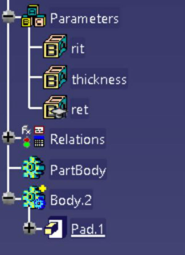
Once we have created our parameters, we have to apply them to the measurements of our design. For this we open the part where the measurements are placed and on this data:
Press the right button> edit formula> we select in the tree the parameter that we want to assign, we verify that next to the measurement a square appears as a parameter has been assigned and we give it to ok.
In this way, the parameter to measure would already be assigned. We perform the same with the internal radio and the external radio of the design.
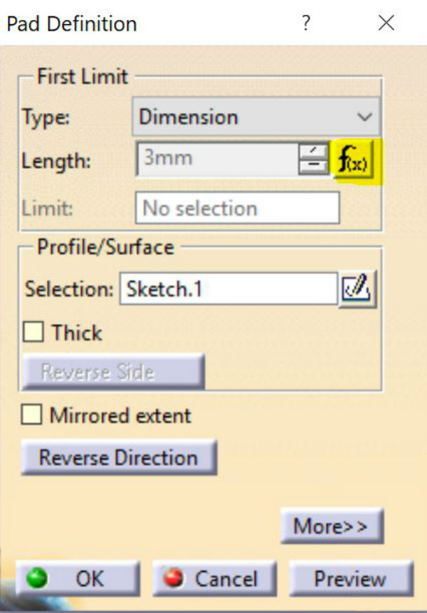
Once we have this, we can continue creating as many parameters as we want and continue with the design until we get the final product.
To make this screen recording I used an open source free program called OBS studio. After the design process, I go to the manufacturing process, for that I have to save the files in 2D drawings and save them in dxf. For this, catia has a planimetry module:
Start> mechanical design> drafting.
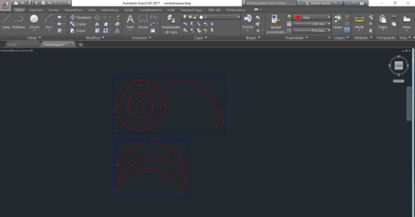
These planes I export in dxf. and I have them ready to modify them in autocad to send them to the laser cutting machine with the workflow explained previously.
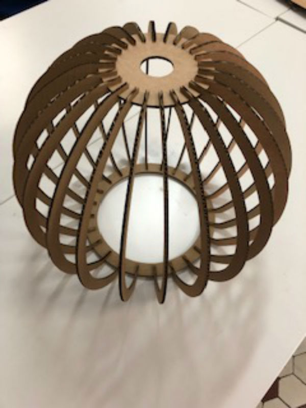
Once cut, we have the following result:
My files
Parametric lamp CATPart
Parametric lamp SVG
Conclusions
This week has been easier since the computer controlled cutting is one of the jobs I do most in my fablab and what I wanted to show in this assignment are all the workflows that we have and leave a little written all our work methodology. This week has been easier since the computer controlled cutting is one of the jobs I do most in my fablab and what I wanted to show in this assignment are all the workflows that we have and leave a little written all our work methodology.
