
Week 08. 3D Controlled computer machining
07.03.19 Class
The first thing that must be clear for the assignment this week is that you have to do something big. Neil has shown us different machines that we can find in the market if our fablab does not have a cnc. In my fablab arrives on Thursday 08, so it arrives perfect for the assignment.
After showing us the machines he also gave us a masterful on the materials that we can use like MDF or plywood, depending on the orientation of his fibers he behaves in different ways.
In addition, he explained the most important part of this assignment that are the tools used with this cnc milling machine.
Drill bit: ends in a point and is used to cut vertically (drilling).
Router bit: they have different shapes and cut horizontally (they mill).
End mil: depending on which is it can cut both horizontally and vertically (drilling and milling).
The tools have different characteristics: number of lips, diameter, number of spirals, length of cut.
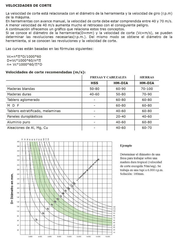
Another very important part for this assignment is the feed rate of the machine, the speed of the spindle and the depth that we give to cut the end mill. I will explain this part in the group assignment, explaining the formulas we use to calculate them.
The different fixing methods are also important, in my case the machine fixes the pieces by vacuum. It also explains the importance of slaughter tables, in our case we have a 10 mm mdf sacrificial layer.
On the other hand it also explains how to make the milling in 3 dimensions, once I get used to the milling in 2 dimensions I will start to try the milling in 3 dimensions, for now it is a lot of information that I have to assimilate to be a new machine for me.
Week planification
During this week I will try to do the complete assignment and also perform the part of the individual assignment of last week. For this I organize the week as follows:
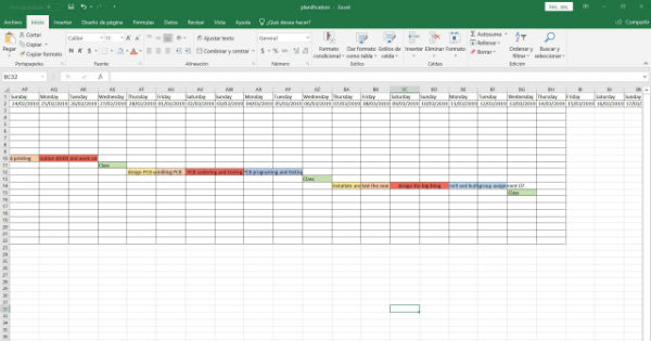
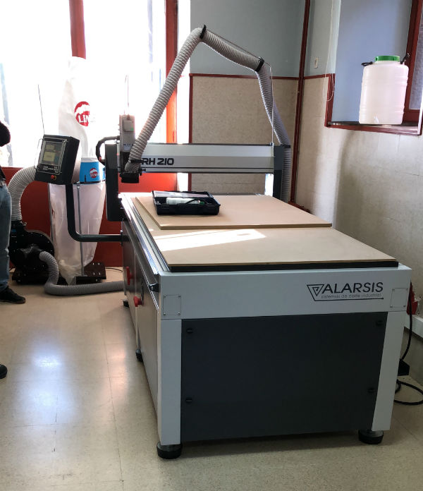
On Thursday they bring the machine, the Alarsis FR210, of dimensions 2000x1000x120. During this day we will have to install the machine, assemble it and put it into operation. Also, the staff of the factory will give us a basic course of its use.
On Friday we will do the first tests to prove that everything works and that it does not have any problem. Also, throughout the day I will design what I want to mill and build.
On Saturday and Sunday I will use it to design the model and leave everything ready for Monday to manufacture and assemble it.
On Monday I will make it and I will assemble it and in the afternoon I will start uploading all the documentation to the website.
On Tuesday I will keep it for the part of the group assignment of the previous week, since I have not had time to do it.
Group assignment
It is the novelty of the fablab as it arrives one day after the class of this assignment. The machine is brand alarsis, model FR210 with working dimensions of 2000x1000x120 mm. It does not have automatic interchangeable heads but you have to change them manually. But it has the possibility of installing a cooling system of the tool by means of a drill for when working with metals.
The adhesion of the materials is by vacuum pump and has an incredible power of absorption for this purpose.
For the use of this machine it is necessary to take safety standards as it is a relatively dangerous machine and it is advisable to use gloves, glasses and plugs when working with it.
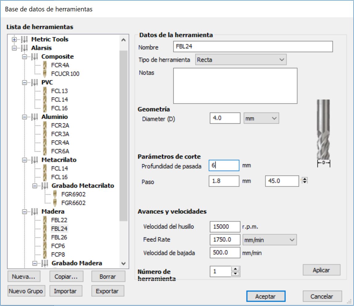
Next, I will explain how we calculate in our fablab the speeds depending on the size of the tool, the number of lips etc etc.
Once we know the speeds that we are going to use depending on the selected tool, in our case the 4mm flat bur. I will explain the workflow that is used to send the files to the machine.
We started by creating a design in autocad or in another vector program of 2D design in this case.
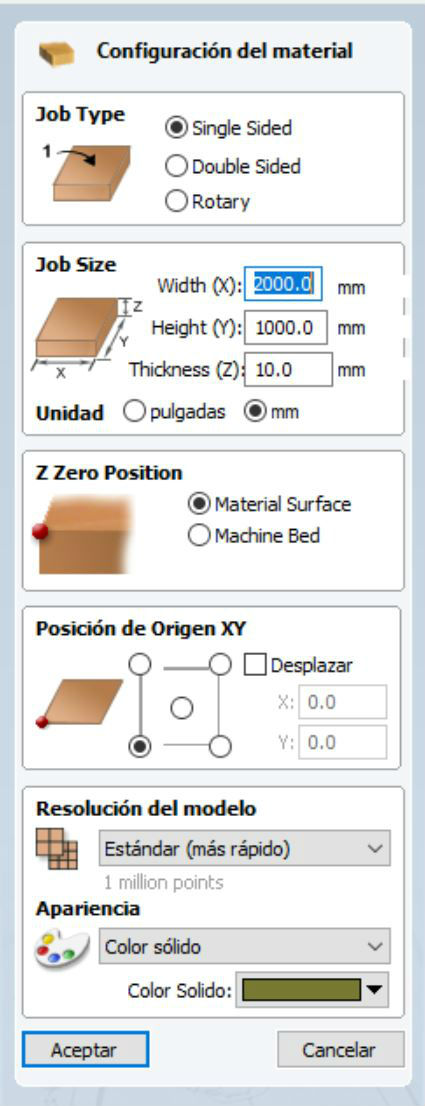
Then we export it in extension .dxf and open it with the program: VCarve Pro 9.5. This program has a profile saved with our machine that has been supplied by the manufacturer, as well as a library with the tools that the manufacturer has also supplied to us.
The first thing we do in this program is to indicate the dimensions of the work table that we are going to use and the thickness of the material that we are going to use and we accept it.
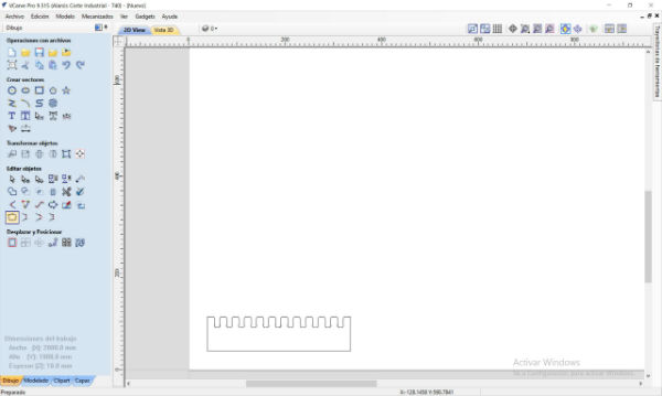
Now we import the model that we have saved in vector file and we check that it enters our work table.
After this we open on the right side the toolpaths tab and it will show us the different types of functions we can perform on our work. Emptying, recessing, drilling etc.
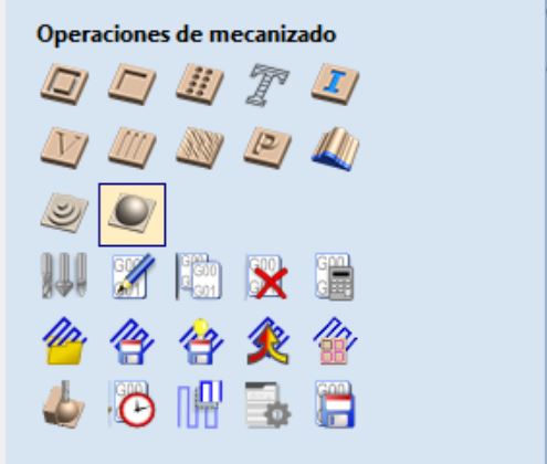
We select each action that we are going to carry out and within each one of them, we select the initial and final depth, the type of tool, the compensation of the tool and the input of the same towards the material.
For the depths, always the initial is 0, since we have made the 0 in z on the surface of the material and the final depending on the action we are going to perform. For cutting it is always advisable to give a couple of decimas more to ensure the cut.
The type of tool, in our case like the machine is new, we are using the tools supplied by the manufacturer and in its library we already have all the characteristics and recommended speeds for each one. If we had different ones we would have to add new tools to the library, giving it all its characteristics and its speeds.
The compensation of the tool already depends on how you have made the design and how you want to make the same in each action.
The entry of the tool into the material is always recommended to go on ramp to avoid damaging it, even if it is horizontal and vertical cut.
Once we have selected the above, we select the vector on which we want this action to be carried out and we give it to calculate.
In this way we will generate a new action in the action tree. We must repeat this step for each action that we want to perform (cutting, slotting, drilling, engraving) and in this way create different actions to be performed. You have to take into account the order of them as it was taken into account for laser cutting. The total cut will always be done at the end.
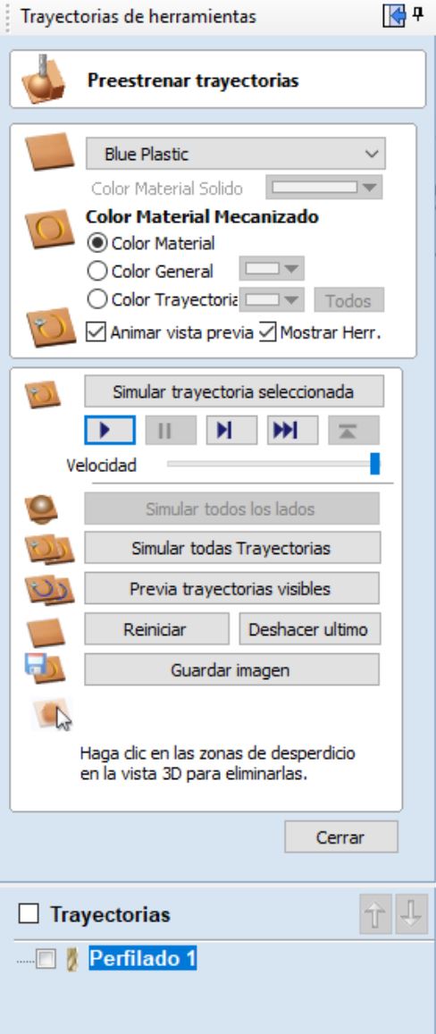
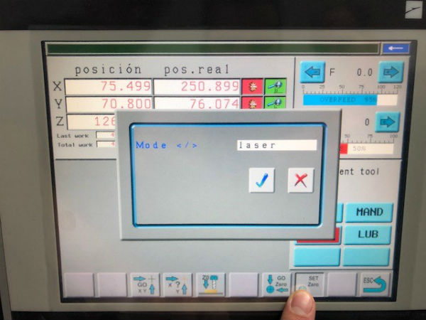
Once we have generated the actions,we select the postprocessor, in this case: CeNeCe_TEX_MTC(mm)(.iso) for this machine and then we keep them in a pendrive as g-code and we go to the machine to launch the works.
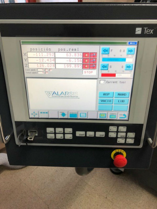
The first thing we do is turn on the machine and give it twice to the emergency mushroom to start working.
We place the sacrificial layer in its place and on it the material that we are going to work with, in our case 10 mm MDF. Once both materials are located, we connect the vacuum. The pump is so powerful that it takes the material to work through the material of the sacrificial layer.
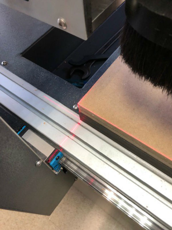
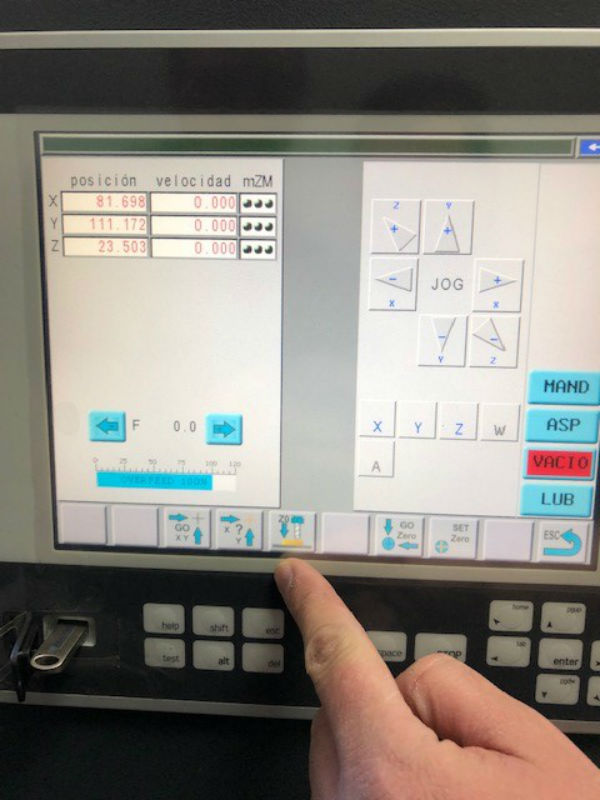
To do the zero in xy, we connect the laser of the machine and we approach it to the corner of our material, once placed we press on the machine to make the 0.
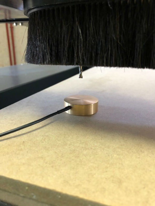
To make the 0 in z we need to place the probe on our material (with the vacuum connected, since it makes the material lower) to connect it to the machine, bring the head to it, and once it is next, press 0z and slowly lower the tool until touching the probe and the zero will be made.
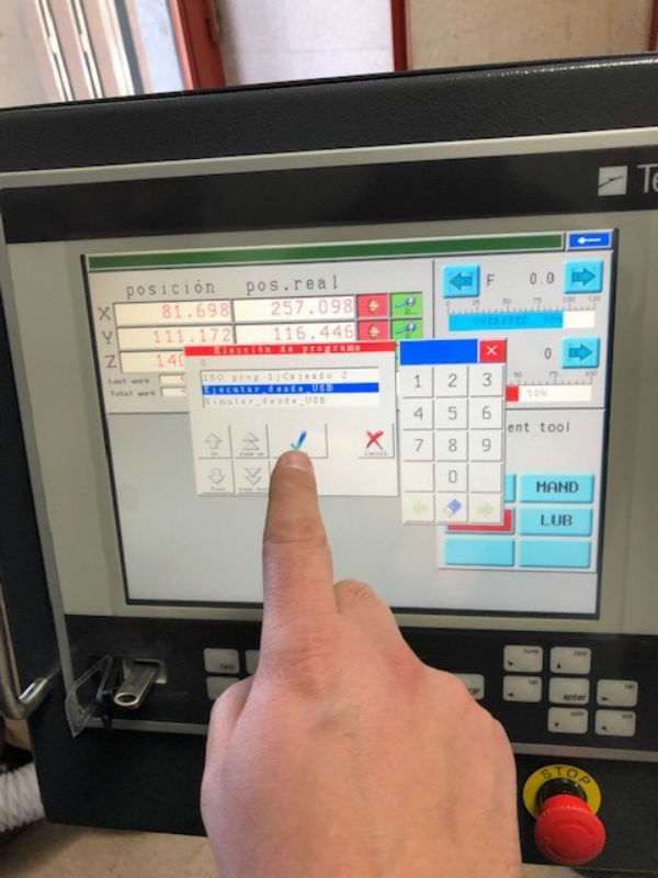
With these steps we already have the machine ready to launch our work. We connect the aspiration to absorb the excess and we go to the pendrive to find the job. Once we have it, we launch it.
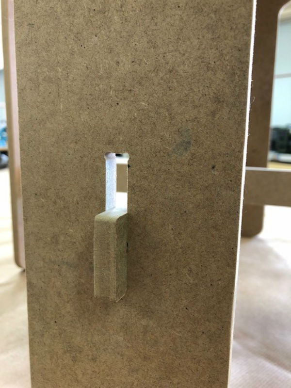
We would already have the work done and the pressfit made for our DM of 10 mm.
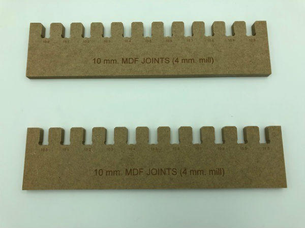
With this we can see the adjustment that has and the quality that a machine with a tool so big.
Individual assignment
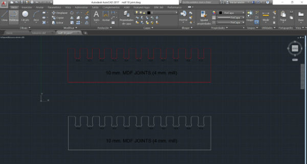
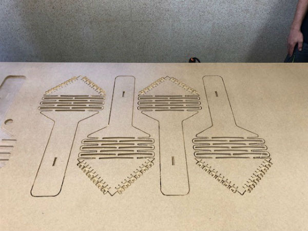
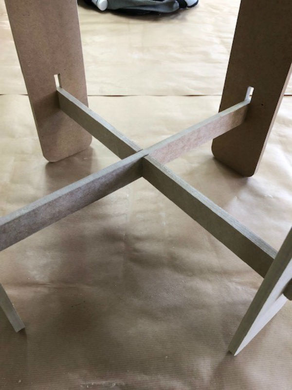
For the individual assignment, the goal is to achieve something big, at least something bigger than what we are doing. I asked my girlfriend what piece of furniture she needed for home, since I have never worked on this machine and did not squeeze it as much as possible at the moment. She has told me that she needs a stool and I have decided to design one that has both joints and flexible parts to experiment with this test.
In the following image you can see the design made.
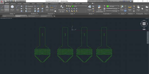
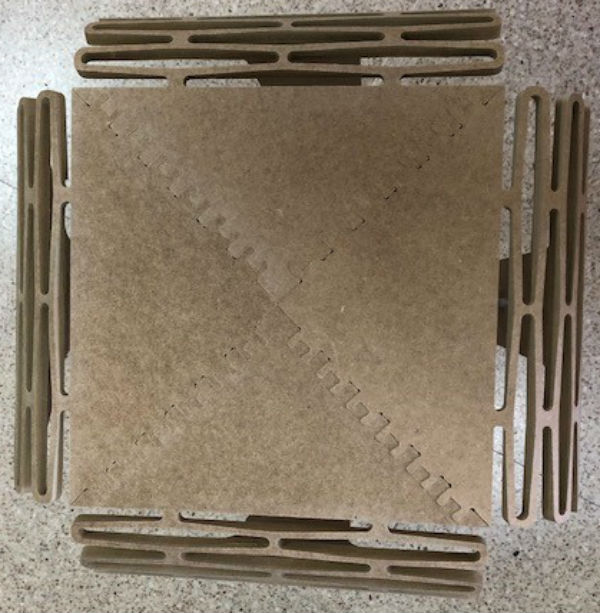
The design consists of 4 parts like the one seen, joined in their diagonals through some joints that you can find.
Then the 4 legs are joined by 2 braces.
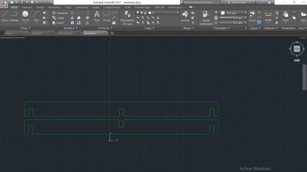
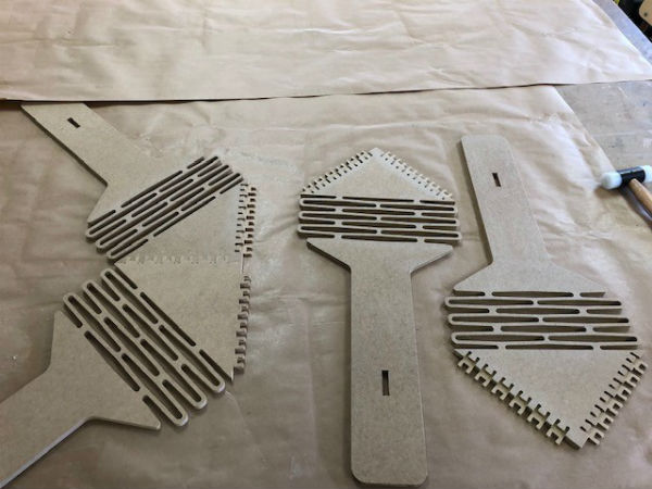
Once we have the design, we pass it to the VCarve processing program. At this point I had a problem, because when generating the milling actions, it does not calculate the trajectories well and gave errors to the vectors. When investigating the program, I have found a series of options to join the vectors that are separated and, with this action, I have recycled the entire design.
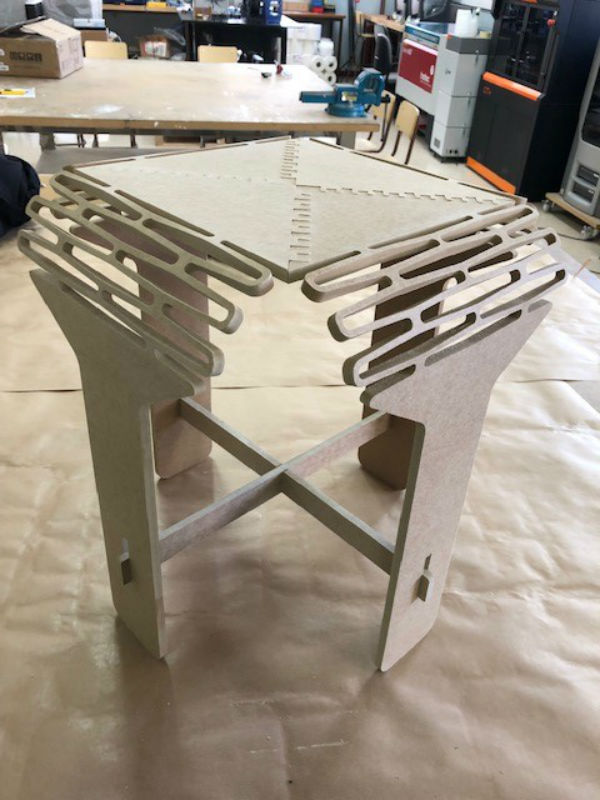
Once recycled and all the calculated actions, I sent the work to the machine as indicated in the group assignment and this is the result:
My files
Conclusions
I loved this new fablab machine and I think it has a lot of potential. This week we had a lot of work in the lab and with the assembly of the new machine we could not work hard, anyway I am very happy with the work done and I think we will do great things in the very near future.